Week 8 - Input Devices
This weeks assignments covered input devices. The individual task was to use a sensor to read something. I decided to use the TLE493DA2B6HTSA1 I2C 3-axis magnetic field sensor to read magnetic fields, as it will be a part of my final project.
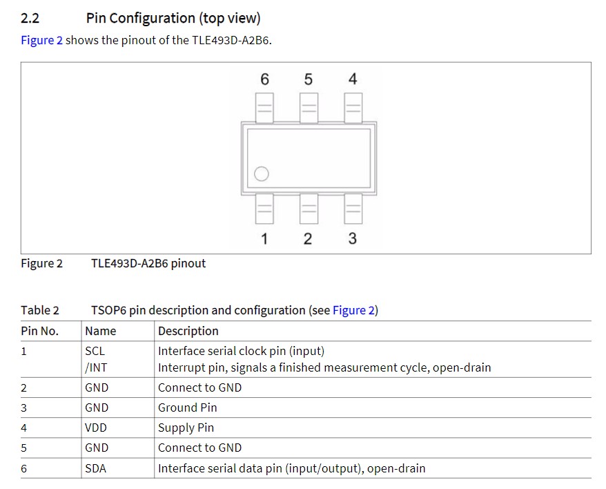
The pin layout of the TLE493DA2B6HTSA1 as provided in its datasheet is shown below. Three of the 6 pins are allocated to GND, pin 4 is VDD at 3.3 V, and the other two pins (SCL and SDA) are meant for I2C communication.
Since most of the sensing/data conversion/communication protocol magic happens within the hall-effect sensor chip, the application setup for the device is relatively simple. Additionally, the datasheet provides the typical application schematic below.
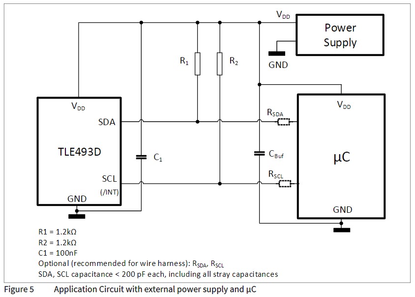
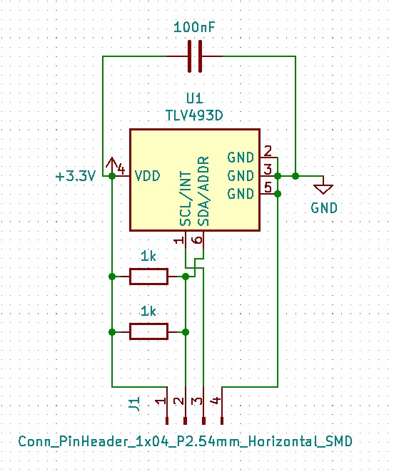
Pullup resistors are necessary for both the SDA and SCL lines. These are connected to 3.3 V with 1kOhm resistor (near the suggestion). Additionally, a 100 nF capacitor is placed at across VDD and GND in order to stablize the voltage at the sensor. A KiCad schematic for the layout is shown below. A 4 pin male header is used to transmit data from a centralized uC.
Black and white pictures of the first iteration PCB layout is shown below for milling on the Roland in EDS (via SVG).


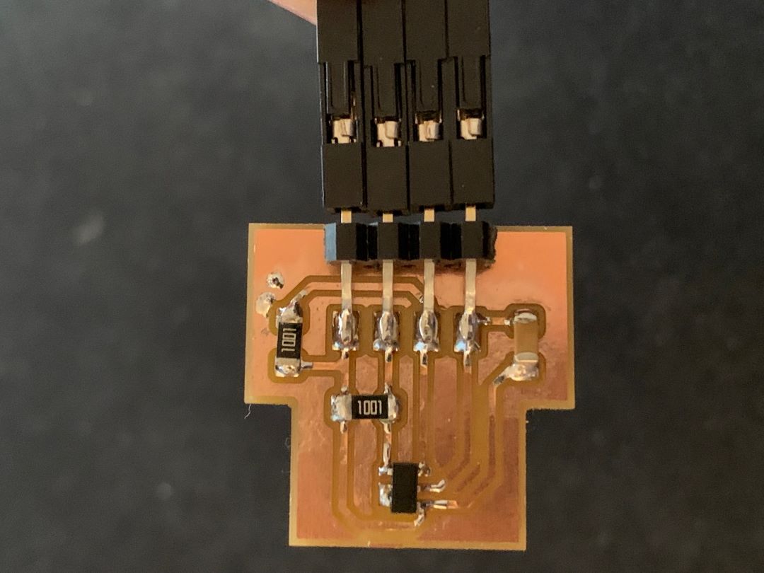
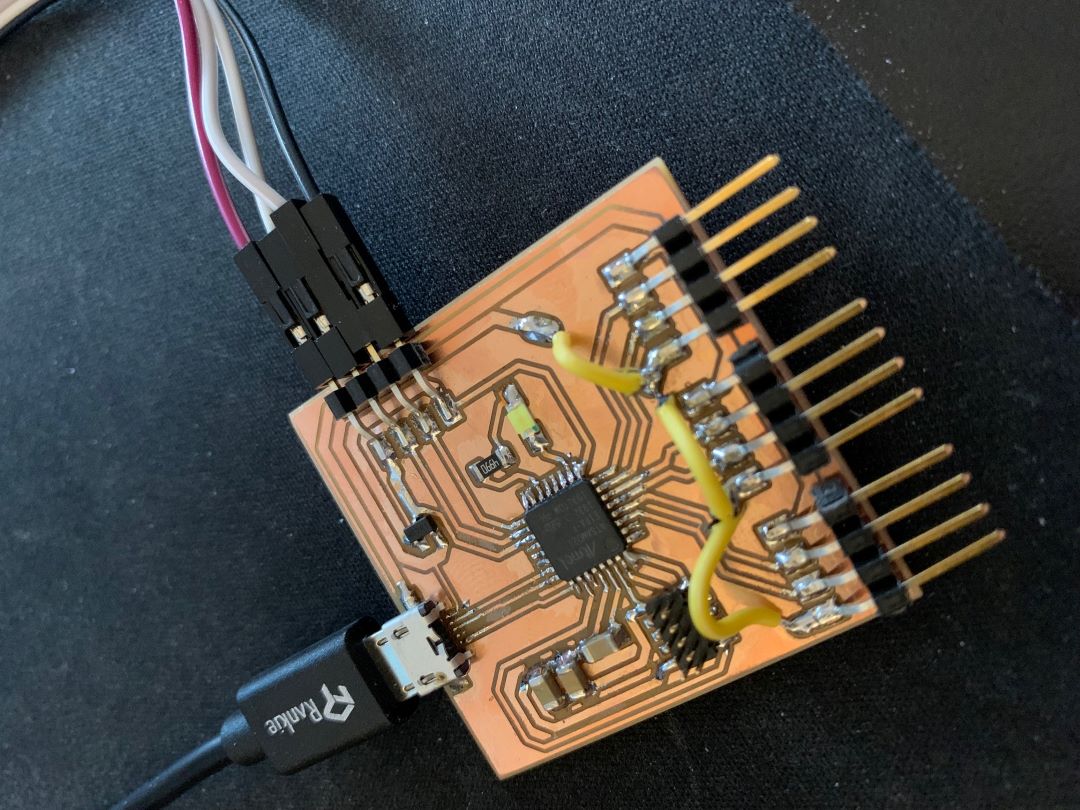
The resulting stuffed board with 4-pin header connected...
I was very reluctant to manually work out the I2C protocol, but luckily Infineon, the maker of the sensor, created and made available on Github a library built for arduino to be used with and communicate with the sensor: TLE493D-3DMagnetic-Sensor. I built off this and tailored it specifically for the A2B6 version that I am using. A snippet of the code I used is below:
#include <Tle493d_a2b6.h>

Tle493d_a2b6 Tle493dMagnetic3DSensor = Tle493d_a2b6(Tle493d::MASTERCONTROLLEDMODE,Tle493d::TLE493D_A0);

void setup() {
  Serial.begin(9600);
  while (!Serial);

  //If using the MS2Go-Kit: Enable following lines to switch on the sensor
  // ***
  // pinMode(LED2, OUTPUT);
  // digitalWrite(LED2, HIGH);
  // delay(50);
  // ***

  Tle493dMagnetic3DSensor.begin();
  Tle493dMagnetic3DSensor.enableTemp();
}

void loop() {

  Tle493dMagnetic3DSensor.updateData();
  Serial.print(Tle493dMagnetic3DSensor.getX());
  Serial.print(" ; ");
  Serial.print(Tle493dMagnetic3DSensor.getY());
  Serial.print(" ; ");
  Serial.println(Tle493dMagnetic3DSensor.getZ());

  delay(500);
}
Unfortunately, the results I got were garbage. The serial monitor just plotted negative -264 for Bx, By, and Bz. After a lot of trouble shooting, I thought of swapping the SDA and SCL pins just in case I happened to swap them in the design by mistake.
That did the trick! I accidently confused the SDA and SCL pins on the SAMD21 centralized uC I was using and had swapped them. Now the problem was that the serial monitor only plotted the x values, the y and z values were unchanging and always zero. After doing some research, I found out that this is a known problem with the A2B6 version...
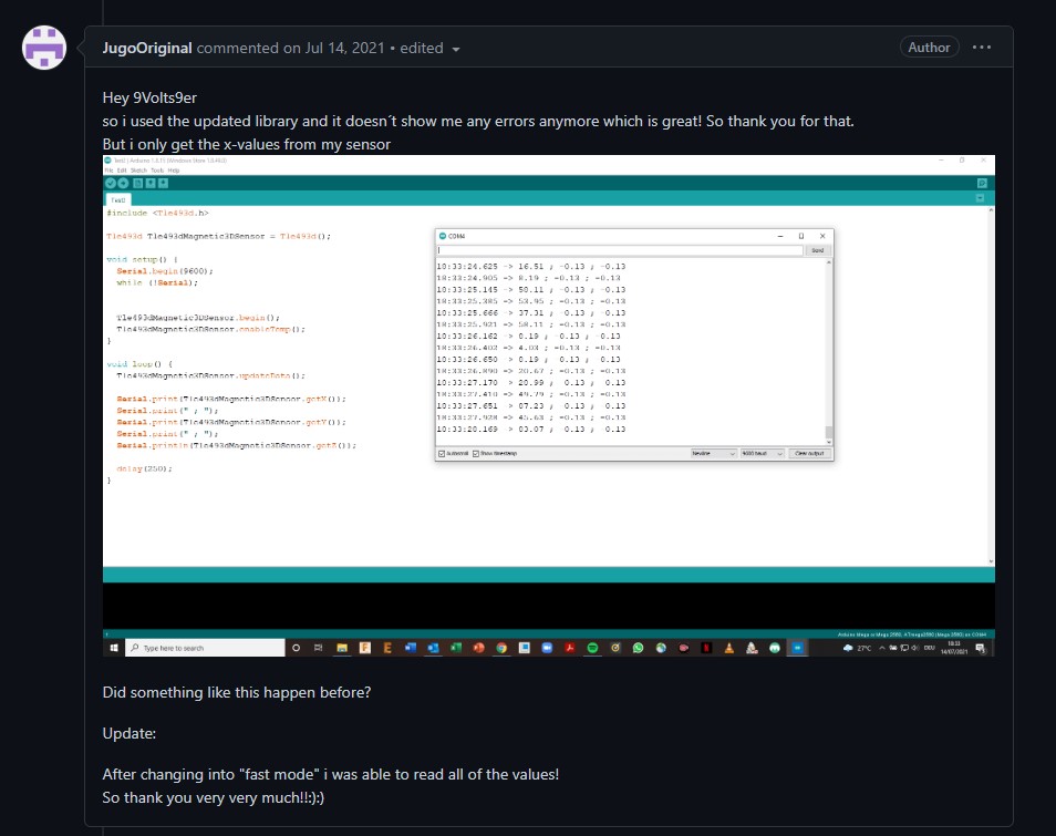
and that the solution is simply to change from MASTERCONTROLLEDMODE to FASTMODE.
#include <Tle493d_a2b6.h>

Tle493d_a2b6 Tle493dMagnetic3DSensor = Tle493d_a2b6(Tle493d::FASTMODE,Tle493d::TLE493D_A0);

void setup() {
  Serial.begin(9600);
  while (!Serial);

  //If using the MS2Go-Kit: Enable following lines to switch on the sensor
  // ***
  // pinMode(LED2, OUTPUT);
  // digitalWrite(LED2, HIGH);
  // delay(50);
  // ***

  Tle493dMagnetic3DSensor.begin();
  Tle493dMagnetic3DSensor.enableTemp();
}

void loop() {

  Tle493dMagnetic3DSensor.updateData();
  Serial.print(Tle493dMagnetic3DSensor.getX());
  Serial.print(" ; ");
  Serial.print(Tle493dMagnetic3DSensor.getY());
  Serial.print(" ; ");
  Serial.println(Tle493dMagnetic3DSensor.getZ());

  delay(500);
}
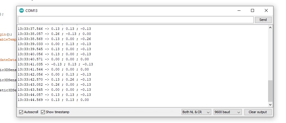
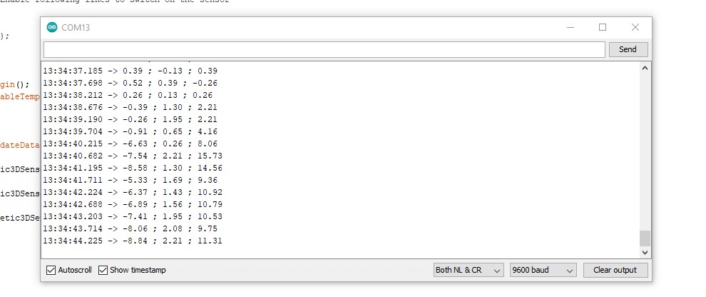
Bingo! Now when I there's no magnet present this is the serial monitor reading I get.
When I place a magnet nearby (see my lousy earbud case magnet below)...
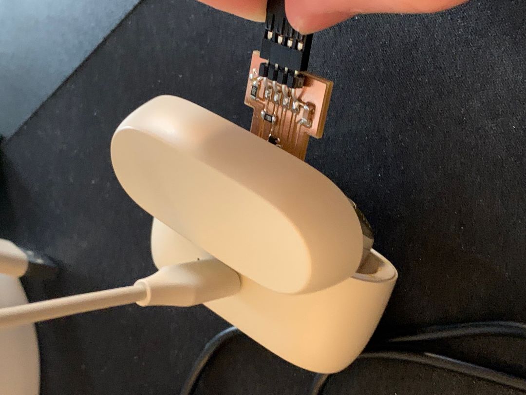
I finally get great readings!!!
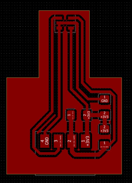
To fix my earlier mistake of swapping the SCL and SDA data lines, I remade the PCB layout for future milling and inclusion in my final project. I also extended the neck and trid to make it as narrow as possible in order to get fine sensor measurements.
Design files for this week can be found here.