Week 9 - Output Devices
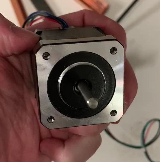
This weeks assignments covered output devices. The individual assignment was to add an output device to a microntroller board I designed. I decided to use a (NEMA17) stepper motor as my output device, as I will need to control three of these for my final project.
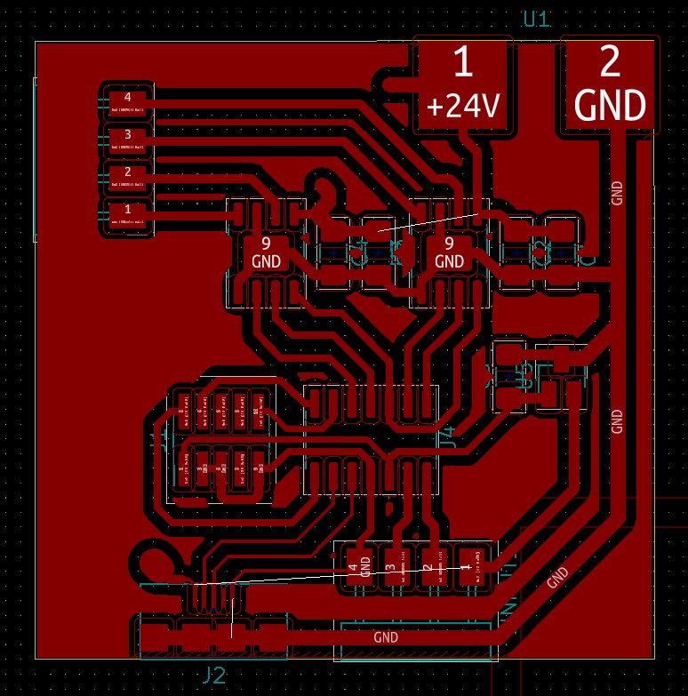
The complexity of working with stepper motors is mostly in the driver. With the chip shortage, integrated stepper driver ICs are hard to come by. Luckily, we still have access to Toshiba TB67H451FNG H-bridges. These are nifty and can be used with a potentiometer and reference voltage to do internal PWM, however, I decided to PWM in software due to the simpler driver board layout and flexibility the approach provides. I used the PCB layout on the website as reference but made some key changes. First of all, the schematic for the board was generated in KiCad.
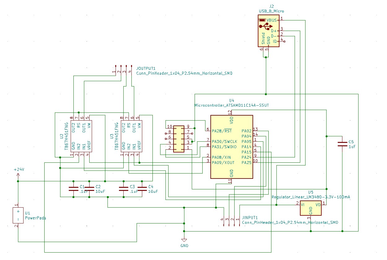
The reference PCB design uses a male USB to power the D11C uC, power the H-bridge/stepper motor, and send data signals for programming. The main change I made here was to disconnect the programming interface from the power interface to provide isolation and prevent me from frying my computer. I did this by replacing the one USB with 3 ports. The first is a micro USB port which is used to power the D11C and program it. This USB connection is then disconnected from my laptop. I used power pads that I can temporarily mount alligator clips from a DC voltage supply and eventually solder this terminal. Then there is a 4 pin header which power the D11C uC during operation and sends signals from a centralized uC board for stepping operations. The ground of the power supply is connected to the ground of the header which assumes that at least one of these are isolated. The black and white PCB layout is shown below to be used on the Roland mill.
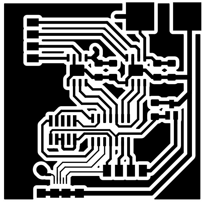
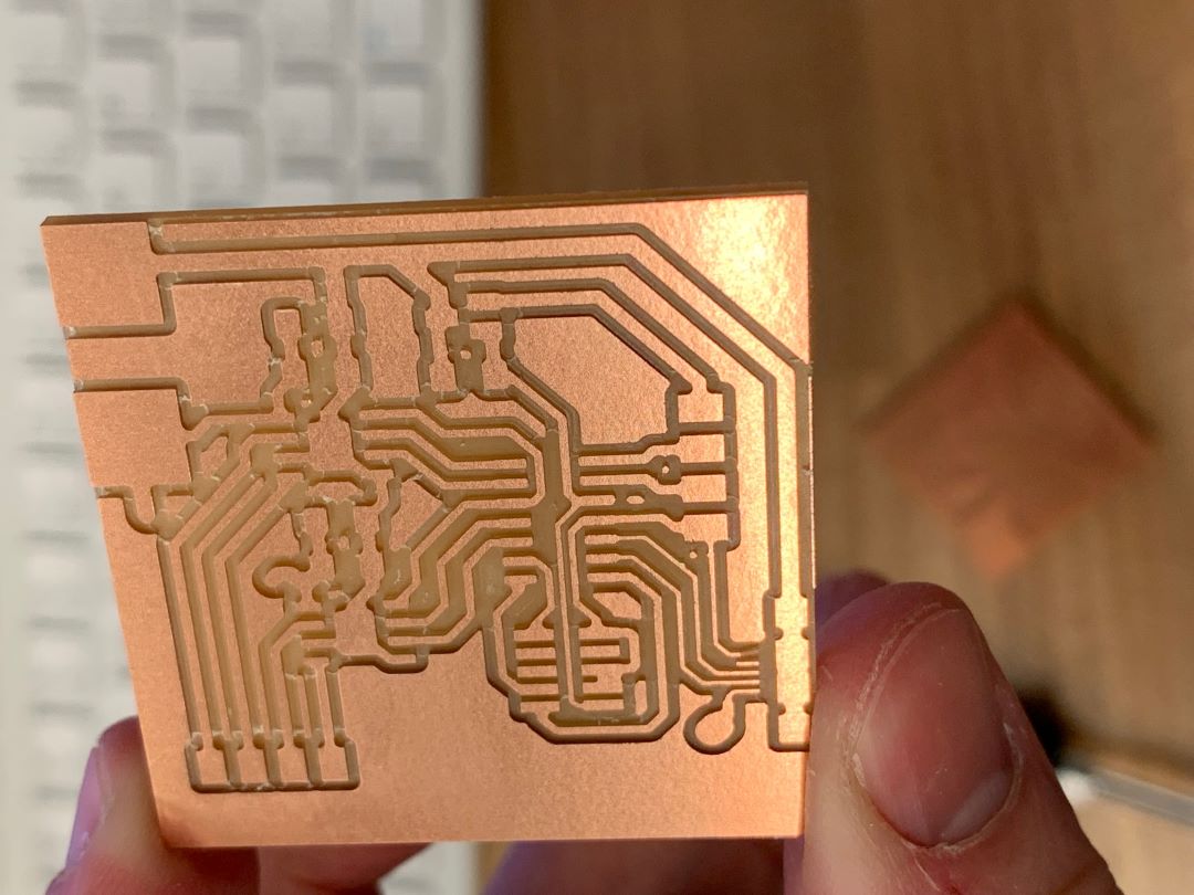
The holes on the edge cut also for through hold soldering. I created pads that are used jumping at two places. The Roland computer was having issues connecting to the Mods server so I decided to use the Othermill. The gerber files were exported from Kicad but I decided that making holes was unnecessary.
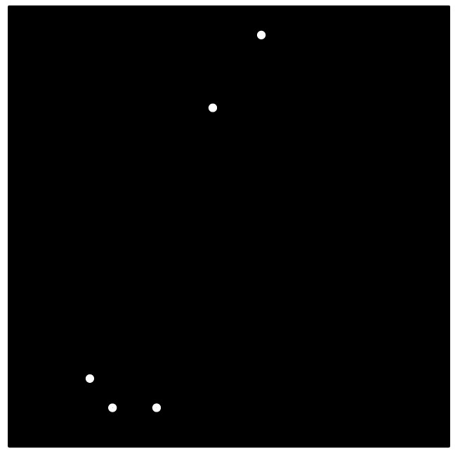
The milled board is shown below.
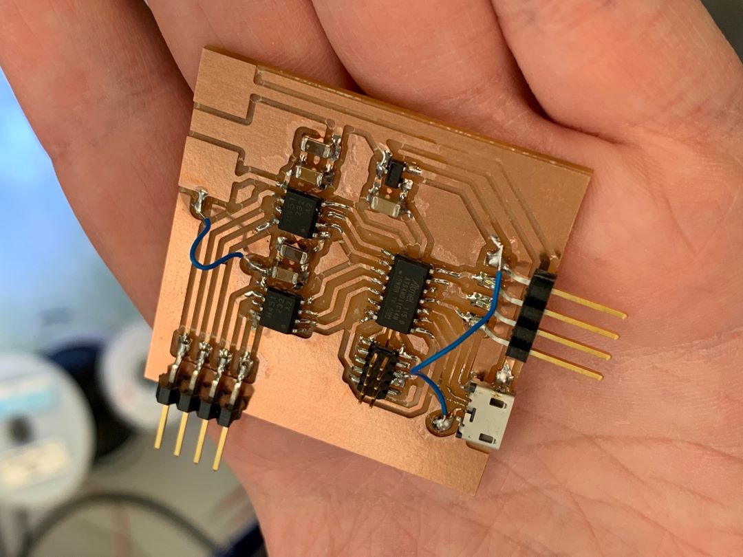
The resulting stuffed board plus jumpers...
To test out the stepper motor and drive operation, I uploaded Neil's code for software PWM to the driver board uC. I then connected a 5V DC power supply to the power pads and tied it back to the VDD pin on the 4 pin-header.
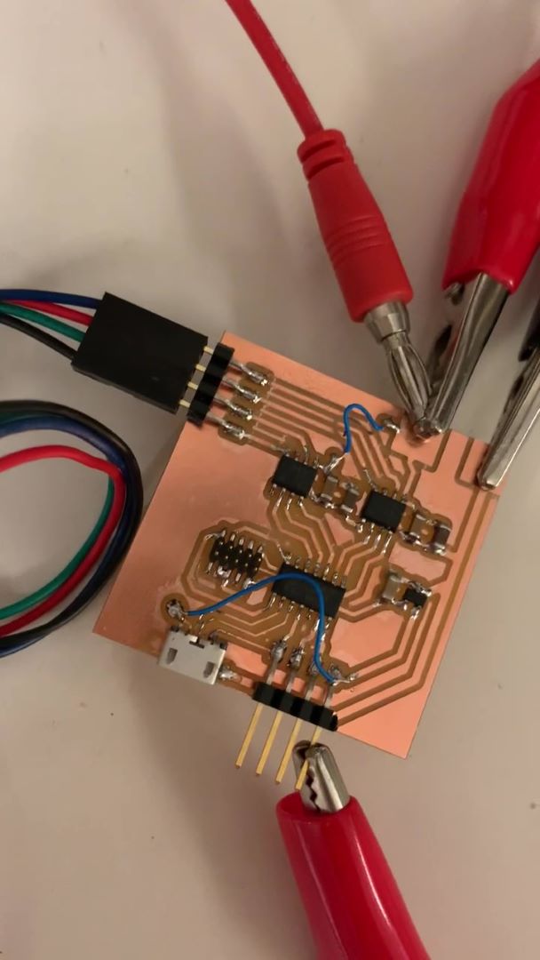
The result was a success!!!
It can be heard in the video and seen at the very end that the half-stepping operation draws more current and creates more vibration than the full stepping operation. This is counter-intuitive to me, as I thought the half-stepping operation was supposed to be smoother, but I did confirm this to be true. Below is a video taken with the only clockwise full stepping in a continuous loop. You can see smooth operation with very little vibration, current, or noise.
Design files for this week can be found here.