This week, I made an in-circuit programmer with a microcontroller. Many appreciations to Yuval for guiding me in the milling process. The steps are as follows:
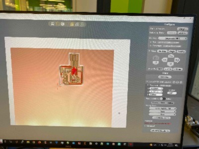
1) Load the circuit design (which Anthony created) onto the software Bantam tools. I After ensuring that the design will be milled onto a empty region of the board, I put in the tool tip (1/64 in flat end) and allowed the machine to calibrate to the height of the milling bed. Then, I was ready to hit start!
2) After a few minutes the milling paused and prompted me to switch to the 1/32in tool tip. I repeated the steps in (1) and resumed the program.
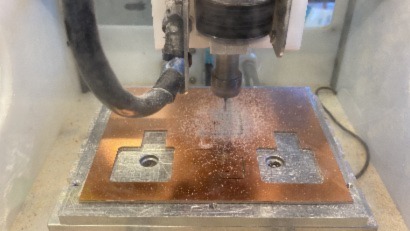
3) I vacuumed off the resin dust, and gently pried out the board.
4) Next, I scrapped off the copper at the tip of the USB connector so the circuit will not be shorted, and moved on to soldering!
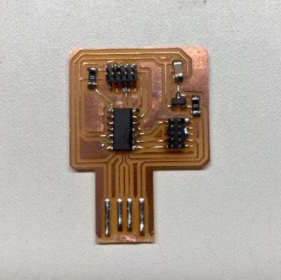
5) The in-circuit programmer consists of a microcontroller, 2 0-Ohm resistors, a capacitor, two external connectors, 1 three way connector, and 1 [insert component]. With a helpful tutorial from Anthony, I learned the Do's and Don'ts of soldering (aka safety practices, solder removal, how to avoid cold-joints, etc.) I careful connected each component to their appropriate locations on the board and removed solder with a solder-wick whenever there was an overflow that would cause shortage. At one point, my microcontroller was a bit misaligned, and Anthony showed me how to fix it with a hot air gun and gentle nudges. Here is finished circuit board!
6) The last step was to program the circuit board and use it to program another device to make sure it works. I had a bit of trouble loading the bootloader on mac so Anthony helped me properly program it.
The group assignments for this week can be found here