This website is for the course How to Make Almost Anything (Fall 2022) You can reach me at
Contact me
alexiaasgari
@gsd.harvard.edu
.
Final Project
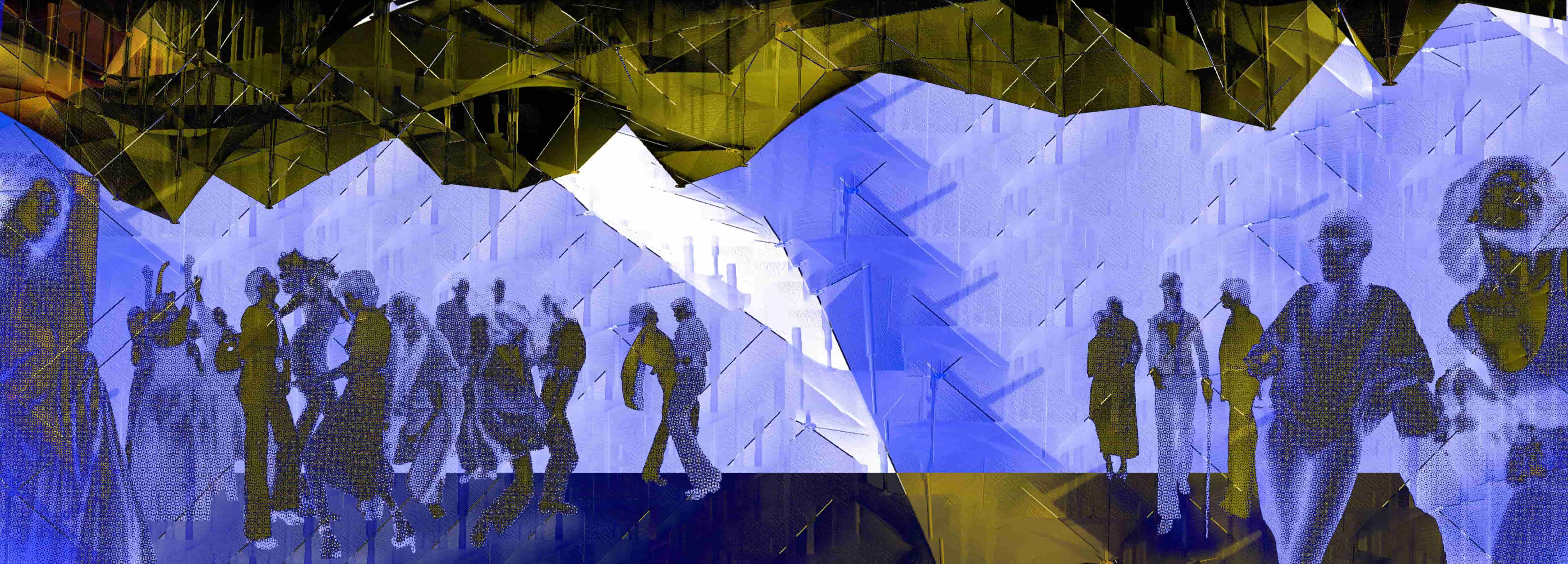
Responsive Installation - Kinetic Ceiling
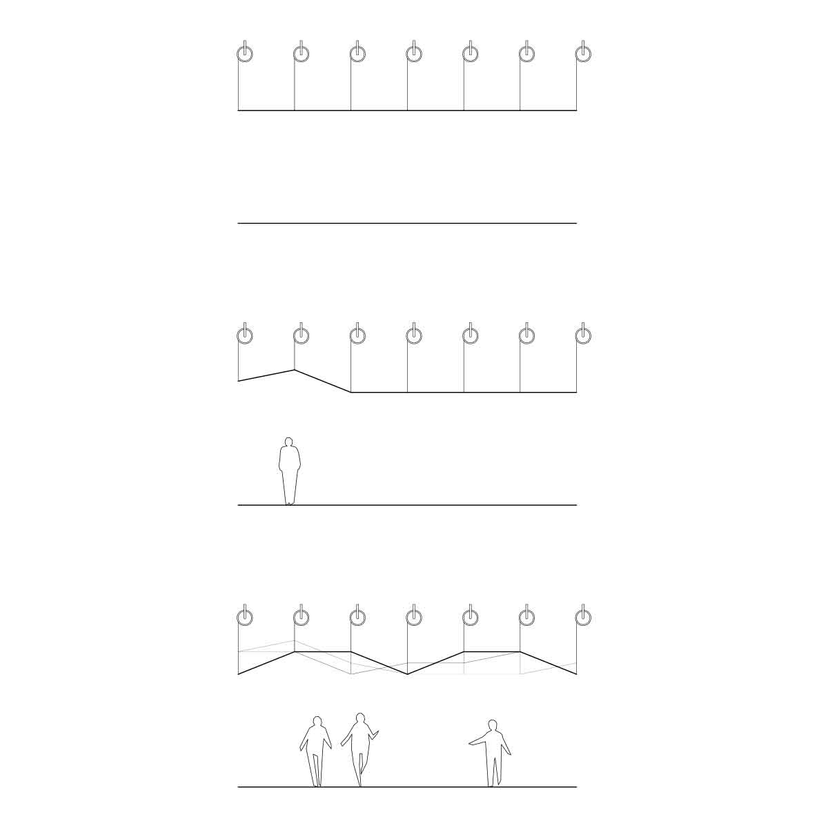
My passion for human interactivity in space lead me to the idea for this installation. I've been facinated by the work of French multimedia artists Adrien M and Claire B, engaging art with the movement of a viewer. As people dance below the installation, the installation responds, changing topography and color.
Here I played with live interactions using a firefly plug-in in grasshopper access my webcam. I used R values in the live video to determine circle widths.
This is a sketch of how the interaction might look with takeup reels.
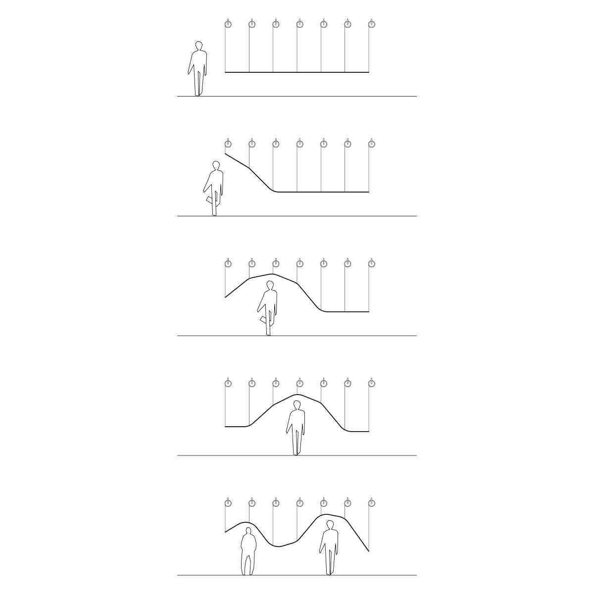
I also had an alternative idea for a more imersive experience, holding the fabric at waist level obscuring views, detecting the motion of the user allowing them to pass through but not to touch. I thought the idea was beautiful for the meditative space it created and interaction that was truely engaged with the user but it seemed to complex for the time being.
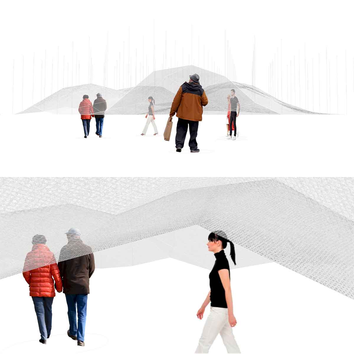
This is a render of the aforementioned idea.
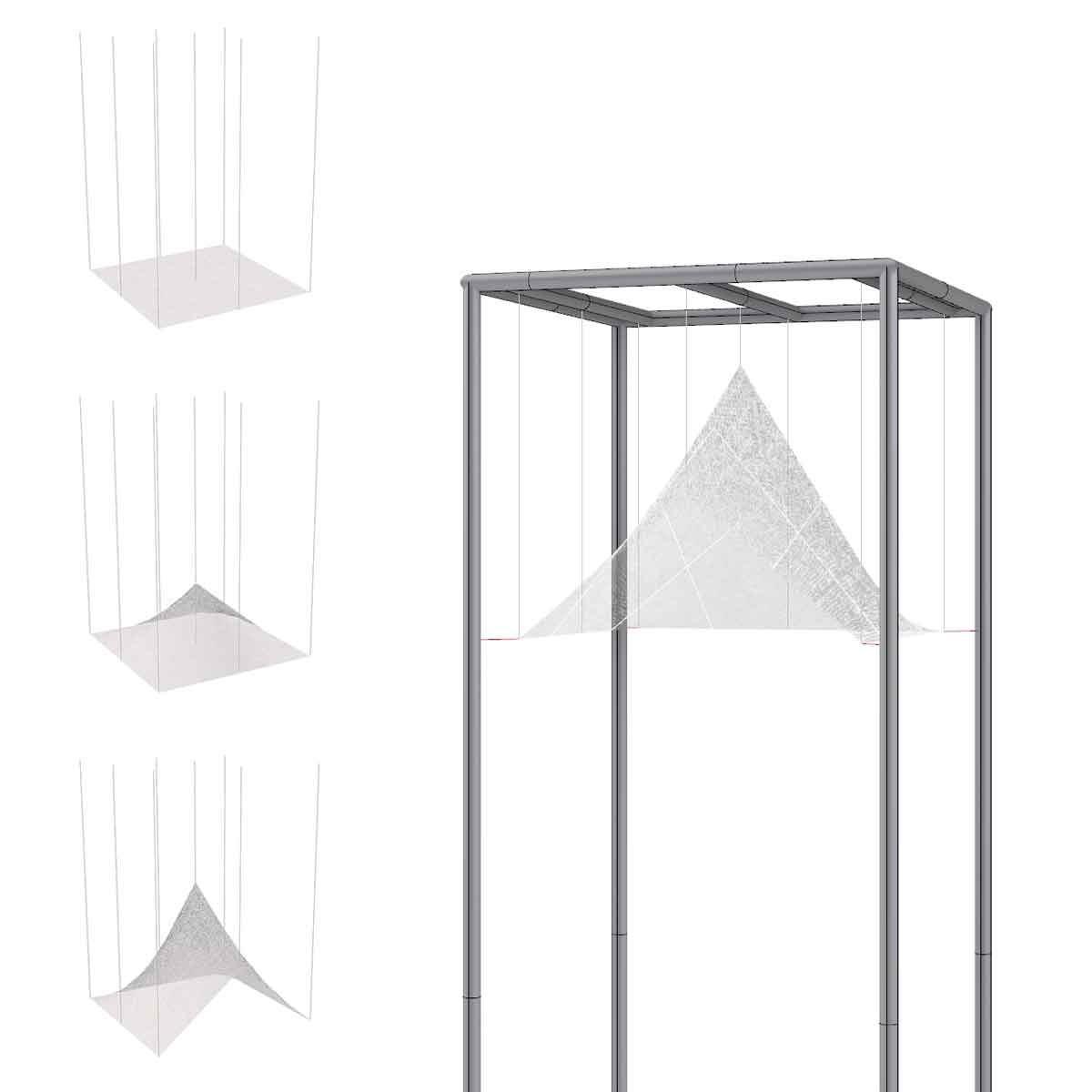
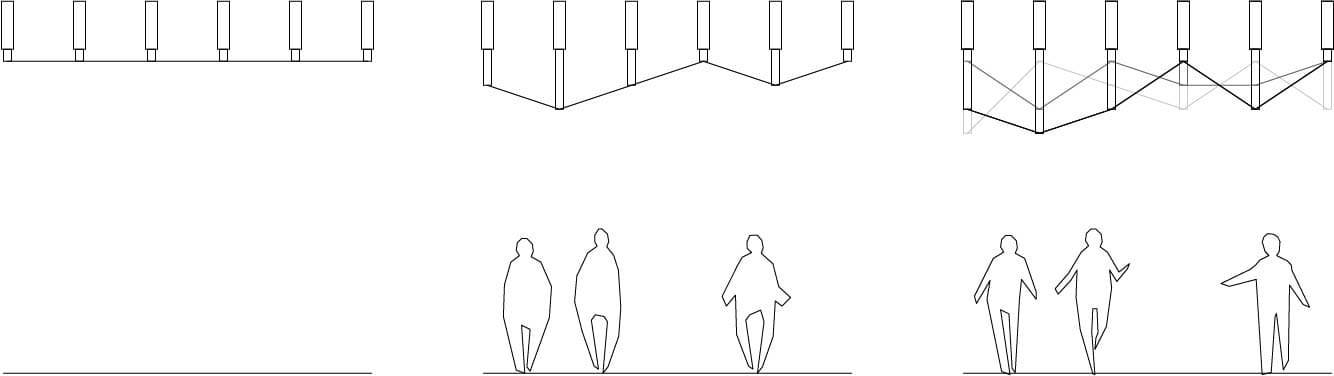
I ended up pairing down my idea to a simple 4 panel interaction with 5-9 servos, showing a unit occupiable by 1 or 2 people.
This is my sketch of what I think the physical piece will contain
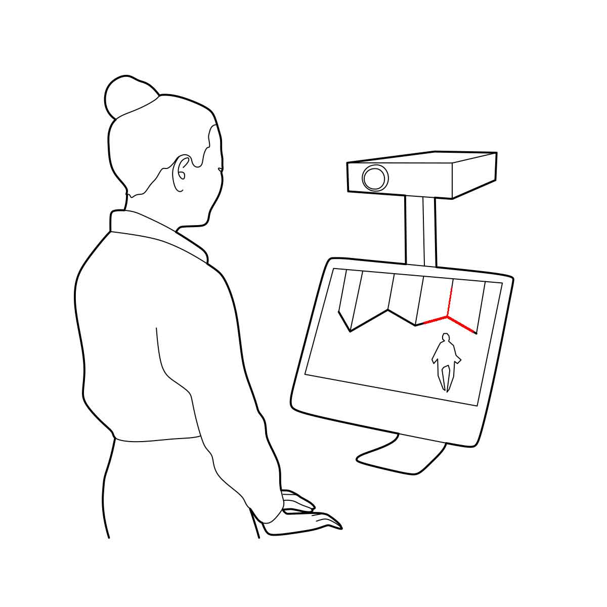
I also plan to have an attached AR display of the full system highlighting the physical component
I began to play with my imagined responsive movement, using alpha values from my live webcam input to control the length of digital cords via grasshopper.
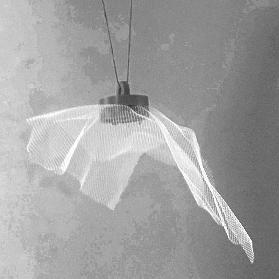
I then modeled the movement of the cords and fabric at a smaller scale.
I created a model in grasshopper that used my webcam and mic to influence the movement of these cables. Luckily there is an arduino component in firefly (the plugin I used to make my model) So connecting my components should be easy enough.
Here's a behind the scenes of the webcam only version.
and here is the mic (volume = frequency of sampling) + webcam (pixel variation aka movement = degree of movement) script
Sketching
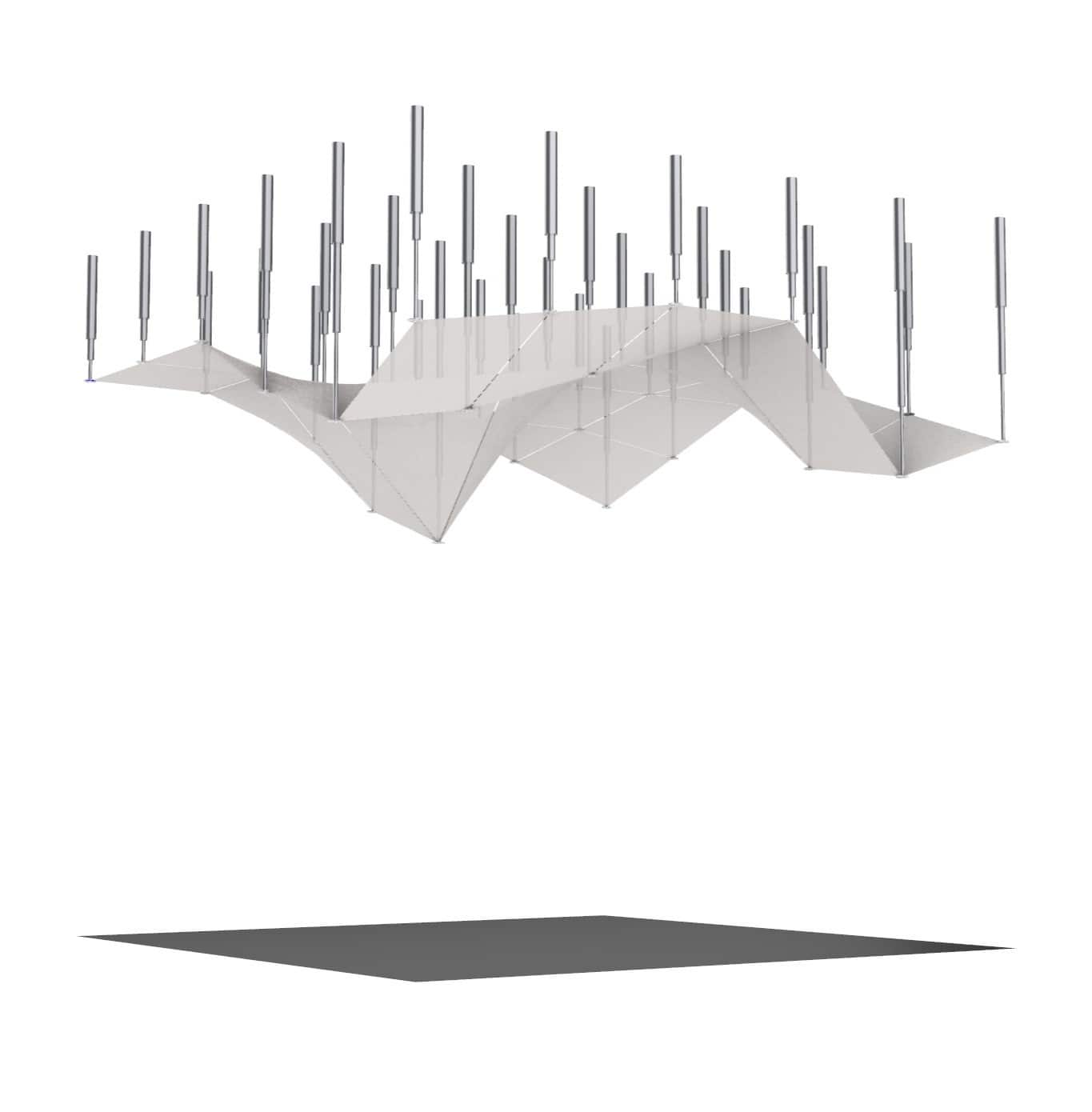
To configure the movement, I considered the use of a series of pistons, pushing and pulling against fabric panels.
After conversations on timeline and strategy with Neil Gershenfeld, I was advised to use a takeup reel rather than rigid pistons. I realized I could combine the aesthics of the piston and simple logic of the takeup reels by using the pistons as hollow channels much like a toy lightsaber. However for now I'm just focused on getting the components for the reel working.
.
As a reminder, this is the concept sketch of the assembly
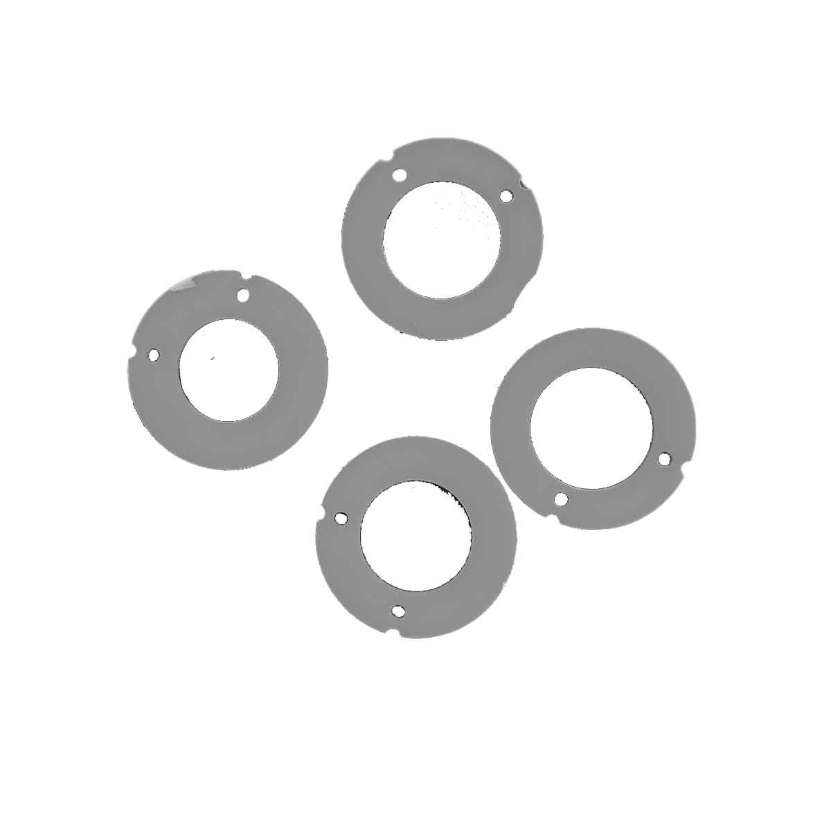
I realized the need for cross bracing and used the laser cutter to produce these disks to attach chain/wire to the poles. Because of nominal sizing and the difficulty of measuring a round object, I tested 4 seperate measuerments (each varying within 0.01") to find the perfect fit.
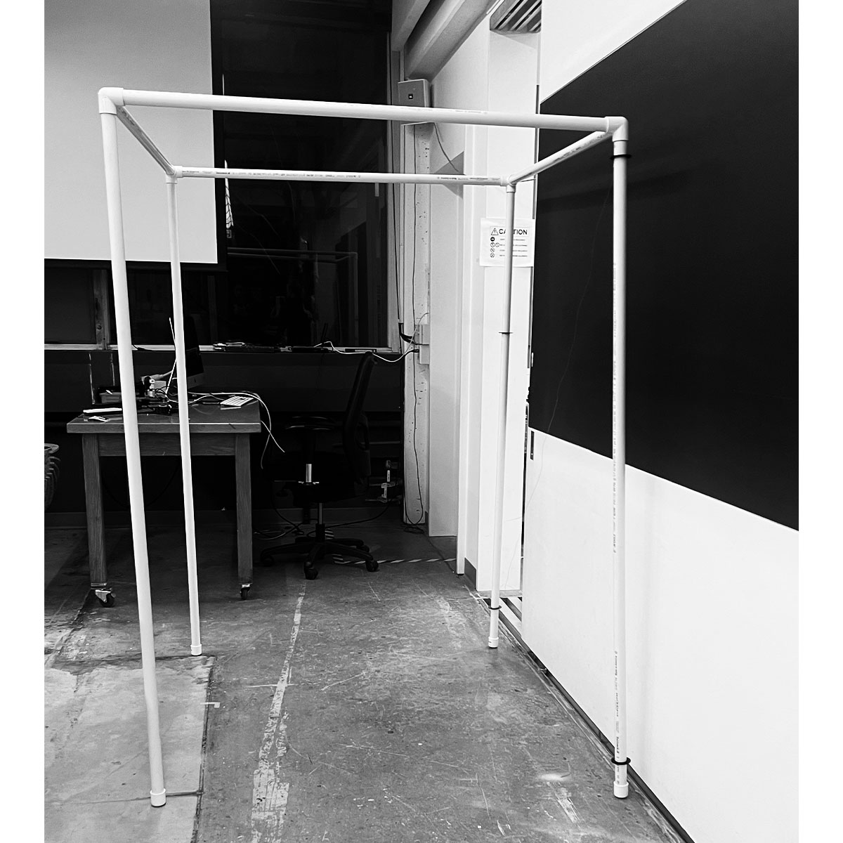
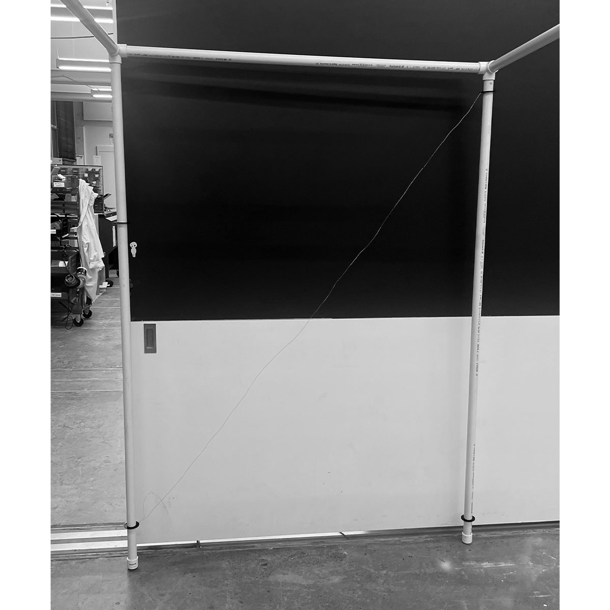
I fit the laser cut rings to the pvc system, setting it up in the science center lab. Without the cross bracing it toppled over several times.
I tied some temporary wires to the set up.
I was learning my lesson about the fragility of tessioning, but felt confident it would work out.
Things were not looking up with my ESP32cam so just in case I switched to a webcam based systems. To hold the webcam I had to create a case. I modeled it in rhino.
I 3d printed my model.
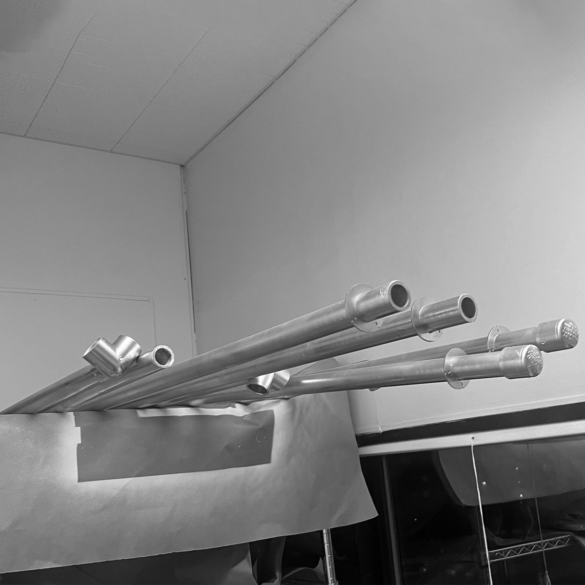
I spray painted the pvc poles and attachments silver, to make them look more elegant.

This is a photo of the model set up
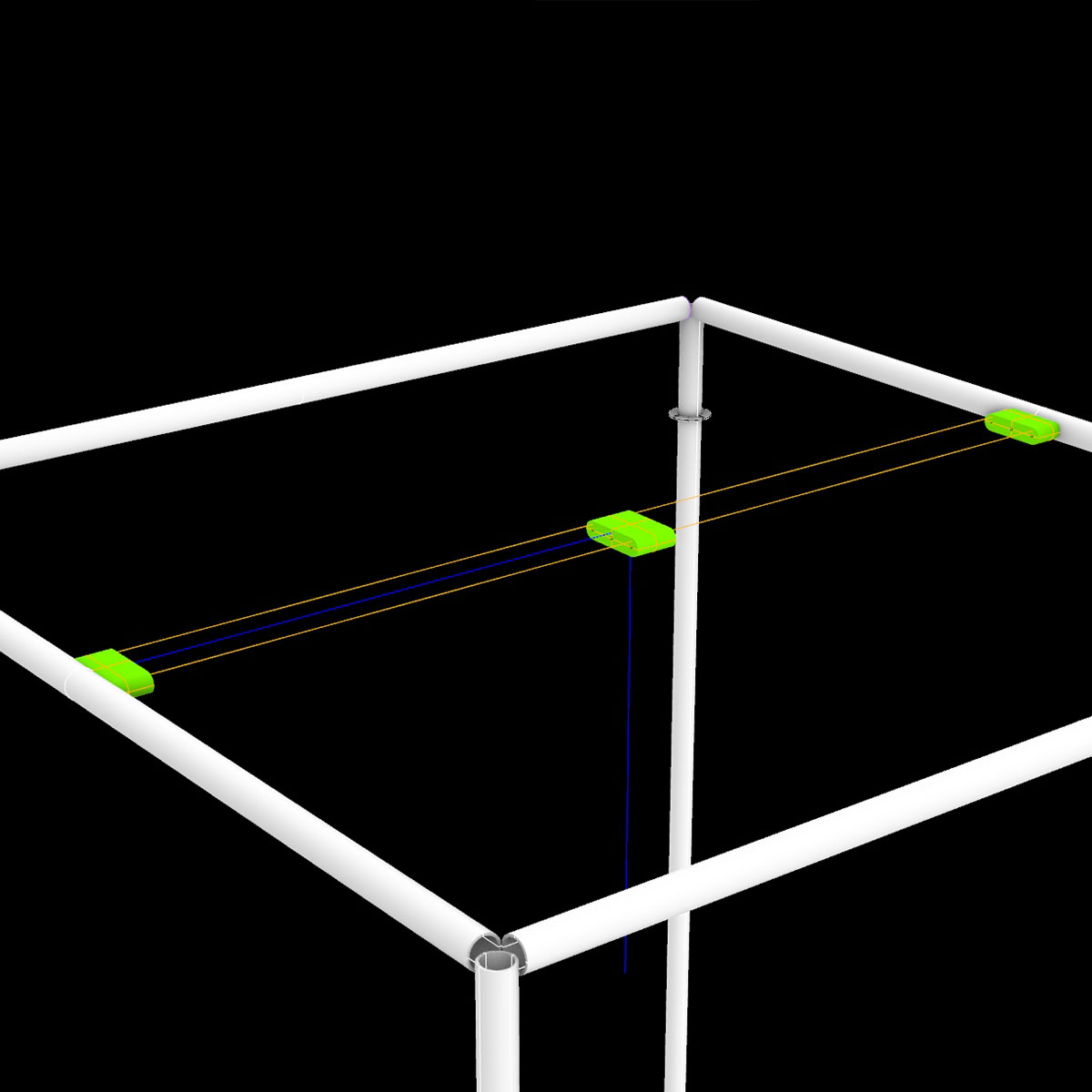
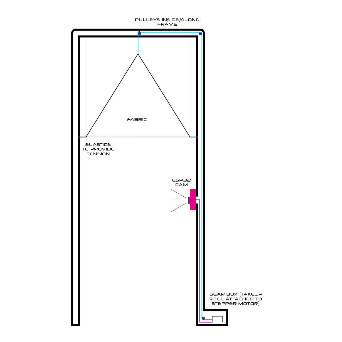
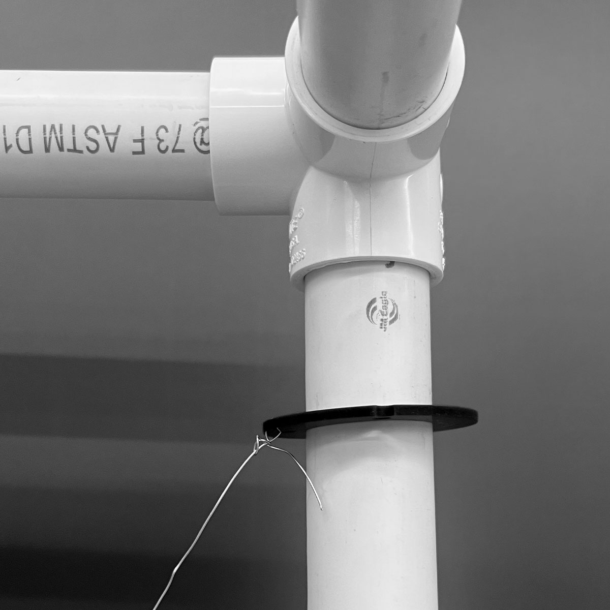
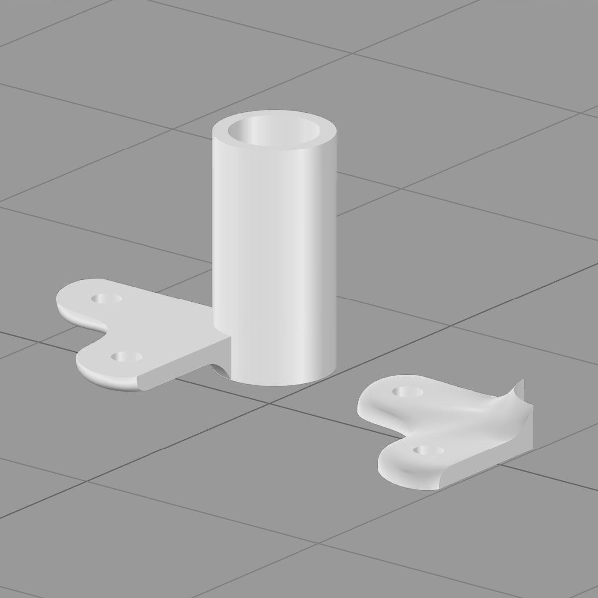
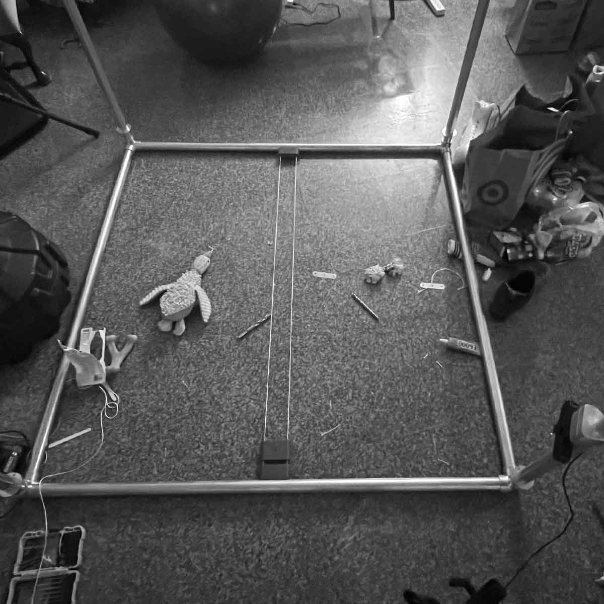
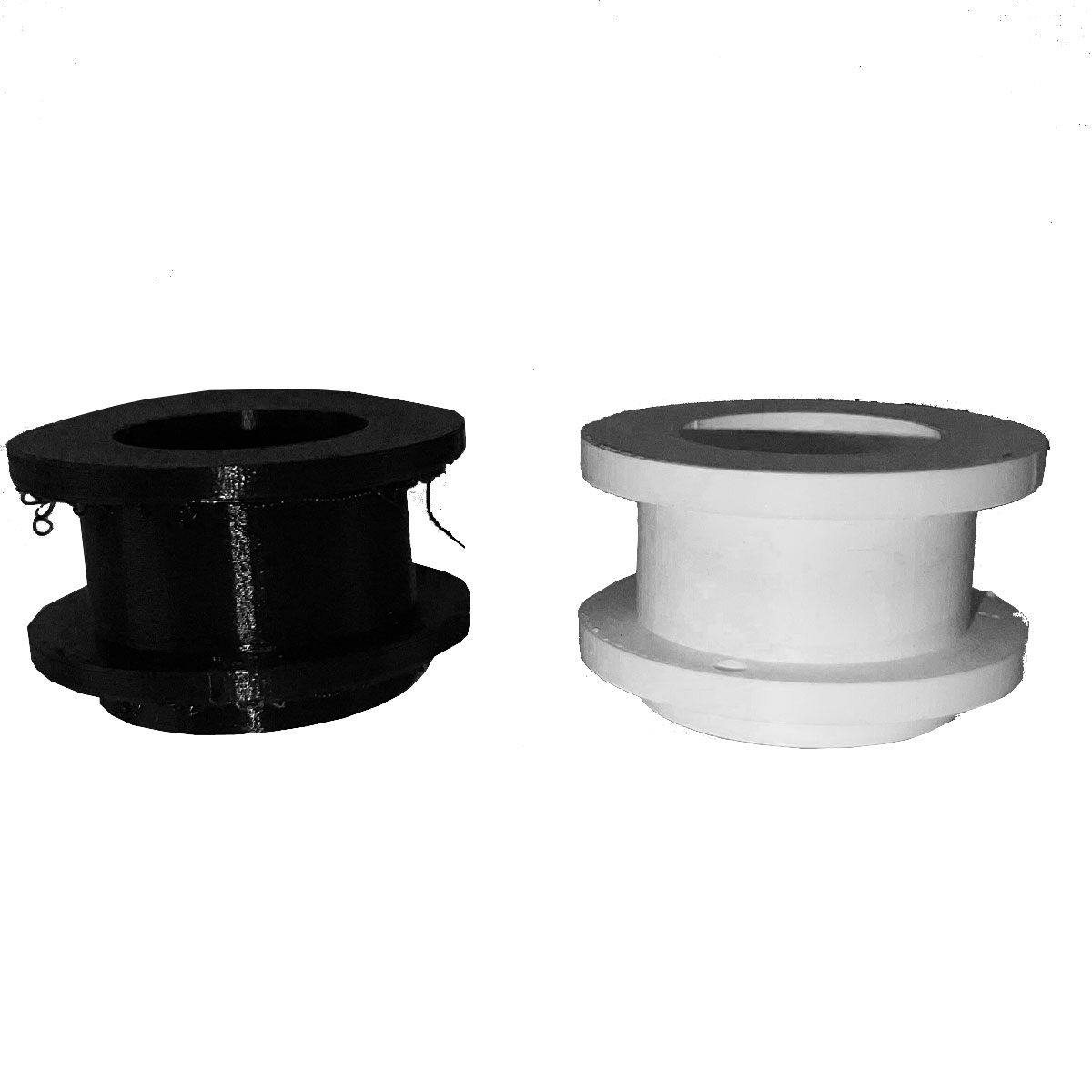
I wanted the framing to be as lightweight and minimal as possible. I designed this system that includes two stationary cords (pictured in orange) to keep the system stable. The blue cord runs up the frame and out this minimalist system through a hole in the bottom of the center print, being pulled by the motor on one end and pulling up the cieling pannel on the other.
The cords would be made of fishing line while the guides (green) would be 3D printed.
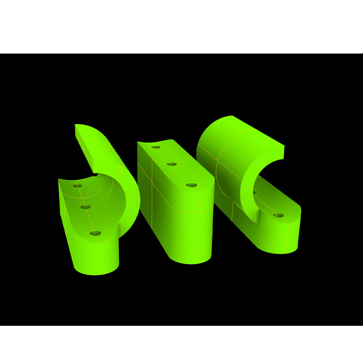
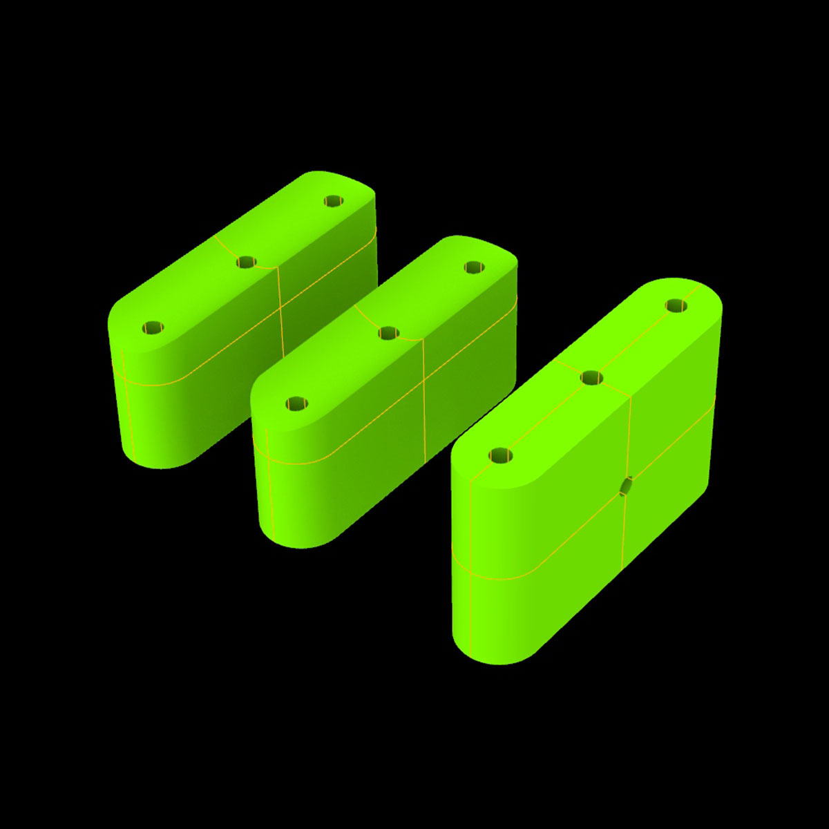
The rails seemed woobly so I rededigned them
I began to design an attachment for the tule fabric to connect to the fishing line of the takeupreel.
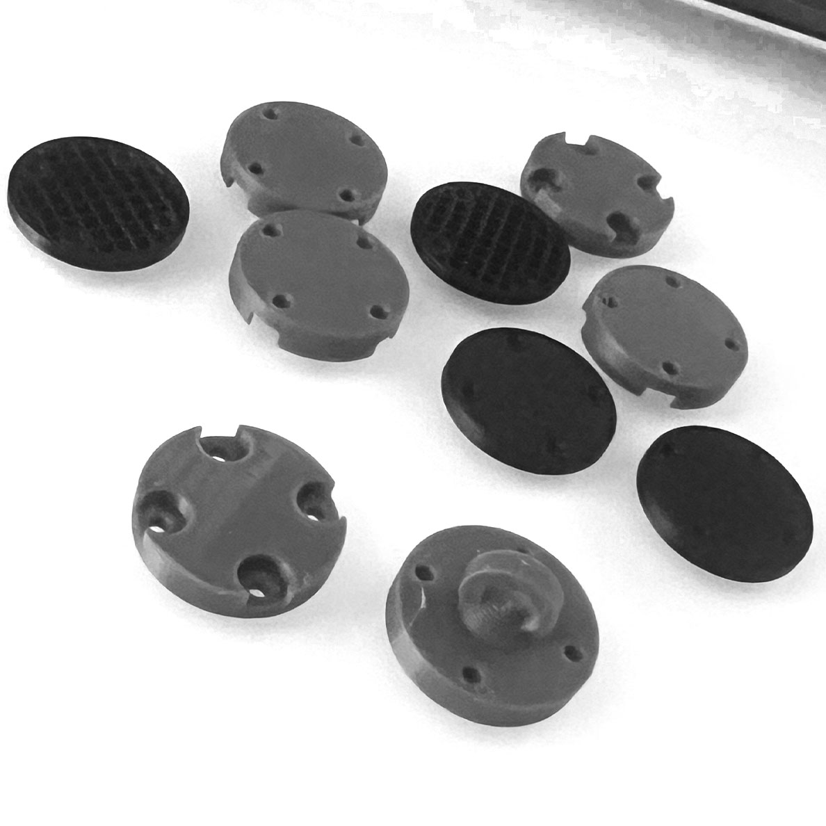
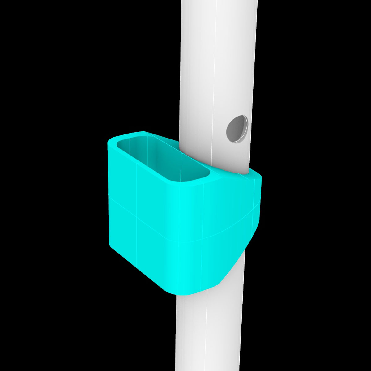
Ultimatley, I settled on this 2 part button design. The lower portion has indentations on the side facing inwards towards the fabric in order to hide the knots which can be seen in the following photo.
The resulting design is secure and elegant when sewn to the delicate tule.
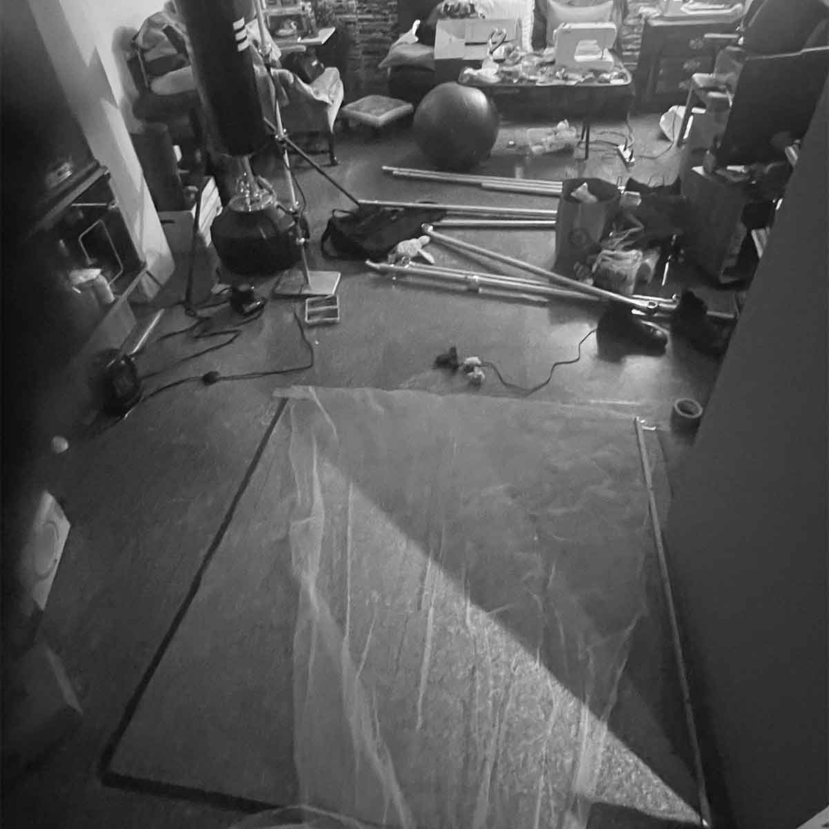
I brought the structure home realizing the lab was getting too crowded. I was sewing, painting, drilling and sawing.
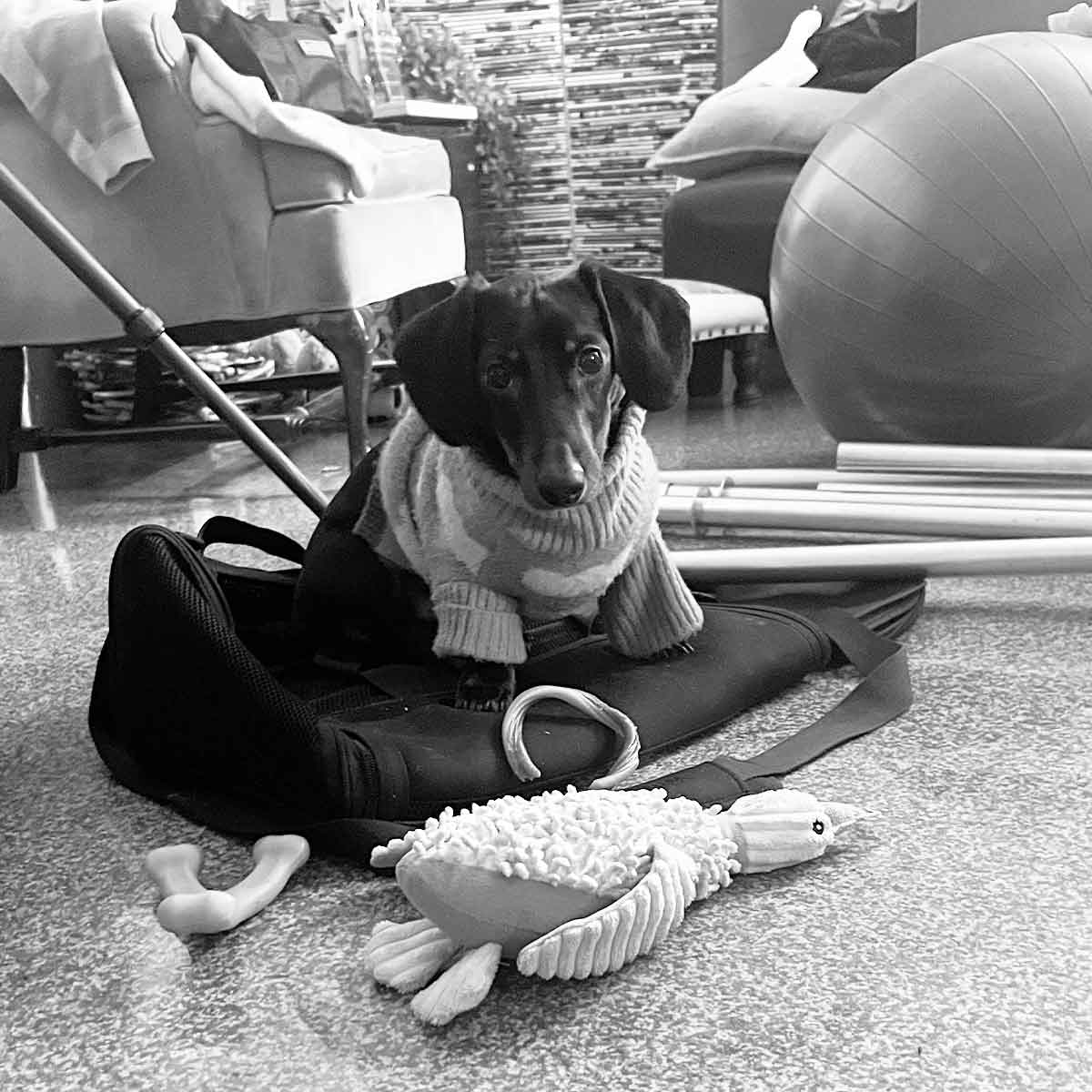
Frankie of course is judging.
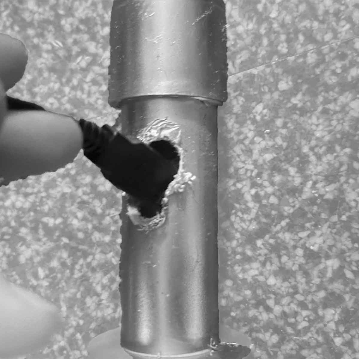
I faced some miscalculations of the size of the hole needed not only to fit the head of the wire through but to angle it downwards to run it through the frame.
This image shows the 3D printed components, Frankie's chaos, and mine.
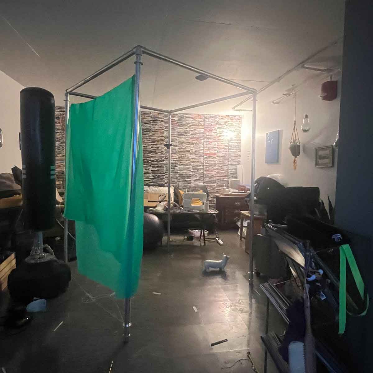
Rather than a direct motion capture script, I chose to process the number of green pixels in frame to better identify the density of people and speed of movements. I hung up a green screen on the cross bracing.
.
I was excited to continue on. I had the stepper working on the breadboard. (refer to output devices for more detail on that.
I really put my all into it...
Large Scale Modeling
Modeling was providing a lot of information that was informing my design along the way. I was exercising new skills like sewing. Learning cross brasing, etc. The whole process went rather smoothly, minus the electronic components. I was excited for what I might produce and i really put my all into what I knew I could accomplish assuring myself that the electronic components weren't too hard. Eventually, I would figure it out.
...
but then I began the process of
learning to give up
My first mini "giving up" was the realization I had to move beyond the sunk cost of all the time, effort and money I put into the full scale project. The more it stayed incomplete, the more it taunted me and I wanted to be done as soon as possible
I just wish I had been more realistic about my abilities sooner. I just thought it was so easy for others: it should be easy for me. I was wrong. So wrong.
I at least appreciated Nathan sat down with me and said he was conveying how hard I was working to Neil (prior to me getting covid), how I was there for every office hour I could and almost lived in that fab lab, trying my hardest.
I got covid which was fine at first and then foolishly decided I was healed enough to still go hiking in Peru for the New Year where I got such violent mountain sickness (happens when you live a life at sea level and your lungs aren't back to full capacity yet). In my stuborness to push through it (a clear trend) I became a lot more sick than necessary. As soon as I recovered I was back in the lab.
Insert other circumstances such as January building maintance and the panic I had when I got an email that I was failed as opposed to given an incomplete (miscommunication..etc...etc..)
and I decided:
IT'S TIME TO GIVE UP on having the life size version of your project
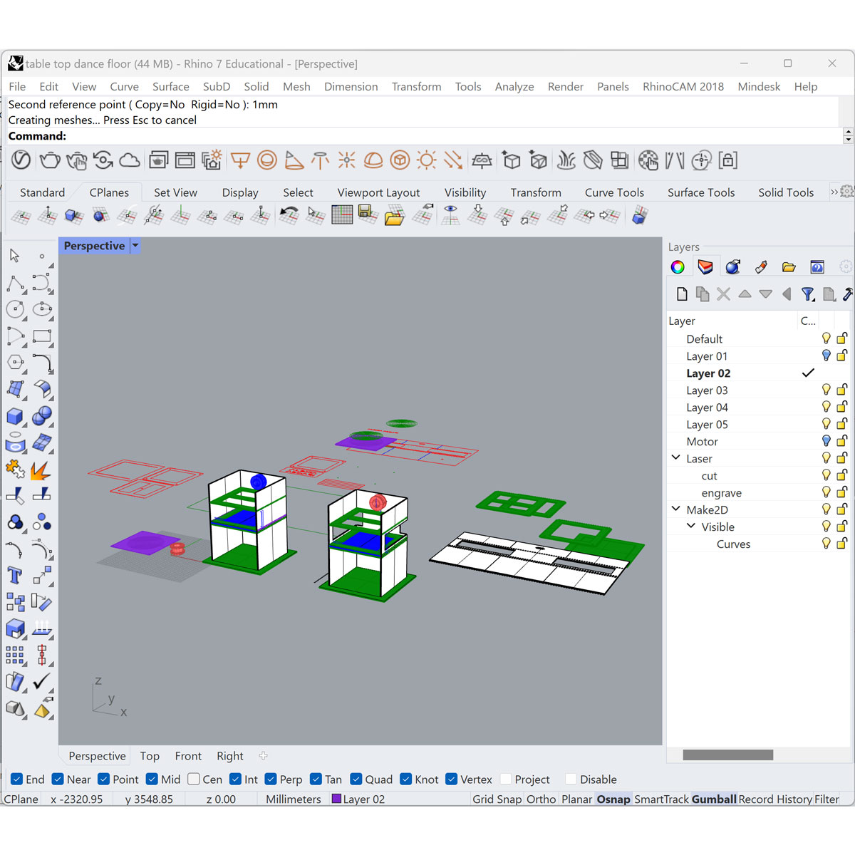
I began by designing the model in rhino.
Access all final files including the model by clicking here
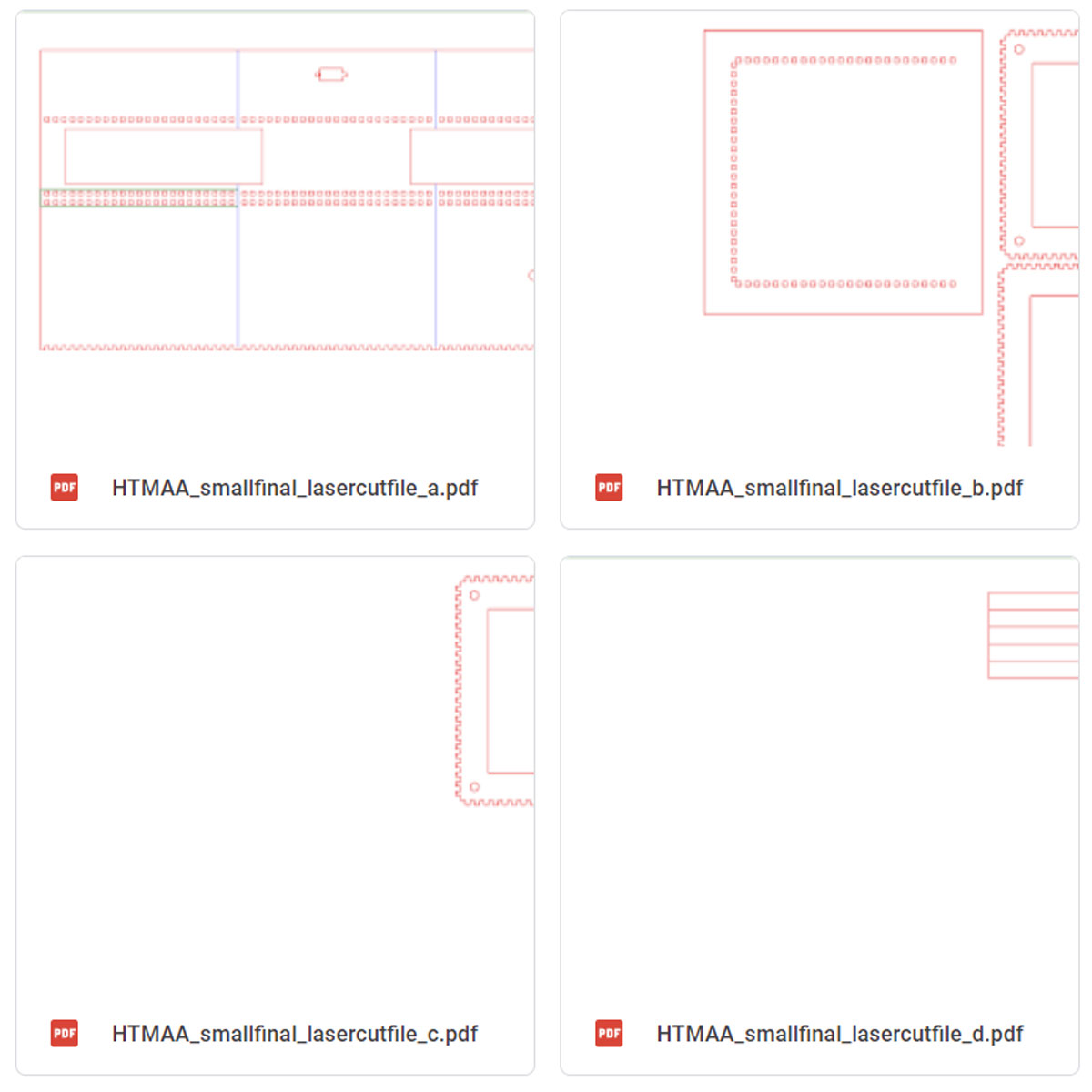
Laser cut PDFs can be found in my archive drive. I tried to use principles from first semester like box joints and folding when possible.
The image above is from my dedicated HTMAA goggle drive archive.
Access those laser cut files by clicking here
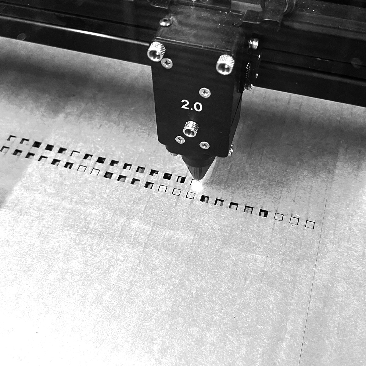
Lasercutting went smoothly. I used mat board parameters on cardboard. I had to get creative with positioning scraps to get my cuts at times.
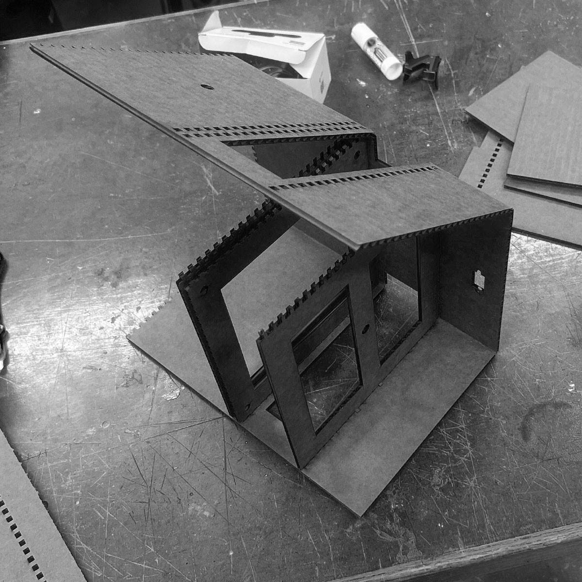
I folded the main piece and slotted in the levels between.
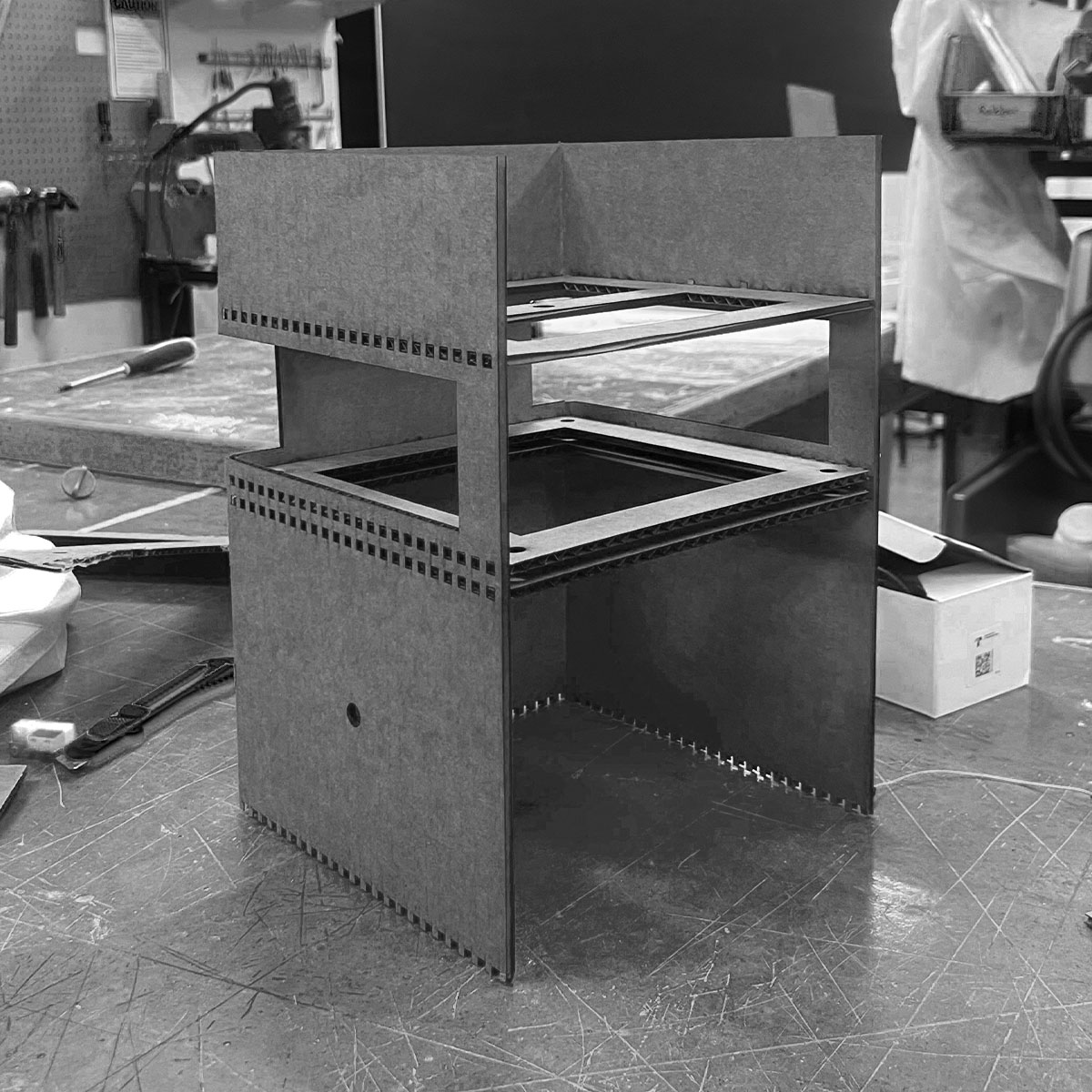
Because of the box joints, I was able to assemble all the pieces together without glue.
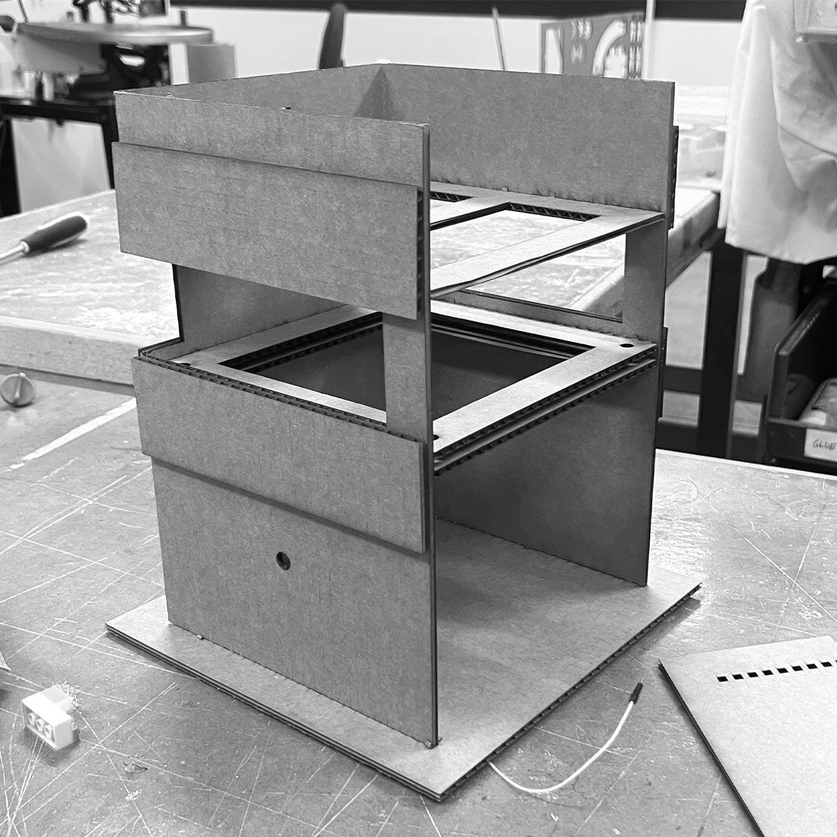
I still added hot glue to be sure and extra rectangular pieces to cover up to sloppiness (protip)
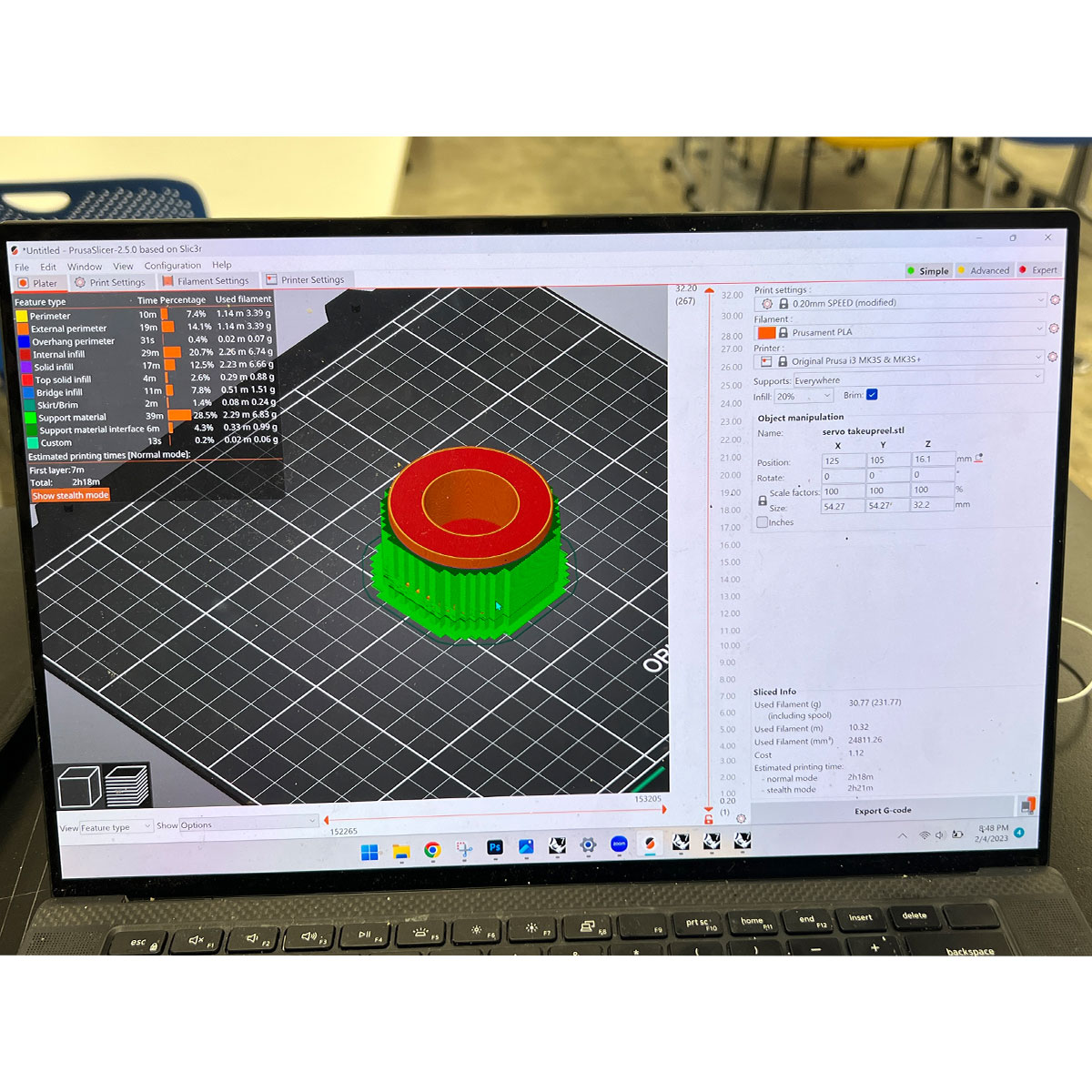
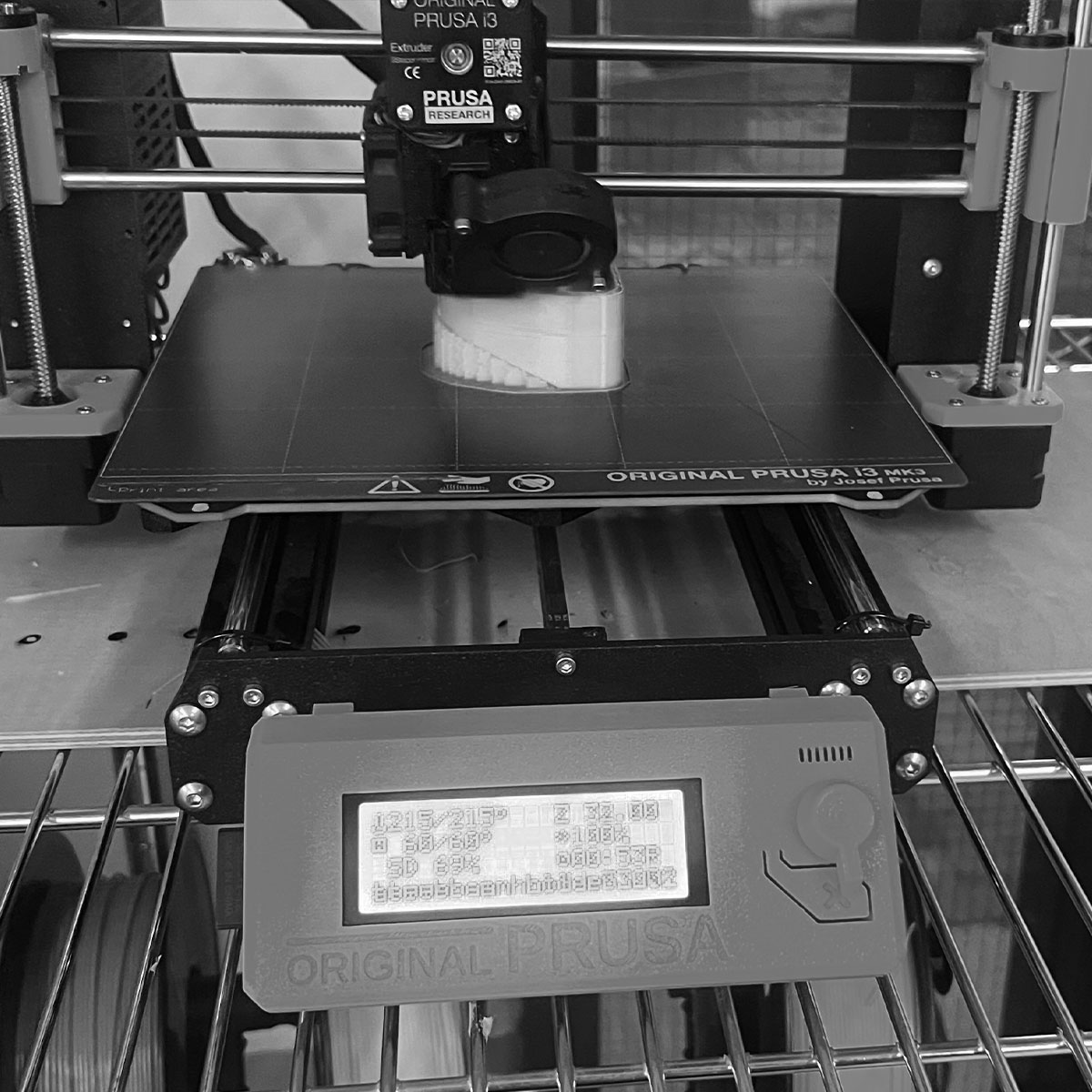
Now it was time to print the takeupreel gear. I designed it in rhino based on a servo file I found online. as the servo can only move 180 degrees, half of the circumfrence should be greater than or equal to the distance the string needs to move.
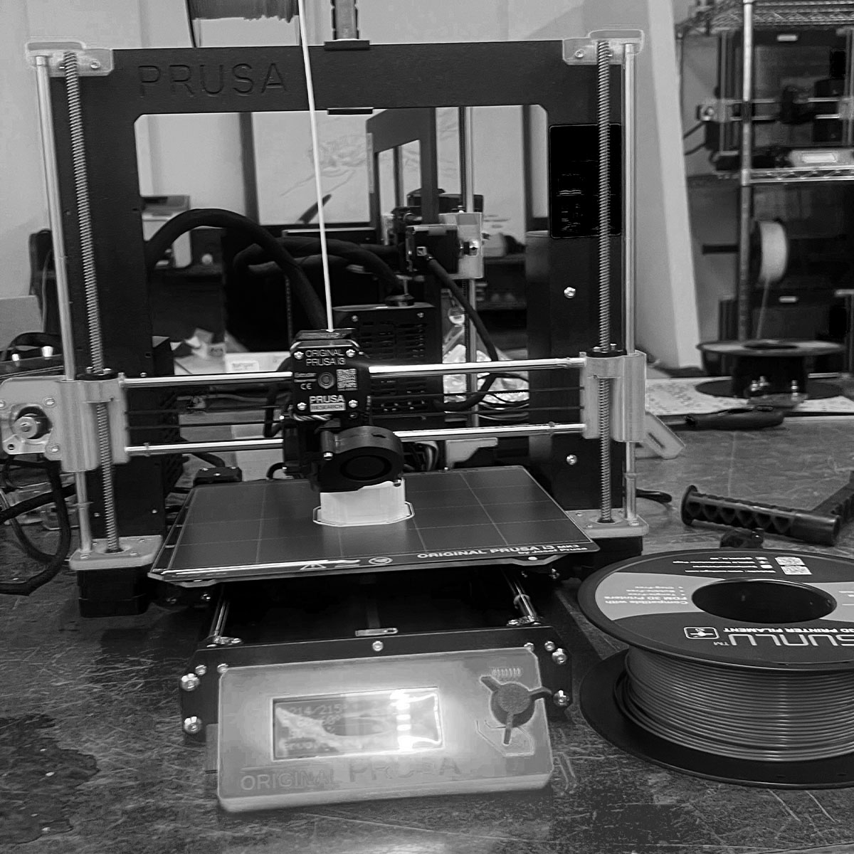
The printing went pretty quick as I kept the infill light.
The one printed with supports clearly printed cleaner.
Borrowing from my originally intended direction from wildcard week, I tried to laser cut the structure out of a more rigid material:acrylic.
Unfortunatley, it was too rigid.
At least I knew the dimensions work as the panel was able to slot in.
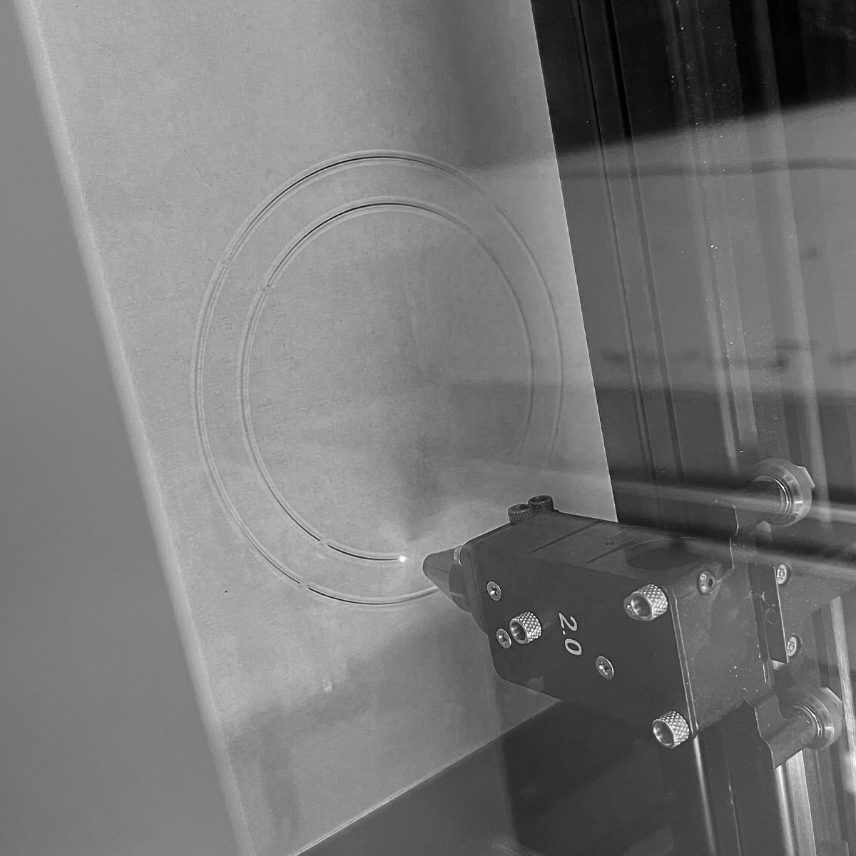
I took inspiration from Kassia's 3D printed textile explorations.
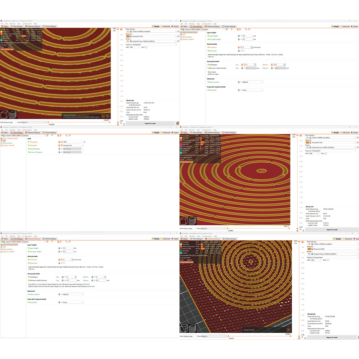
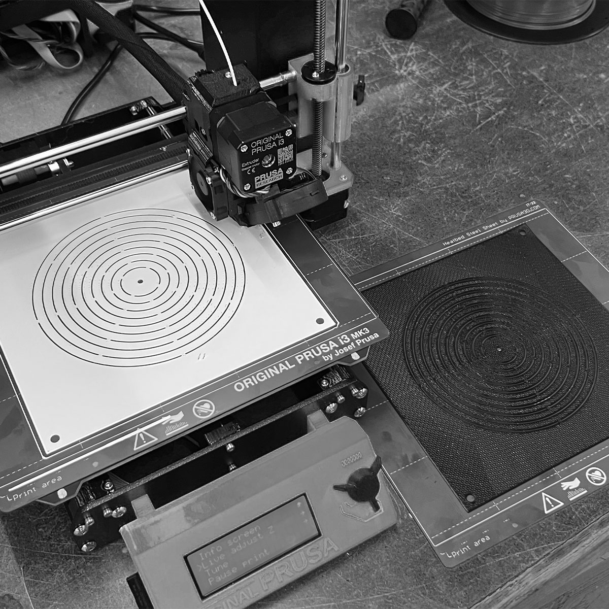
I prepped a few files that were one millimeter tall, some solid the whole way through and others just infill (zero solid top and bottom layers, 6 solid side walls). While the file was set to 1 mm I found myself stopping the print after the first few layers because of the rigidity of the PLA.
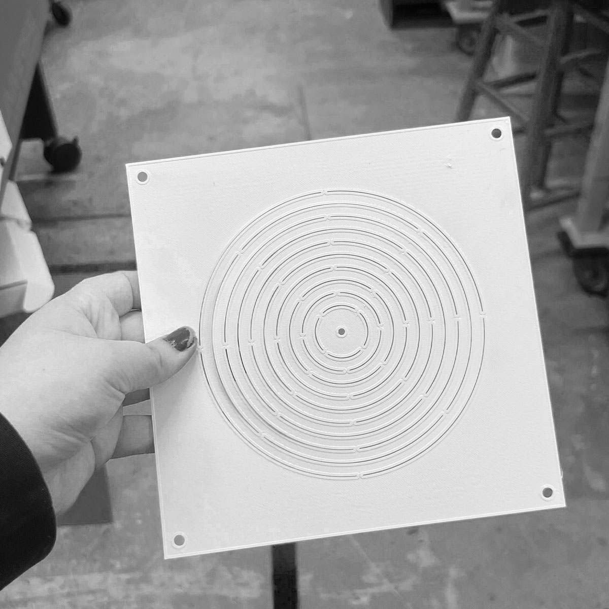
This piece was a solid print stopped after the first 3 layers. I explored various infill patterns and densities.
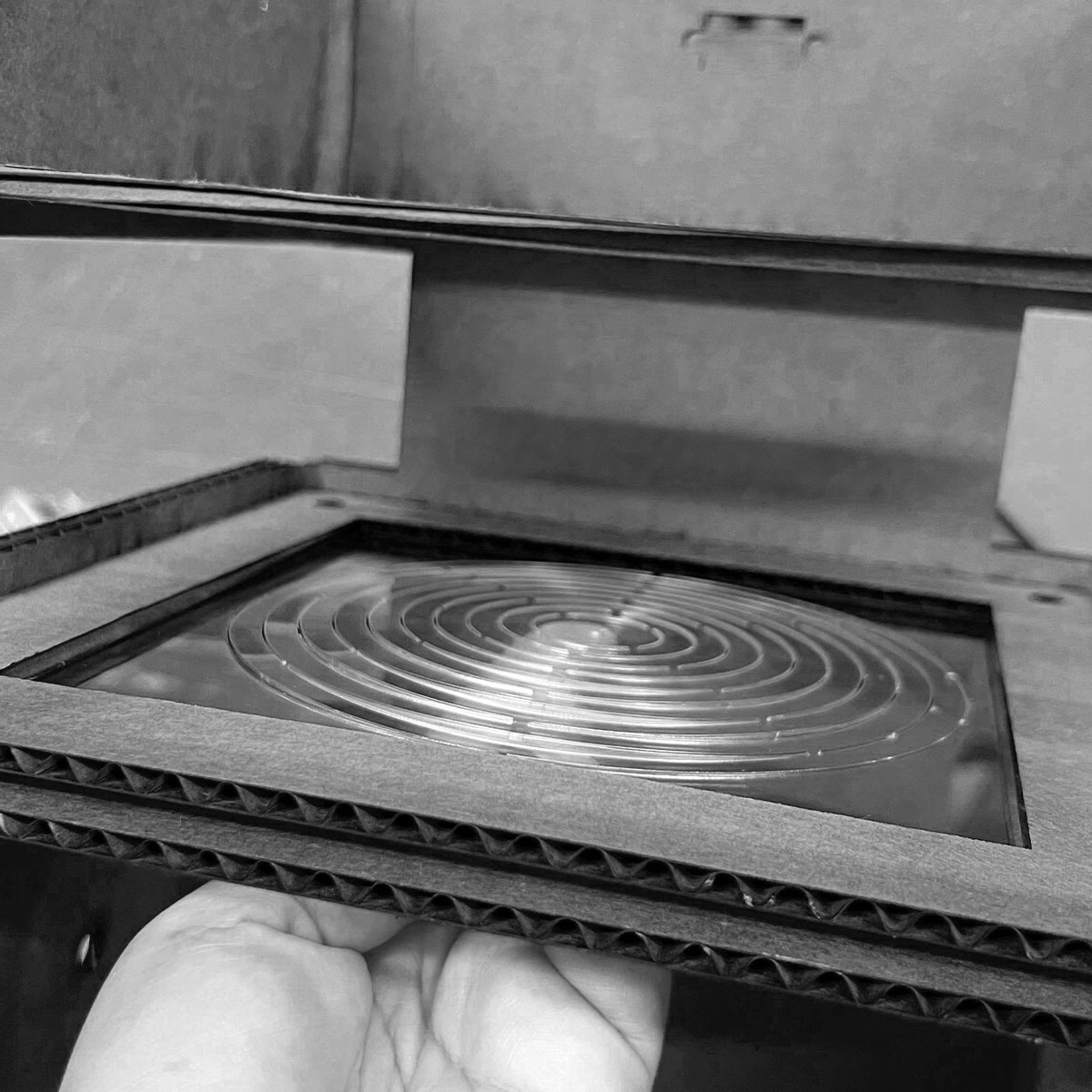
There was a delicate balance of when the print bed had cooled down enough to safely remove the print without warping like in the image above, but not too cool where it was difficult to seperate without damaging the thin layer.
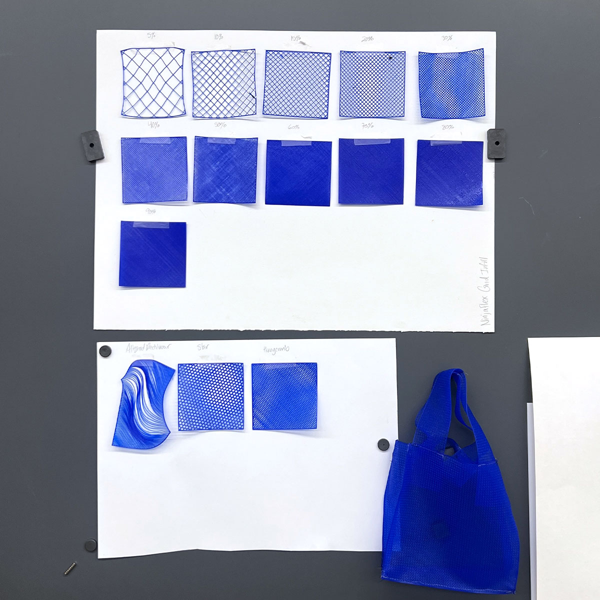
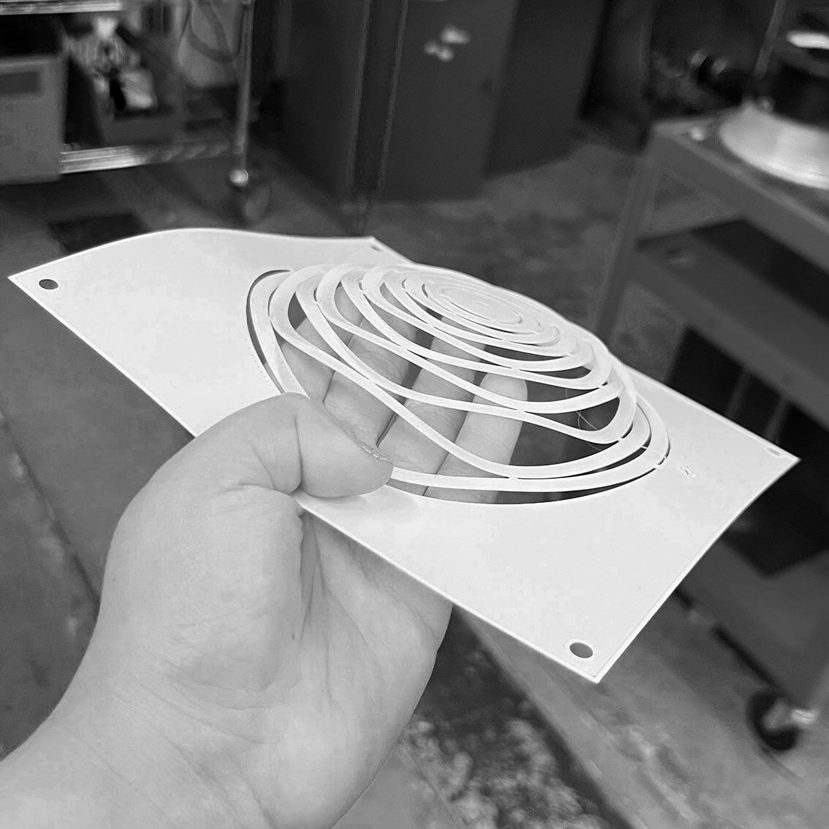
Here was a sucessful test, with one of my sparsest infills (40% in a star pattern on the prusa slicer)
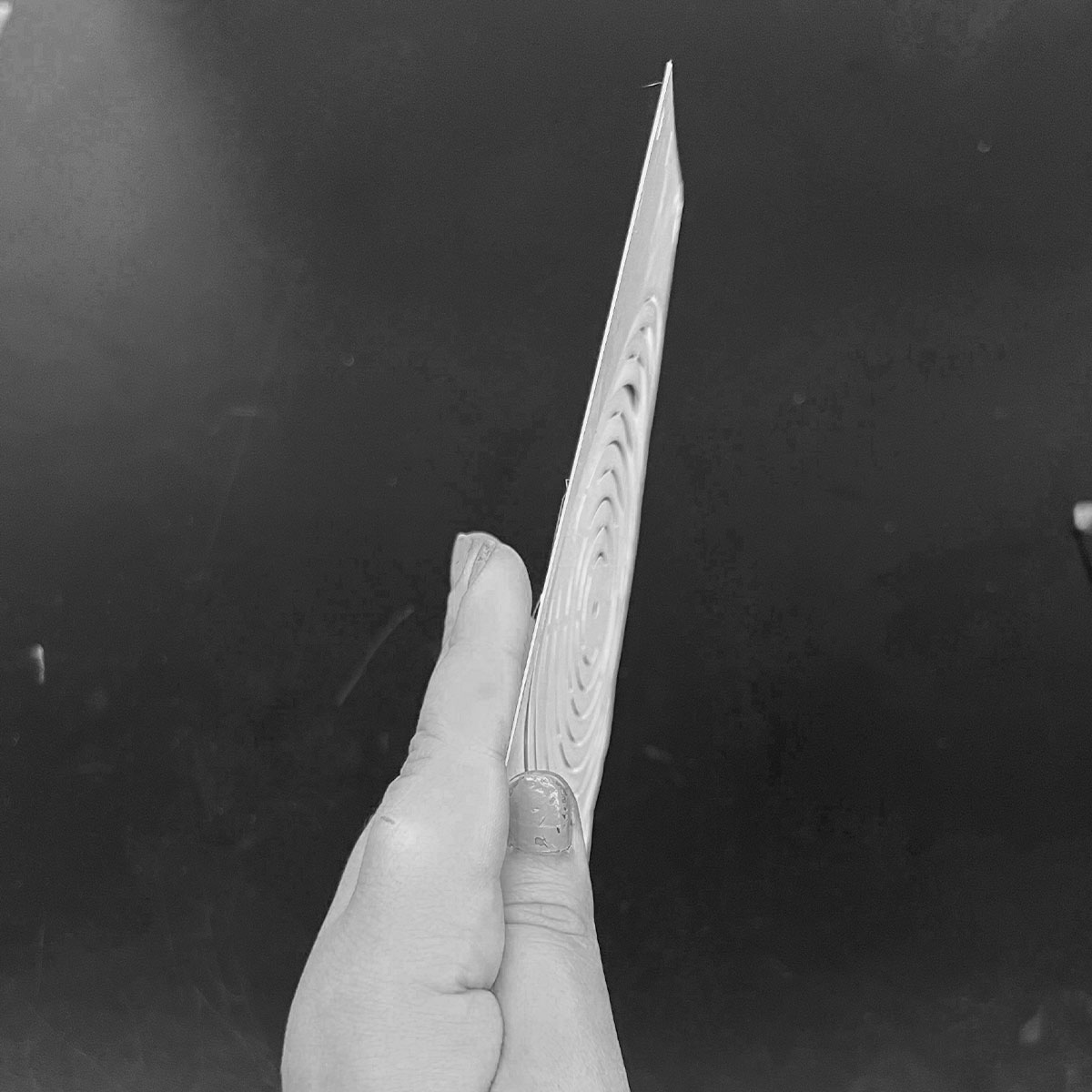
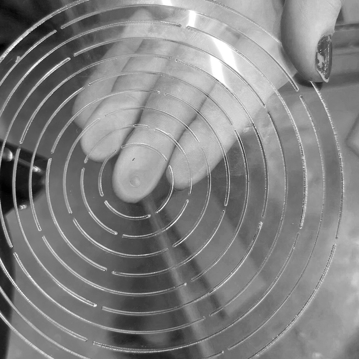
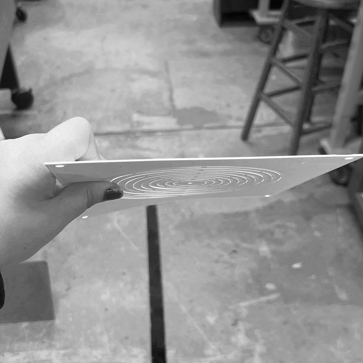
I found the best flexibility was achieved after 1 layer of PLA. It was suprisingly strong.This picture actually shows 2 layers of thickness.
Here is the flexibility of the honeycomb structure at 2 layers of thickness.
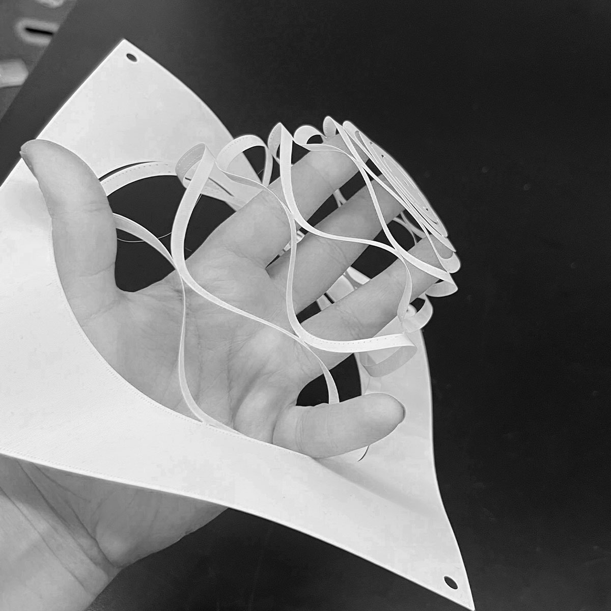
At only one layer the structure was very flexible.
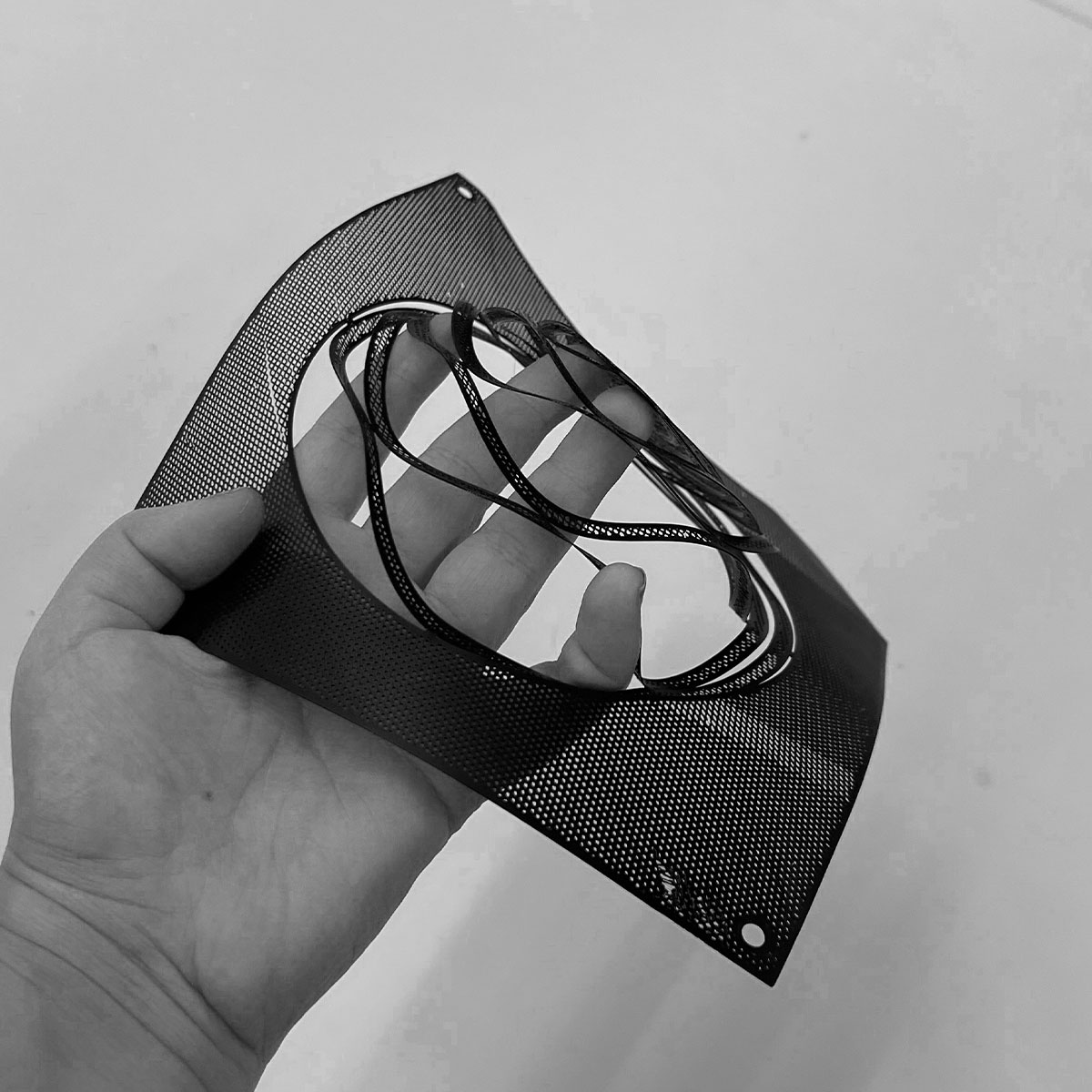
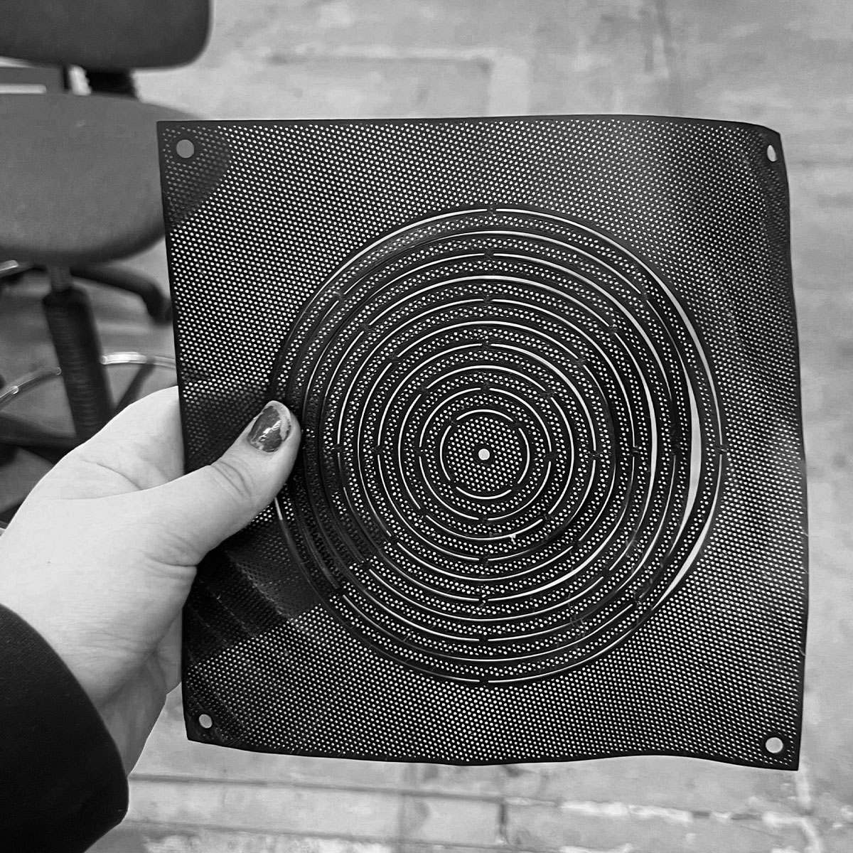
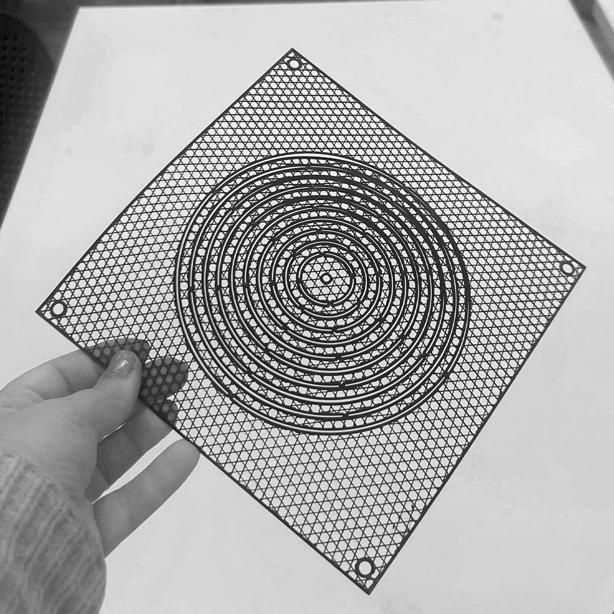
The patterned infill structure plays with opasity nicely.
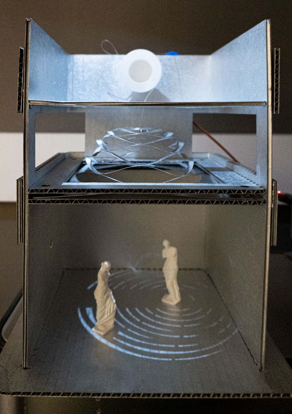
In a final mini printer task, I printed these small statue of venuses at low res for quick scale figures in my tiny scale model.
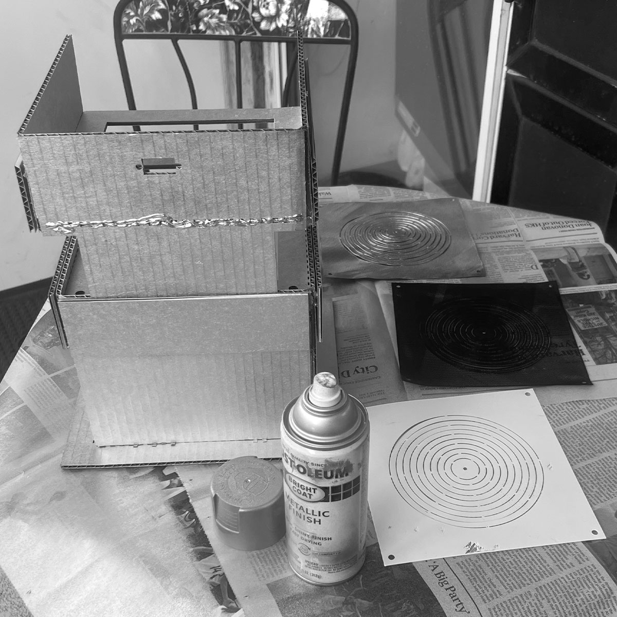
I then set out to spray paint everything with the left over spray paint from my initial idea so the materials looked homogeneous
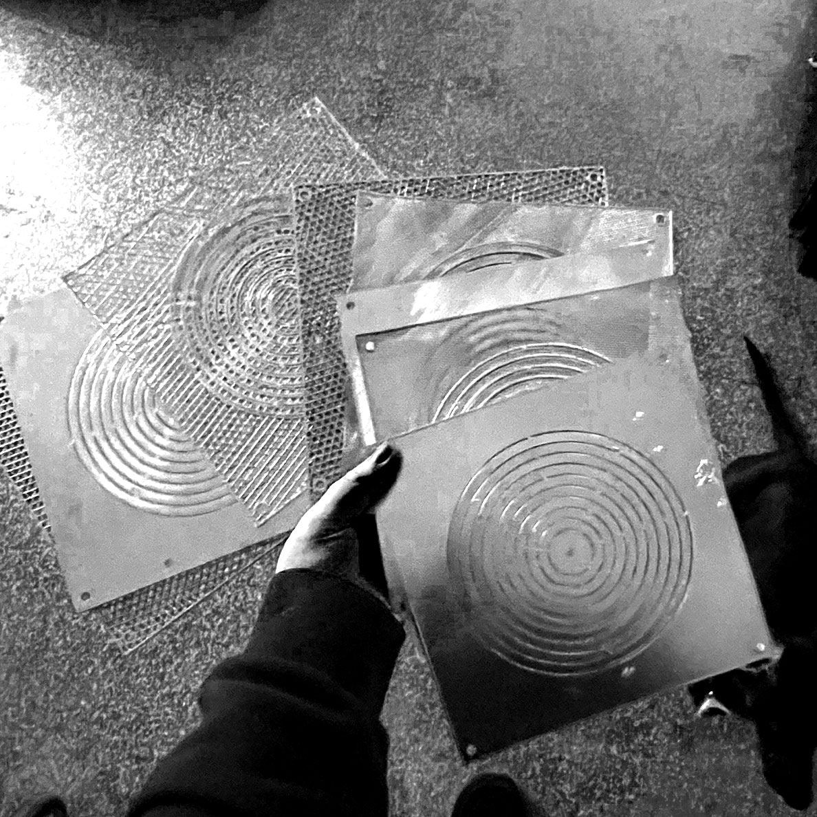
I was left with all these screens of various infill patterns, densities...
...and widths (also notice Frankie observing my design process)
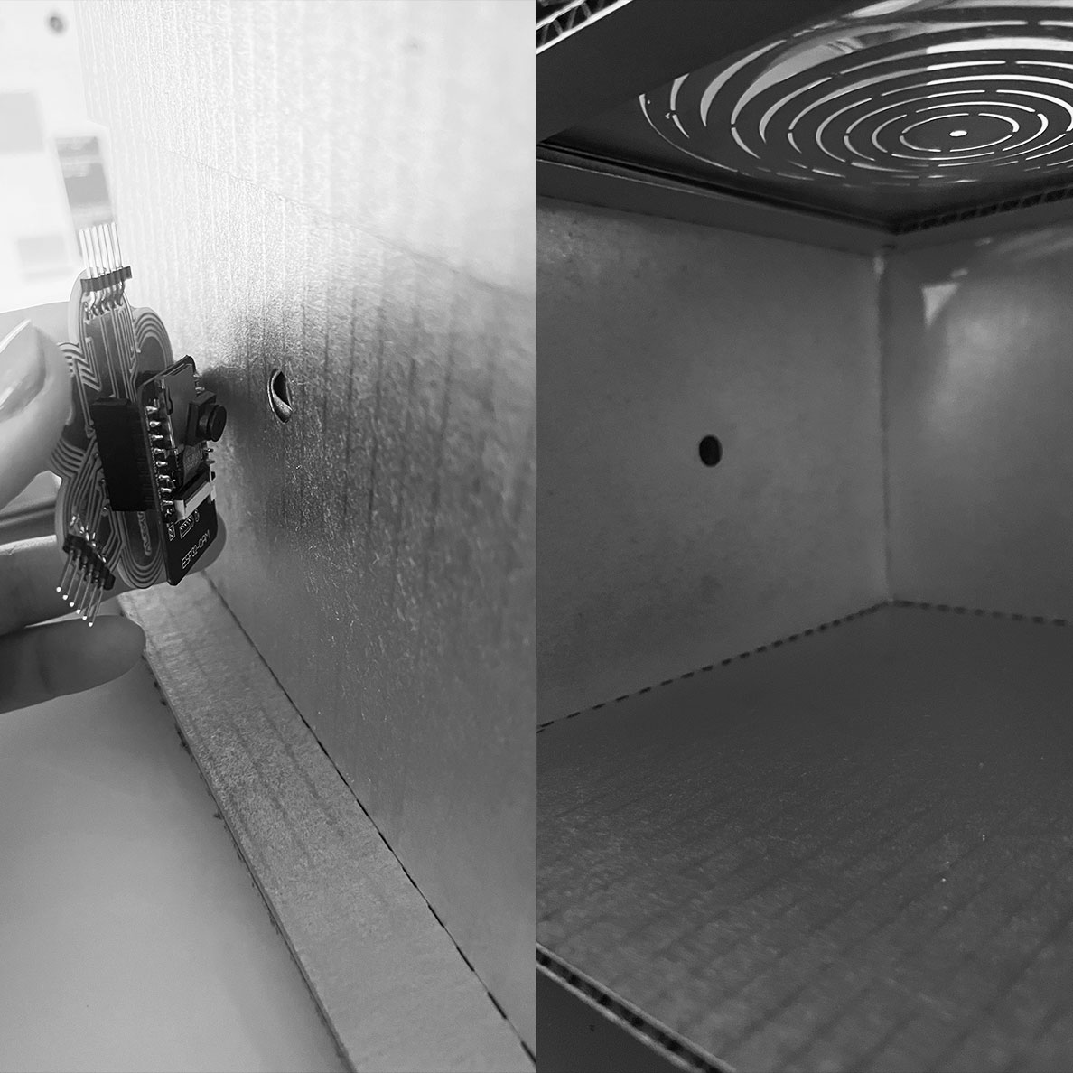
Also, a small detail to point out, there was a hole made in the wall specifically for the esp32 cam to peer in.
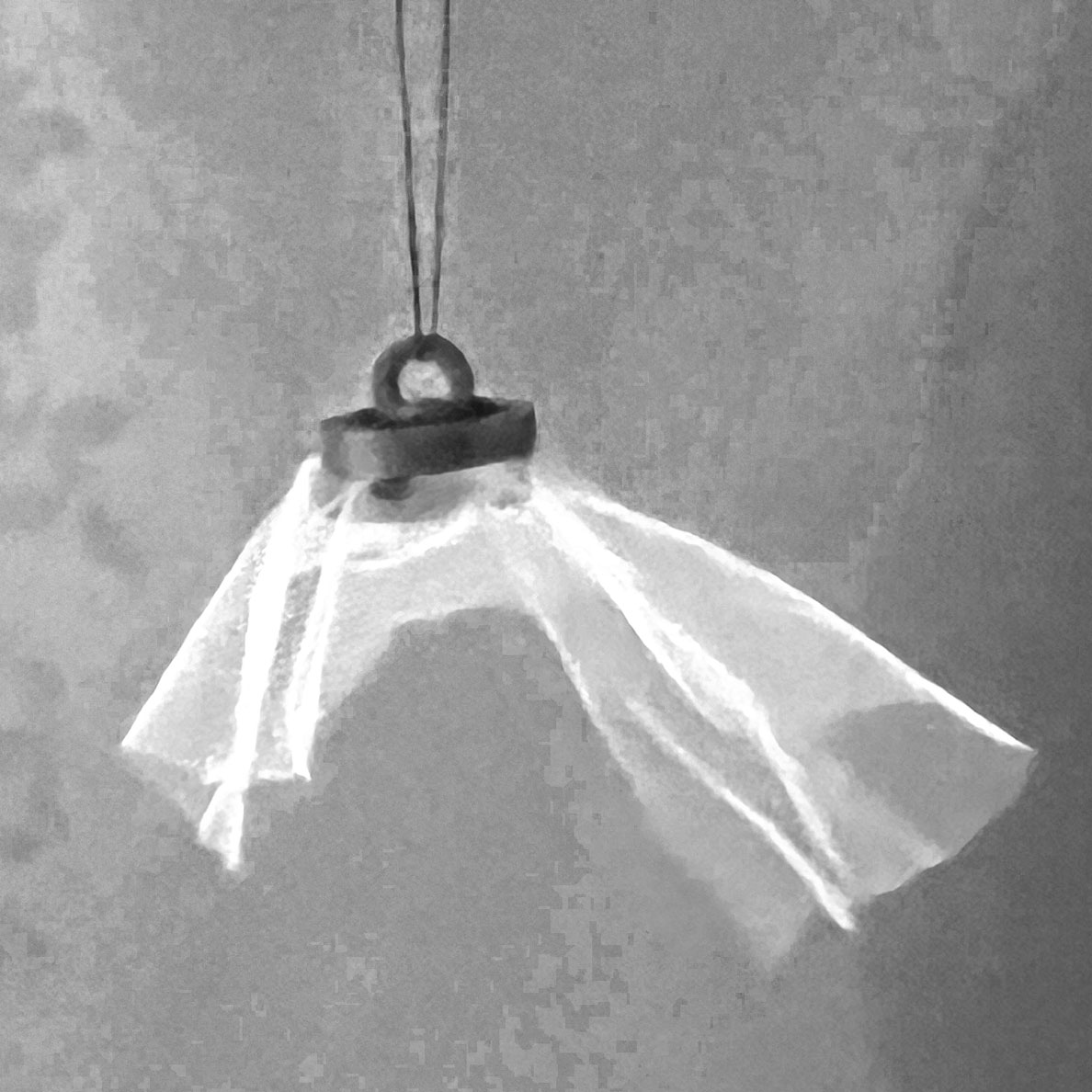
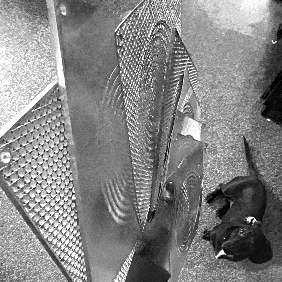
Various screen panels have different flexibilities/movements. Here are 3 exemplified in a simple pulley system.
I appreciate the changed lighting conditions of the system
And here was my little model operated by hand and ready to go for a servo.

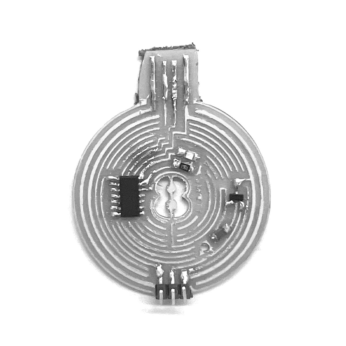
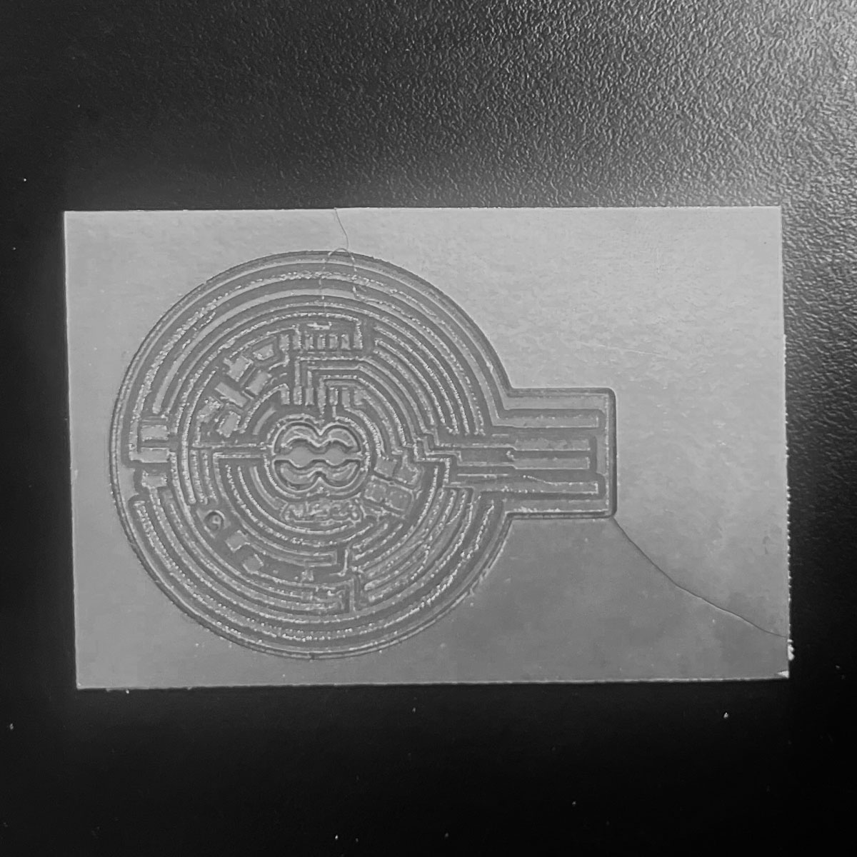
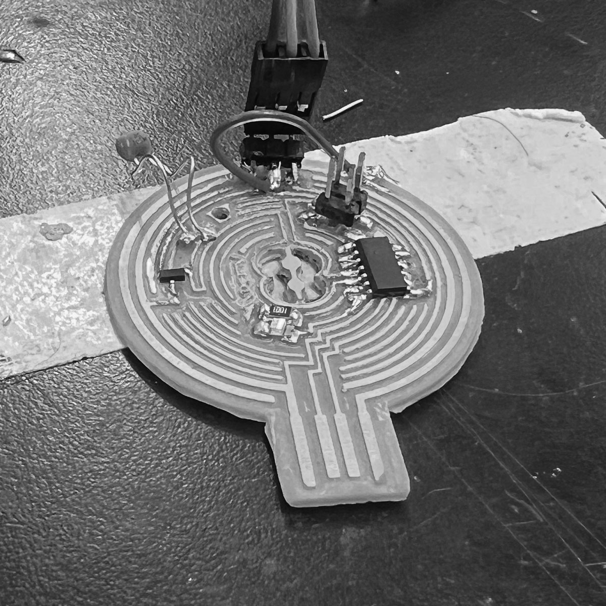
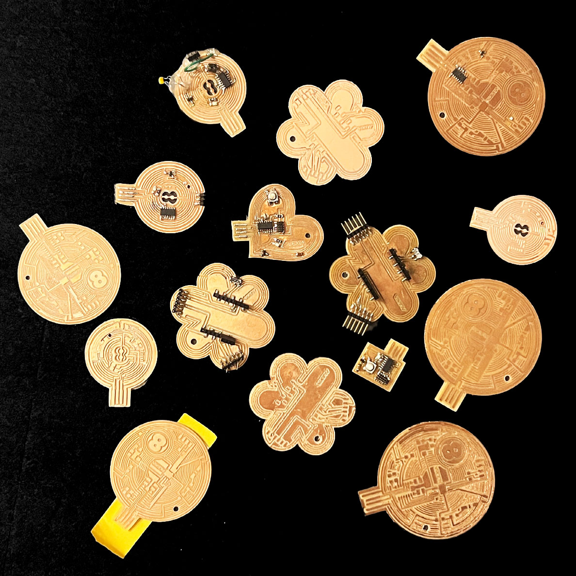
servo board traces (of course made to resemble an 8 ball because why make something unoriginal...well I'll tell you why haha)

servo board outline (another one of my hand drawn rhino designs)
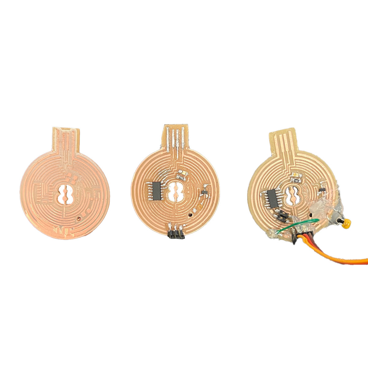
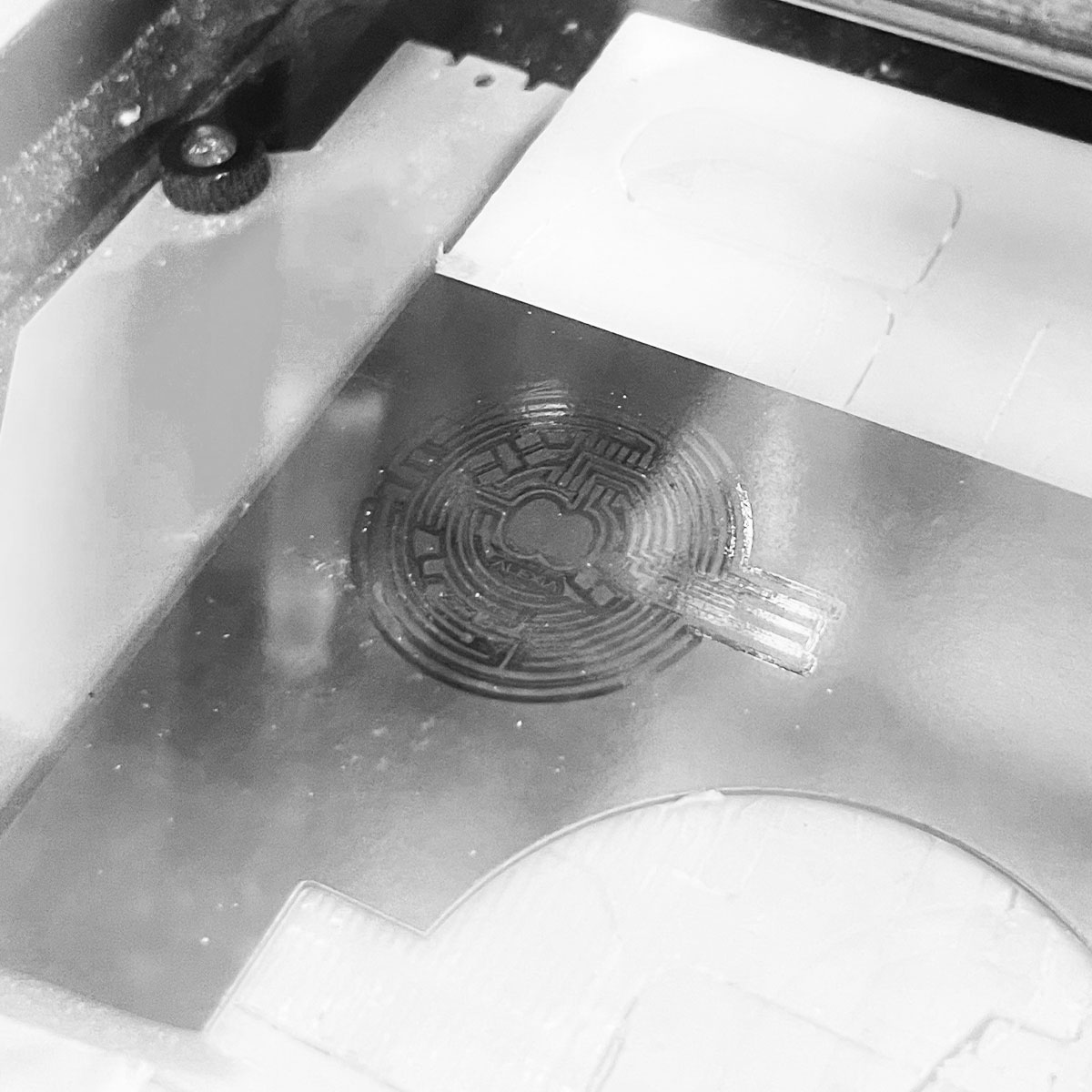
here's the story of my attempts at making my own board to run a servo:
we start off strong with a broken bit. That means there is only one bit left in the whole lab.
Next attempt was also a milling issue (at least it got closer. Maybe the board was warped. Not much to do when you are scrapping for materials. at least the second one milled well. I just needed some sandpaper to clear the copper strings between traces. Otherwise these artifacts of milling could cause shorts.
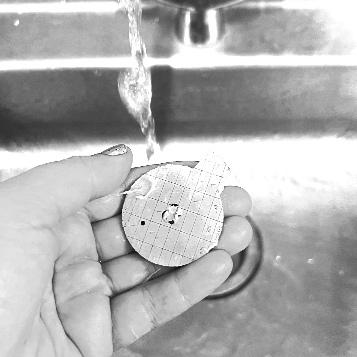
I also rinsed off the board in the sink to try to remove the stuborn leftover adhesive on the back (I find a slow pushing motion works best to take off adhesive if scraping won't work)
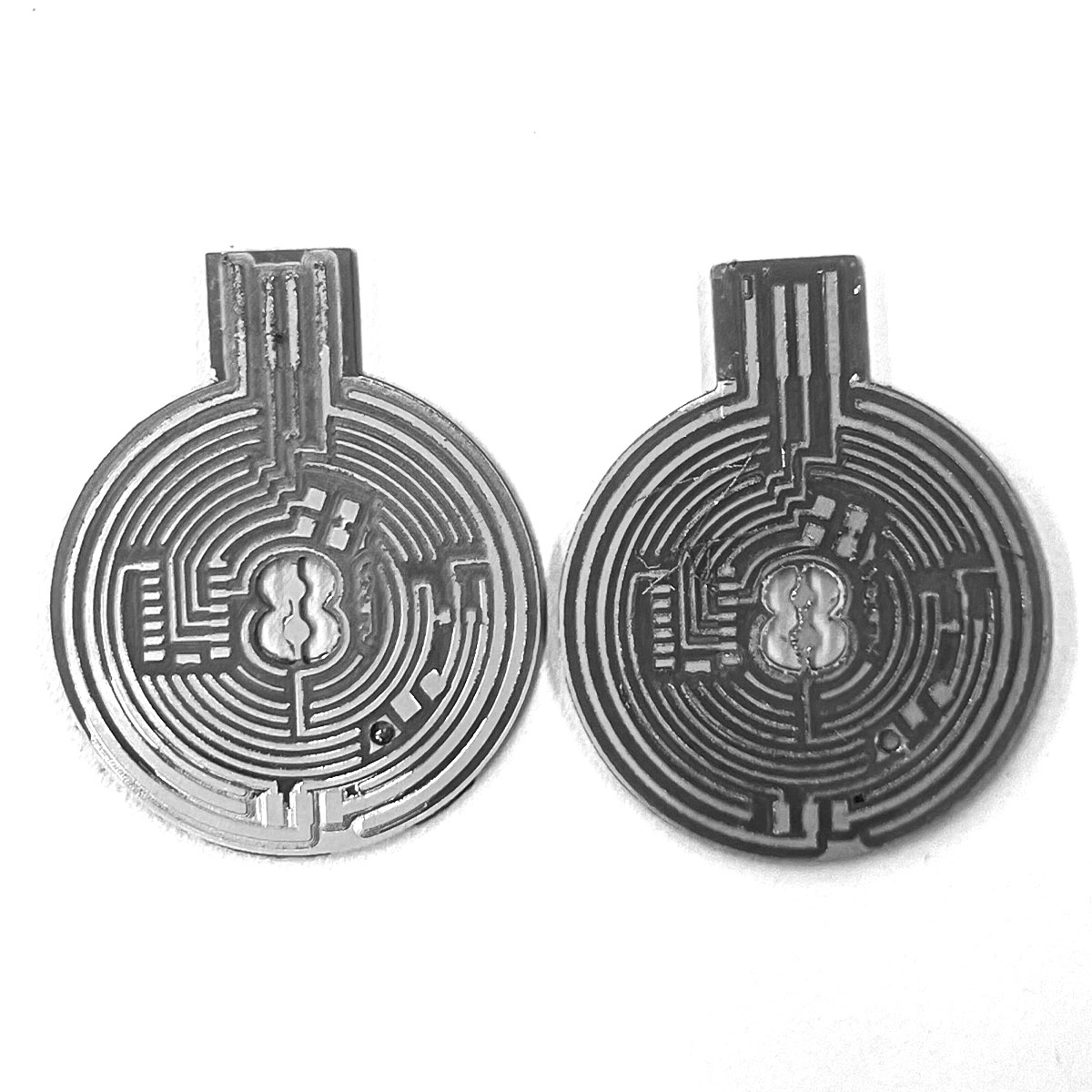
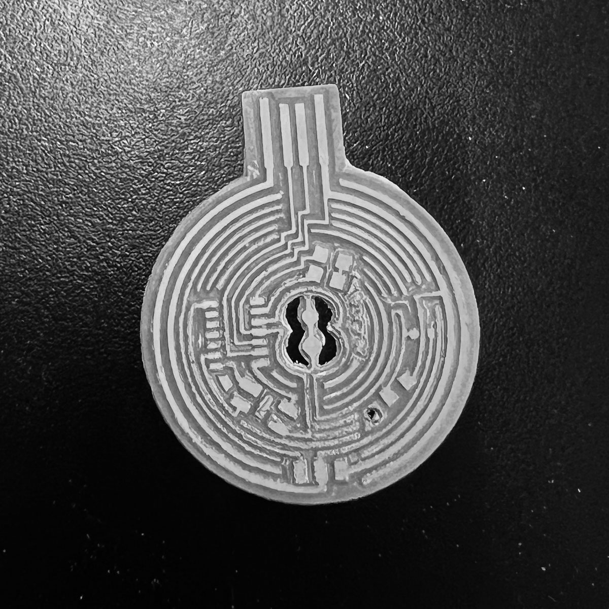
the story of this one is simple.
the process to make it went smooth...
...too smooth
Do you notice it?
NO PINOUTS FOR PROGRAMMING!
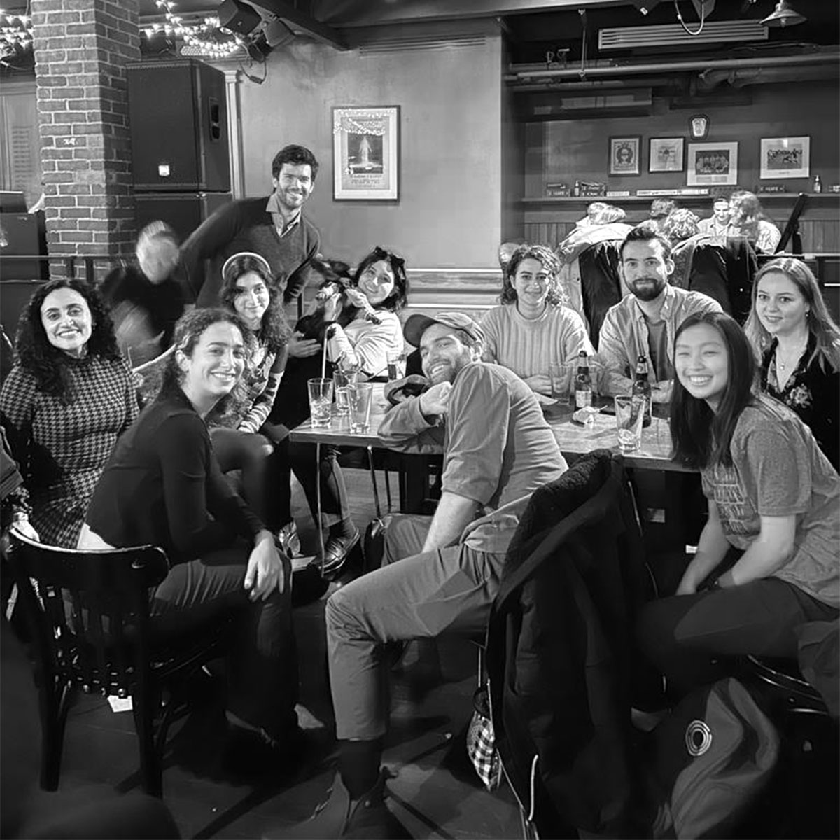

In the meantime we had a HTMAA Harvard Section group reunion at Queenshead. It really came in handy as i got in contact with Quentin to arrange to visit CBA and get all the parts I needed that we were missing in the Harvard lab
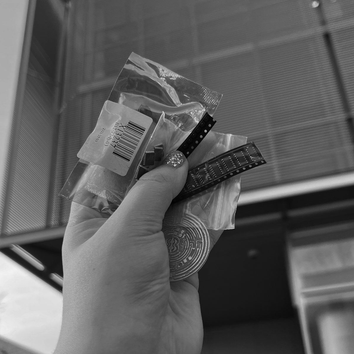
I was there at the Media Lab the next day to collect all the necessary parts. Thank you Quentin!
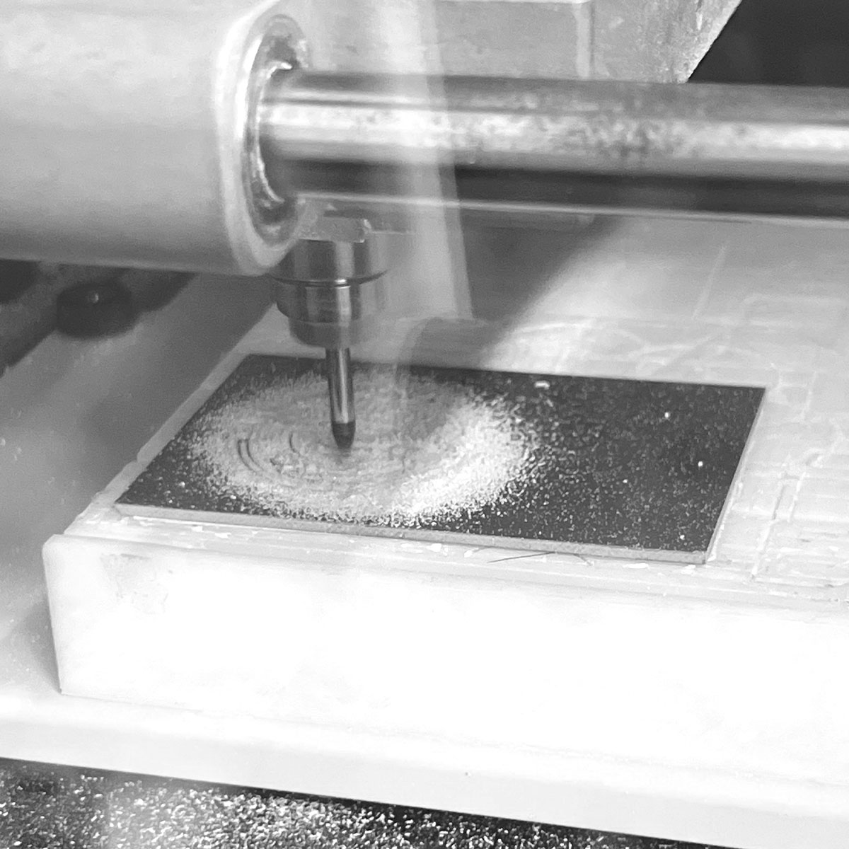
so it was back to milling
and of course something had to go wrong. I moved it before realizing it didn't cut all the way through.
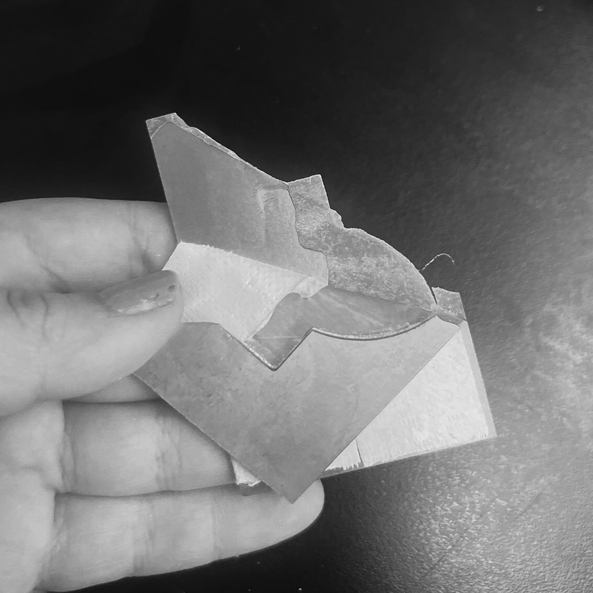
on th bright side, this made clearing copper off the back half much easier.
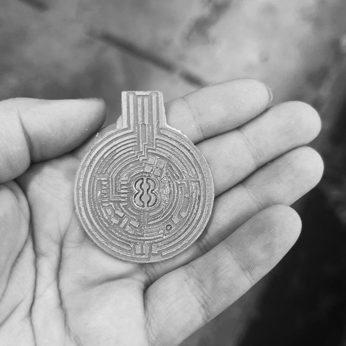
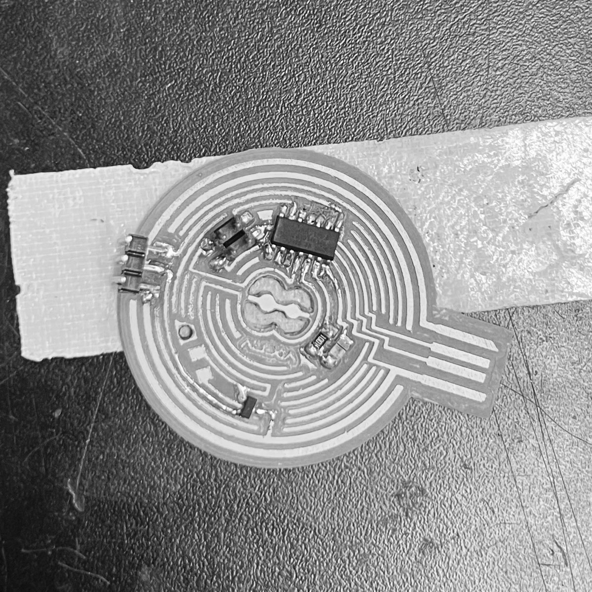
I popped it out
Then with the help of a knife and some sandpaper, I cleaned it up
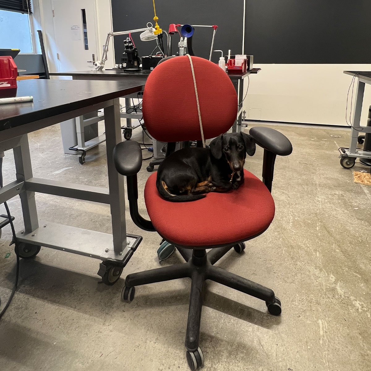
with my trusty lab partner Frankie, I was set up to solder again.
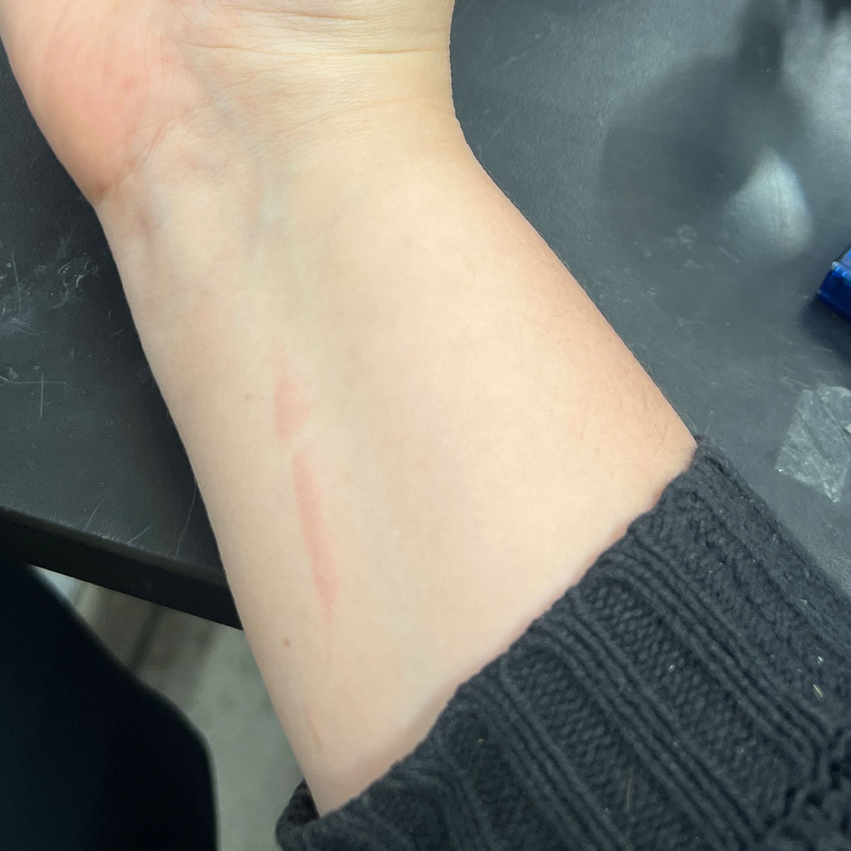
after dropping the iron on my wrist somehow
I finished soldering..almost
I needed a capacitor
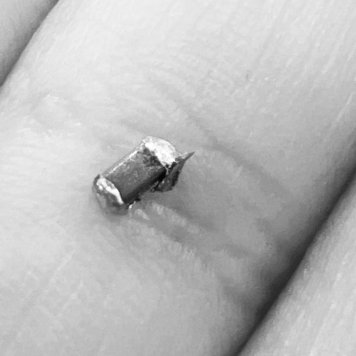
One issue.. the capacitors were no where to be found. I tried salvaging one off an old board.. and it clearly wasn't working out
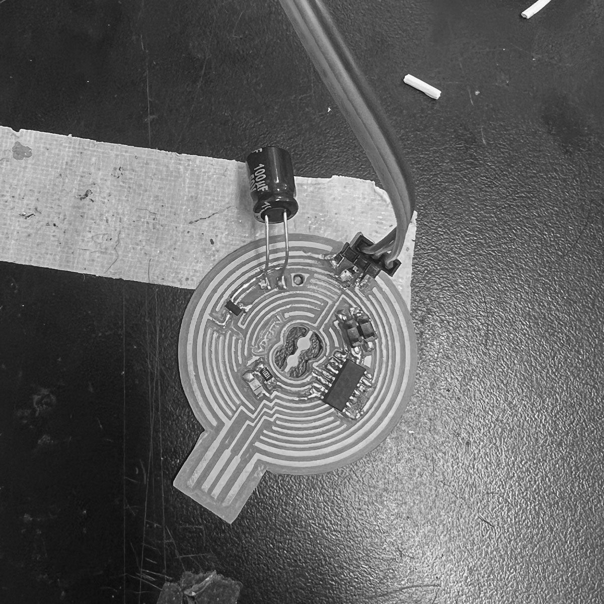
Suvin dropped by and I was so thankful. He handed me one from a breadboard. I was so excited to have a capacitor to move forward with, I soldered it on before realizing it was the wrong one.
Okay, finally got the correct capacitor (breadboard one but logically should work).
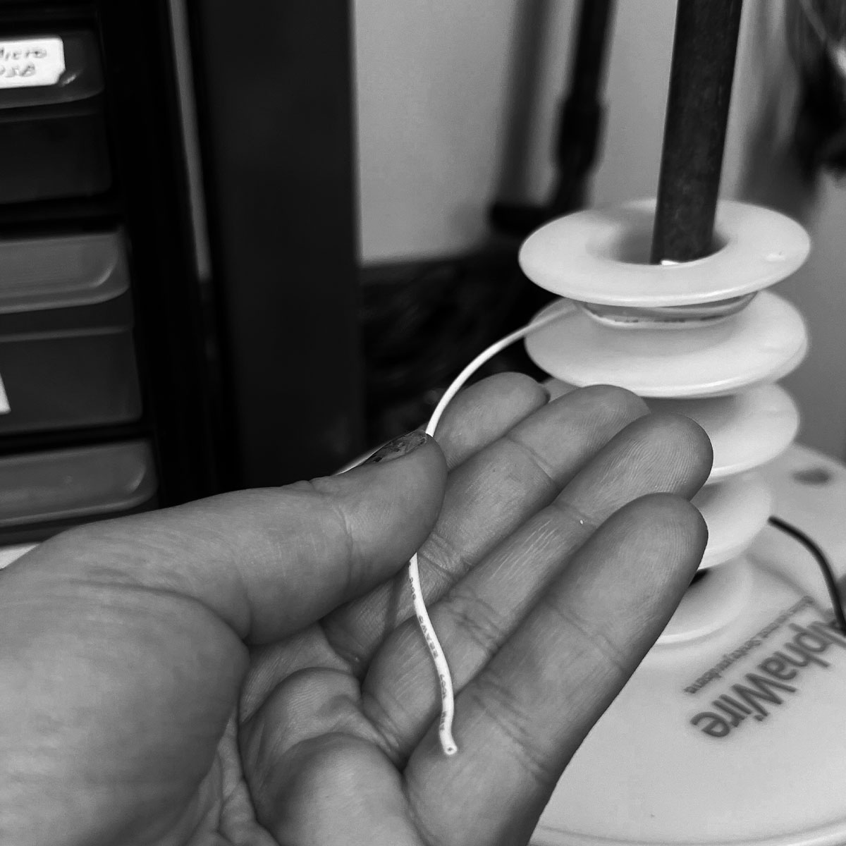
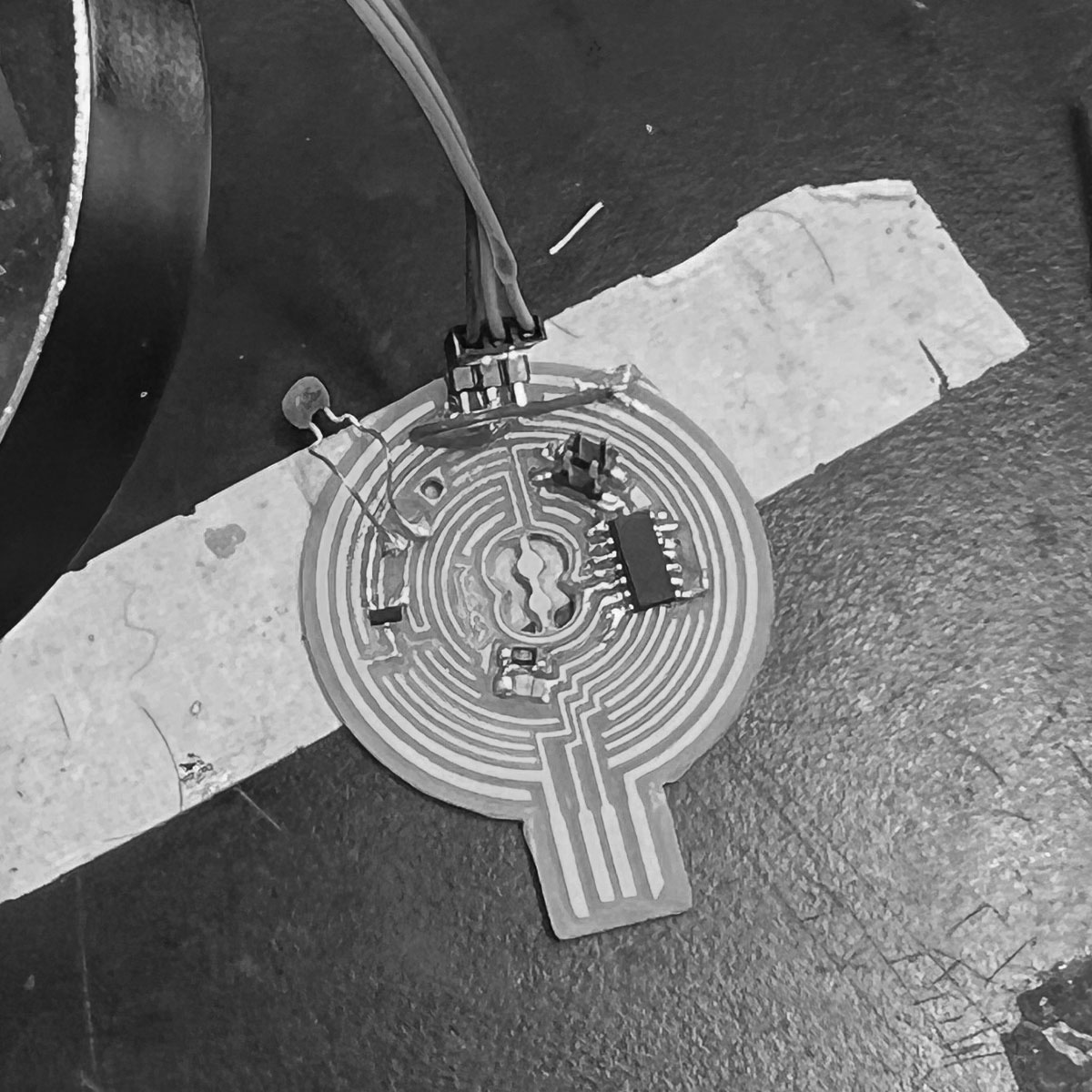
i broke a trace and needed to solder on a wire. the first wire I attempted was too rigid.
PK then advised me to cut a servo for the wire but unfortunately it was corded
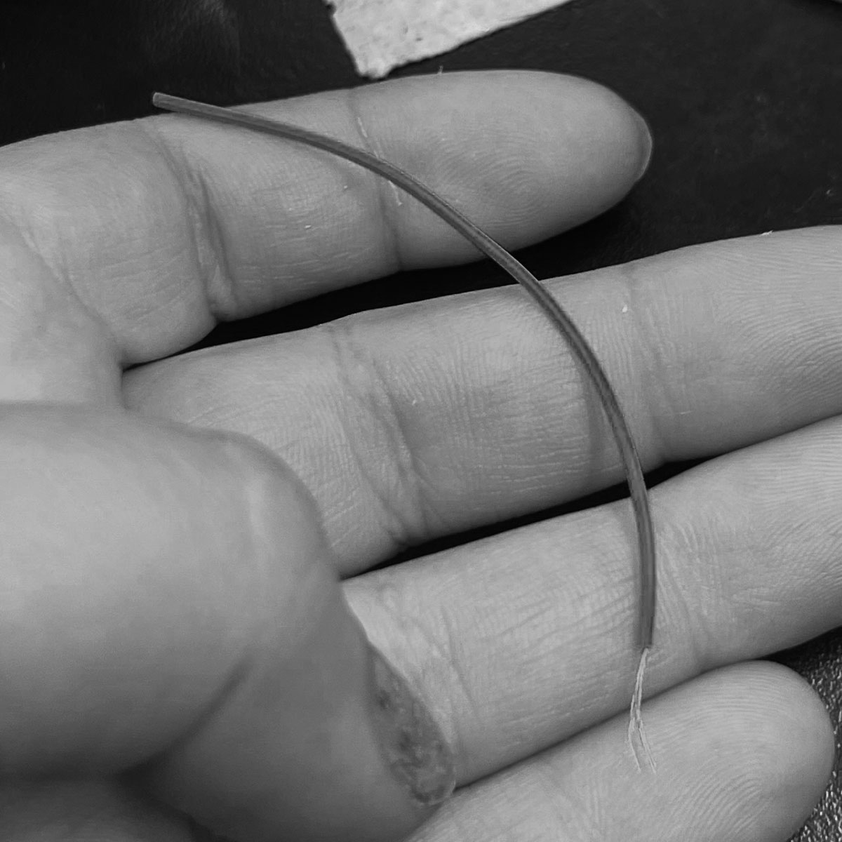
They gave me a different wire which worked out well. It was flexible so I had an easy time soldering it.
with everything soldered it was time to secure it
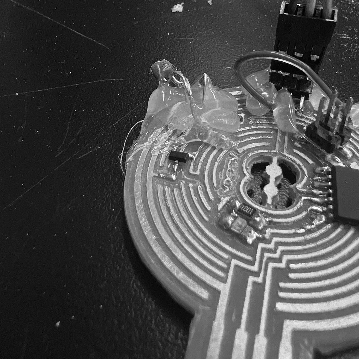
I covered everything in hot glue for safe measure
...except the processor and resistor
and that was a good thing
There was a moment were PK said they didn't understand why I kept trying and I just realized I didn't either
I would give it one last shot and then I had to move on somehow.
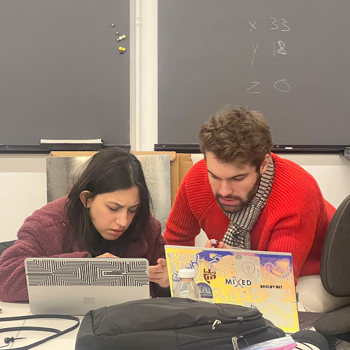
My heros came to help for this final attempt.
In trying to program we realized i put the processor on backwards. I went to fix that with a new one.
We realized my resistor wasn't outputting current. I replaced it.
I corrected all shorts or missed connections found... still not working
hard to see if there were shorts under the hot glue so i melted/scraped some away.
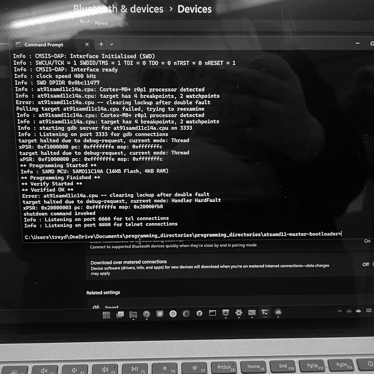
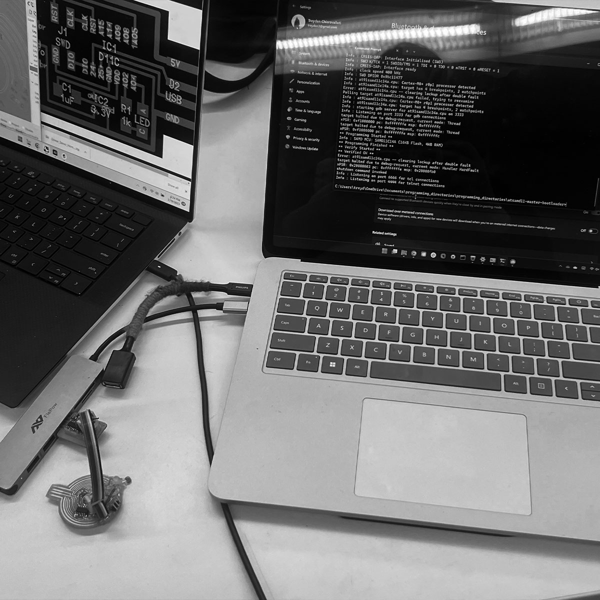
We were able to program the board (Treyden showed me a method via arduino with the new update).
But as Treyden pointed out to me, his usb hub was detecting a short in my board, neither of our computers was properly detecting my board and just because the processor pins are properly connected it doesn't mean other things are connected well.
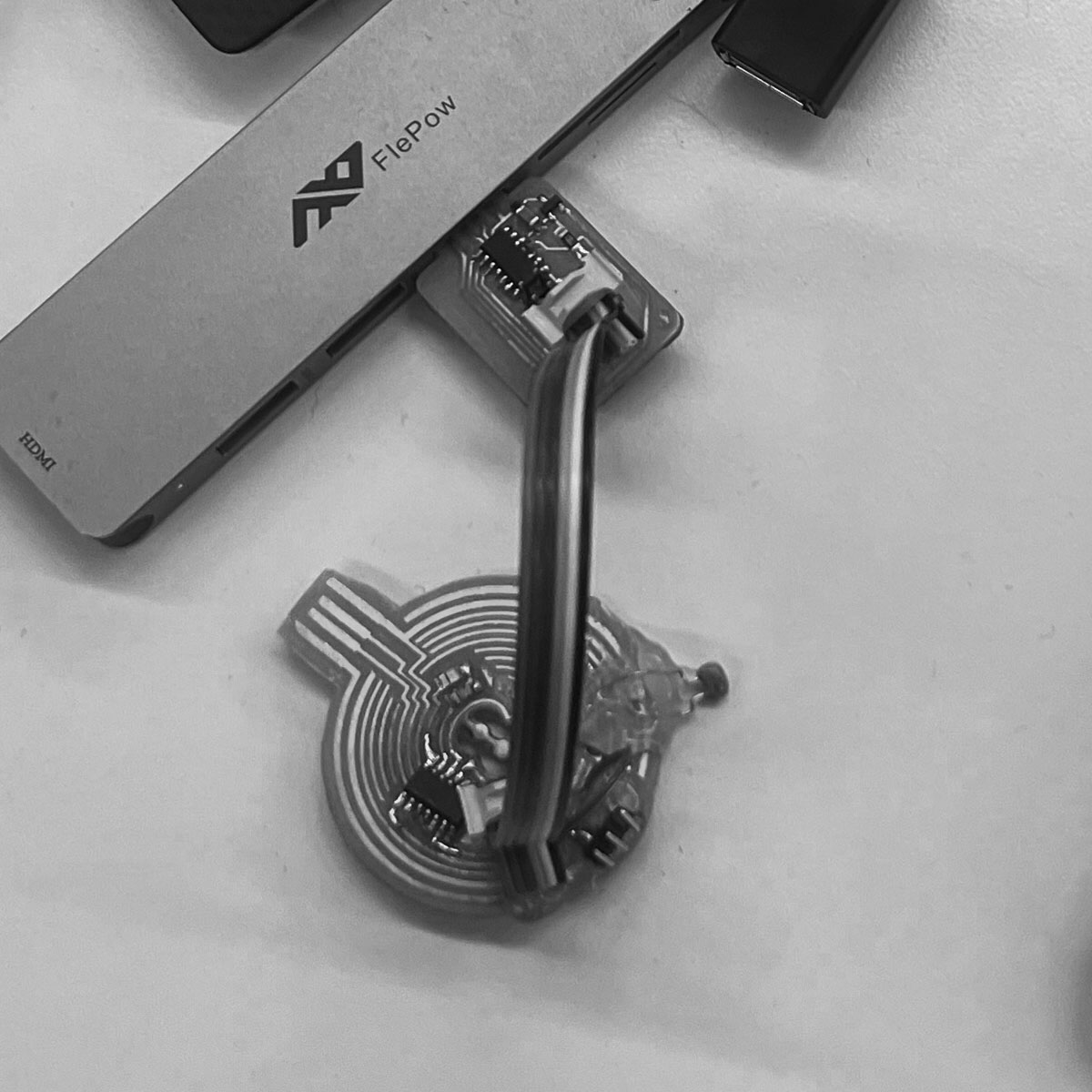
After some time of going back and forth on solutions it was late. I turned to Treyden and asked to borrow a board with pins. I just need a signal, ground, a power (what i learned from the marble machine in machine week)
I really did try so hard to make a functioning board happen, consulted with multiple TA's and electrical engineers but I think it just wasn't meant to be. At the 10th board will the 11th be different? Oh well at least I can walk away with the knowledge of what it means to design a pcb but likley use an arduino or contract someone else to do it in the future.
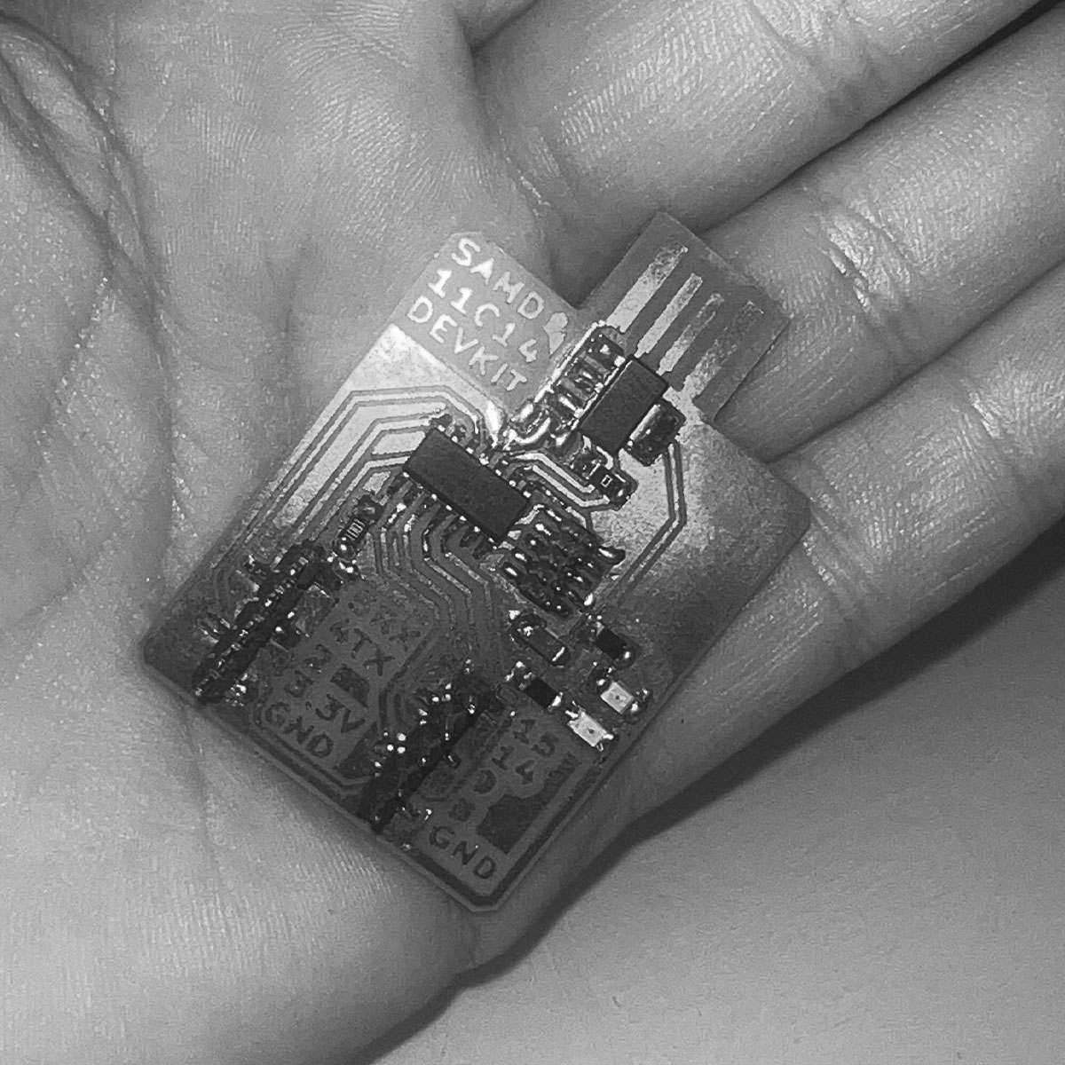
Thankfully Treyden had a board I could use.
I might have not succeeded at this one singular task of making my board function... but my project could still go on... and all it took was me realizing I needed to quit.
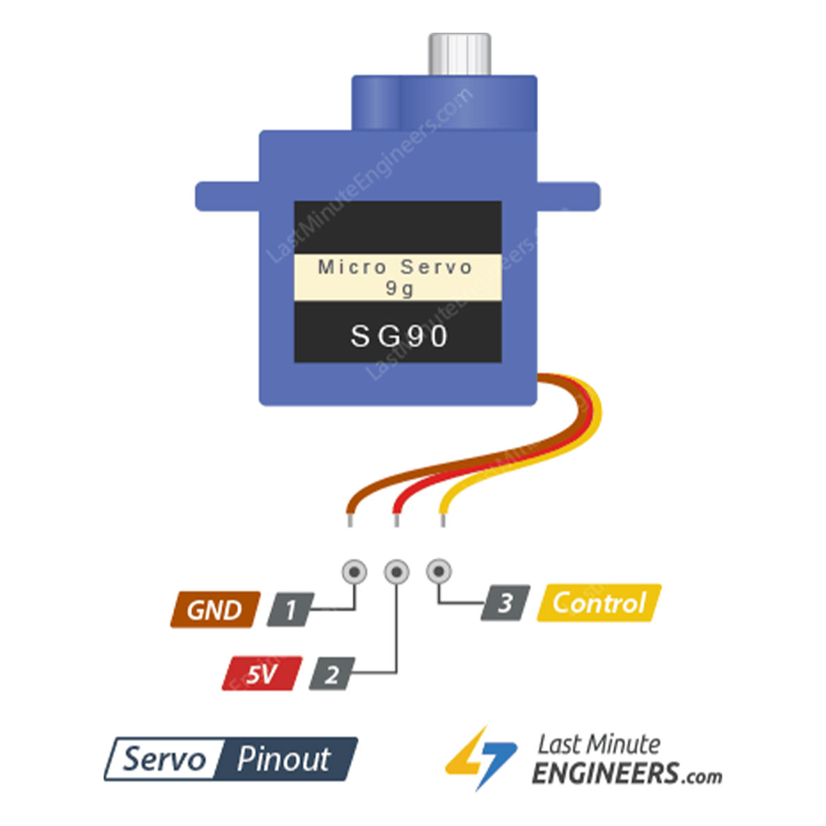
I used this pinout diagram and some additionally googled information to confirm the pins i should plug into on Treyden's board
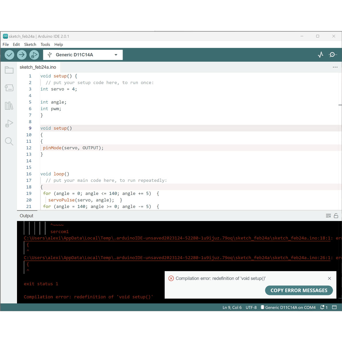
I played with a simple arduino code I got off the fab academy website but of course I couldn't get the simplest script to work...
...or so I thought.
https://fabacademy.org/2020/labs/leon/students/adrian-torres/samdino.html#servo
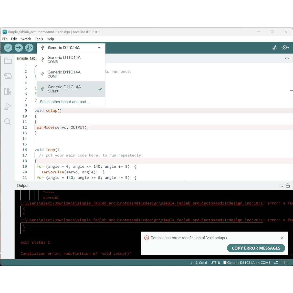
I realized none of the ports were properly showing the board (something I couldn't realize to this point because I hadn't had a successful board and for some reason all my ports said SAMD11C.
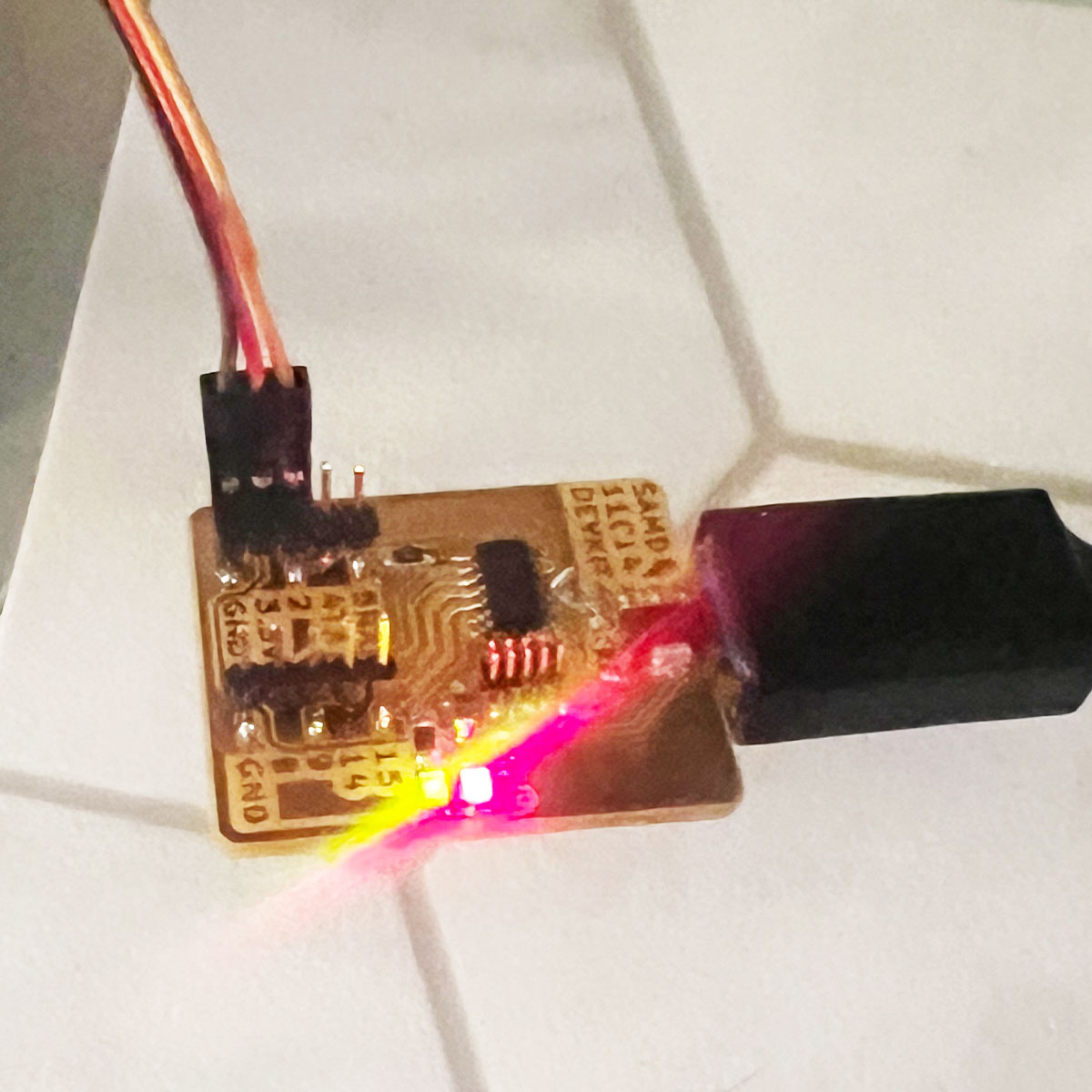
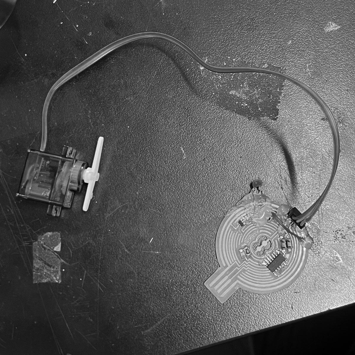
I gave it another shot switching out the usbc adapter and the board lit up!!! I plugged in the servo according to the pinout diagram.
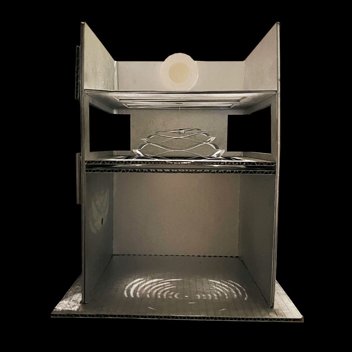
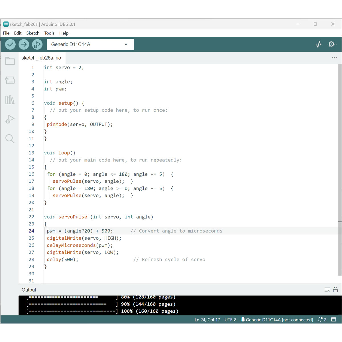
I set up the model and tested Arduino IDE.
Check my htmaa archive for the code./a>
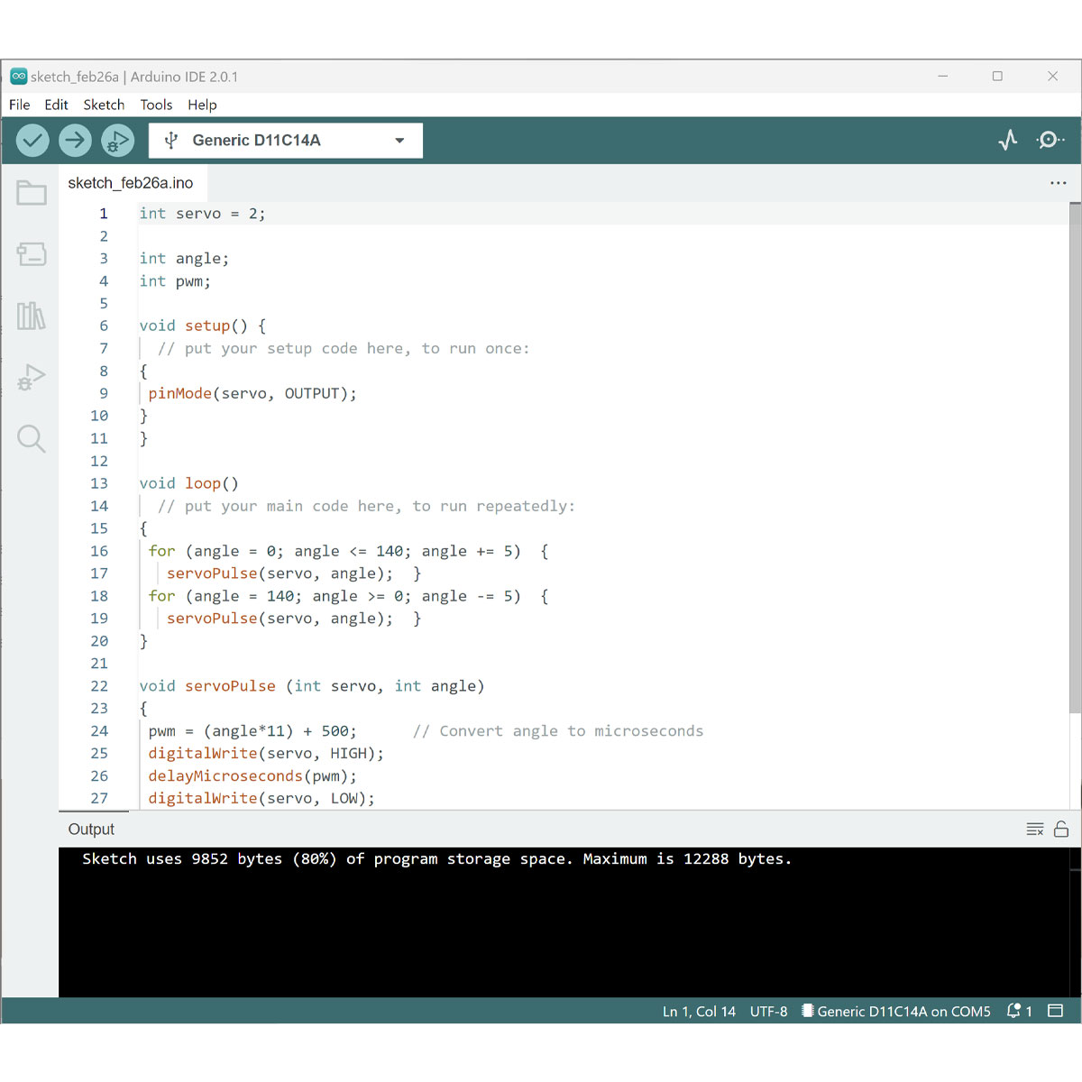
At first I had a mistake in my code that I quickly fixed.
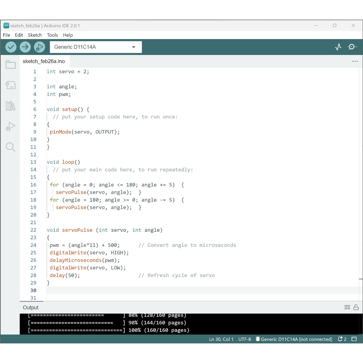
and with this bit of code the project was running!
The pulley was spinning.
I loved the sound created by the system.
The circumfrence calculations of the gear hadn't worked out in the way I hoped having the full range of motion I wished for, so if I gave it another try I'd account for some elasticity in the string and make a wider gear.
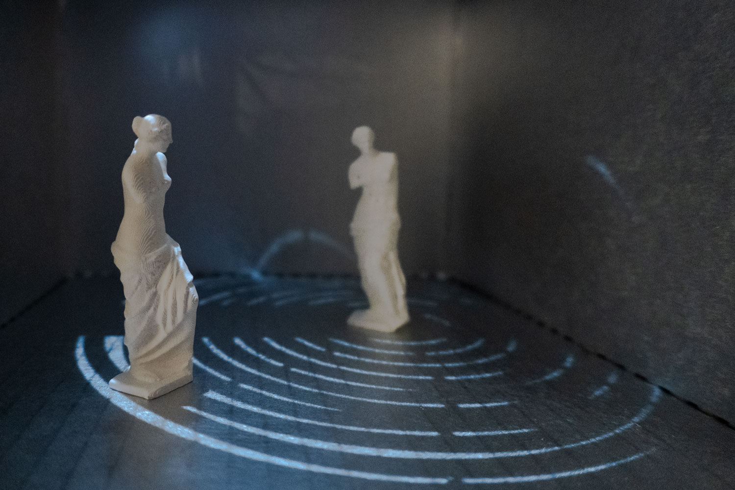
I also loved the light patterns that danced accross the floor in my project.
I played with different beats to understand timing etc.
Listen to the changed music produced by the rattling of the servo and model.
This project certainly has more room to grow and to scale but as my first delve into electronics, I have to pat myself on the back for being willing to try at least as hard as I did.
I' going to continue to work to develop my skills, but as time is a limitation me learning to give up was in essence a lesson of learning to draw a boundary for the benifit of me and everyone around me.
I am thankful at least to have experienced the skill in fragments, soldering, programming and designing my own board, even though the last steps to function had to be done on another board.
New Directions
The girl who could never design a functioning PCB no matter how hard she tried.
I always viewed quitting as a bad thing, and thought my issue was just not knowing when to ask for help, but there comes a point where help isn't enough. You just have to give up...
And I know, I know, that sounds super melodramatic of me (in character tbh) but I think despite the tears shed, the soldering burns, the nights of sleep lost, the etc. put into this project, I've learned valuable lessons.
Learning to give up came slowly but once it settled in it was a liberating feeling. You know what... maybe I'll never get another functioning pcb but I successfully 3D printed, my design was beautiful and logically should have made sense, I created unique laser cutting files and had opportunities to pass on my knowledge to others. Maybe I'll be religated to arduino Boards for the rest of my life. Maybe I'll revisit it when the timing is right. Maybe I'll just send my boards to be made out-of-house by someone with better soldering skills than me. My only regret is how much time I lost until I came to the realization that I could just move on.
While not everything is documented here, I still wanted to help illustrate my journey of deciding to move on.