Idea
This week, I built a simple programmer from scratch, starting with the
production of the PCB board, to soldering the components on, to writing a
simple program in C to upload to the programmer. While I had built lots of breadboard
Arudino circuits before, I never felt like I got the full picture. This week
drastically changed that, and the result is quite impressive. Follow me along
to see where I failed and how you can make your own!
The idea behind this simple programmer is actually from Neil Gershenfeld, who
provided the finished design for the PCB board. You can find all files for
this programmer, the USB-D11C-SWD-10, here.
In two weeks from now, we will dive into the design process and create new boards from scratch, so feel free to check out that week's post as well.
Building the PCB Board
On industrial scale, PCB boards are usually manufactured using an etching process
(for instance, lithography). However, this process requires a bunch of chemicals that
are harmful to both us and the environment. Instead, we were trained on using an endmill –
basically a mini CNC mill – that uses tiny bits to cut out the non-conducting parts from an FR1
board with a copper top. As any maker space machine, it is finicky, but procudes wonderful results
in just a few minutes and for a few cents once properly set up.
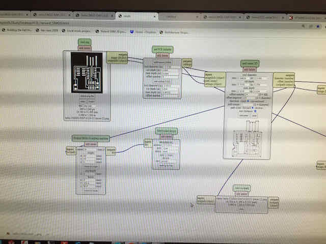
Using Mods to generate the tool path for the endmill. See the PCB board design in the top left corner
I glued the base of the FR1 board to a thick base material using double-sided tape and then adjusted the
origin of the endmill to the lower-left corner of the board. I used the thin 1/64 inch drill bit
to trace cut the non-conductive elements onto the board, leaving me with the conductive positive. It is important
to note that the drill bits are incredibly sensitive to force in the x/y plane and can easily break, so I carefully lifted the drill down so it
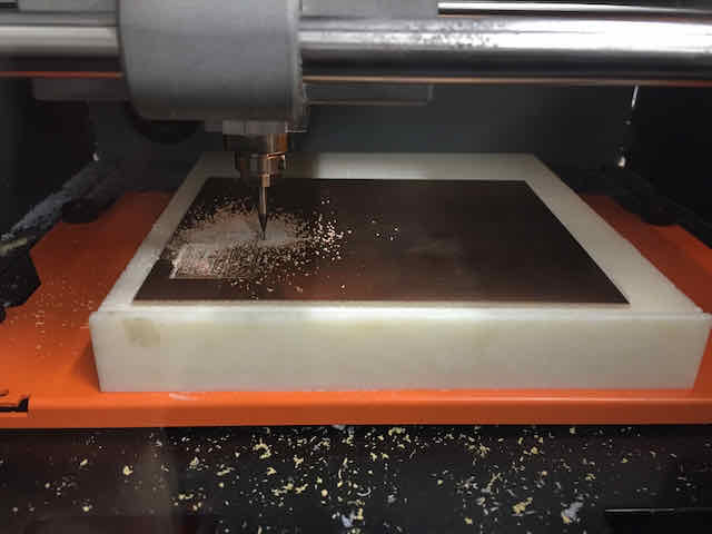
just touches the board's surface in its resting stage at z=0. Tracing the elements (run 1) went very smooth, as you can see in the video below.
After tracing the elements, I used a 1/32 inch drill bit to cut out my board from the rest of the FR1 board (run 2). Unfortunately,
during this run, the board became loose and started exerting too much pressure on the drill, so I immediately stopped the job. When I
analyzed the back of the board, I realized dust from the first job had gone under the tape and loosened its grip just where I was
cutting. The biggest learning here is to make absolutely sure the FR1 board is very securely stuck to its base – and to better be safe than sorry with the tape.
Although I had to start the entire job from scratch (as I had moved the board and resetted the mill), the drill bit was still good to use, which I quickly verified under a microscope.
As things will go wrong, standing next to the mill and being able to stop it at any time is a must to preserve bits as much as possible. Also, the cost of a bit more
tape is minimal compared to a new drill bit.

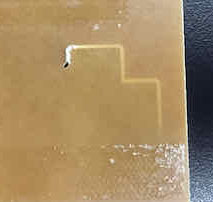
The site where the board came loose and travelled up the drill bit. Stopping the job quickly helped the drill survive this time *phew*
Dust had come under this section of the tape, loosening the board
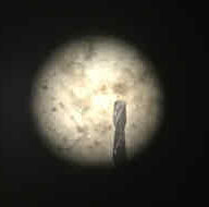
A small brightfield microscope is great to verify the drill is still good to use
In my second attempt, I used a much stronger tape and covered pretty much the entire base of the FR1 board with it, before
sticking it to the base. I also added more tape after the first run of the trace cut. This time, the board
stayed perfectly in place and the result was a beautiful PCB board! I used a metal ruler to scratch off some of the
copper that had been left in place by the endmill, and washed it in water.
Run 1: Trace cutting the non-conductive parts away

Run 2: Cutting out my board from the rest of the FR1 board
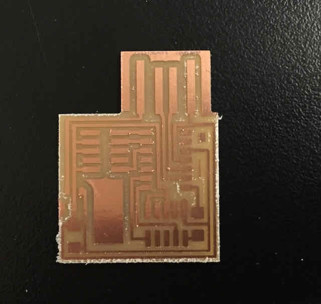
Final result
Soldering and Testing the Board
As I had never (at least properly) soldered before, this was the part I was most
excited about. I practiced for about an hour soldering broken components to old
boards, just to get an idea for the handling of it. However, this quickly got boring,
so I just started working on my board. I worked with leaded solder (which I did not like,
but given that we did not have any thin non-leaded solder, I used it) at around 775 °F. At first,
the small size of the components was very hard to work with for me, until I realized I could do
all soldering work under a microscope!
My first connections easily cost me some minutes each and I tried over and over, whereas
my last ones (the legs of the microprocessor) barely took me more than a few seconds. I was surprised it
is such a learnable skill – but maybe this goes for everything in life. A few tips and tricks I discovered
on my way that drastically helped me produce good joints reliably:
- Make sure the board connection to be soldered faces me. Turn the board as necessary
- Heat up the copper base and the leg/component to be connected a few seconds before putting the tin down. Jump back and forth between them until they are just warm enough. You can "see" when the copper is warm enough under the microscope. Then, just put tin at the very end between the iron and the copper
- Grab the tin VERY close to the soldering site with your fingers (5 cm away is totally fine). I tend to grab it too far away which makes it extremely hard to control
- Try to solder a component in a single go / quick / by just putting down solder once. The first try was usually my best and left a small and shiny connection. Reheating almost always makes the connection worse
- For legged components: Put bit of solder where one corner leg should go, use tweezers to press component down into cold solder. When ready, just place solder iron ther
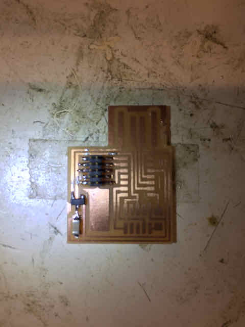
The first components, especially the capacitor and regulator were still a little shaky...

...but soon, I got more confident in my abilities and soldered the ARM chip with ease
The whole process took me about an hour and the results got better and better over time. When I was done, I could not
wait to see it in action. I immediately hooked up the USB end to my computer. Unfortunately, I could not find any signal
on the USB port and concluded something must be wrong with my board or one of the connections.
I was always very conservative about heating the components, so I assumed I had not overheated any element. Maybe one of the
connections was poorly soldered? What followed was another hour of completely unnecessary bug finding and testing every connection on the board
with a multimeter. As I later found out, it was not expected to yet show up on any USB port as it had to be
programmed by a different programmer first. At least I now knew that all connections I hade worked fine.

I wanted to go ahead and immediately push some code onto the little programmer, but it did not show up yet
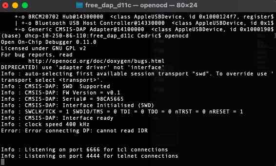
The error I got showed that my board could not be found. I later found out that I got the wiring wrong

Debugging hardware is so different from software but also very straightforward
Programming the Programmer
Finally, someone came around with a working programmer, who told me the logic behind these programmers. Basically,
he had to use his programmer to program mine into a – surprise – programmer, so I could program it. Also, I could later use
my programmer to program other's programmers...it is like a pyramid scheme. We connected my friend's programmer via USB to my
Macbook, his programmer's target pins to my programmer's SWD pins, and my programmer to an external USB power supply. With this setup,
I could use my friend's programmer to write code to my programmer. We used OpenOCD for the transfer,
which can be installed on Mac via HomeBrew. EDBG is an alternative installer that works similarly.
First, we used OpenOCD to write the bootloader to my board. This is essentially like the kernel for the AMD chip.
Second, we used OpenOCD to write FreeDAP to the chip, which is like the operating system / software environment to program the chip.
An entire documentation of the whole process can be found here. Gladly,
all connections were fine and both the bootloader and the programmer code were installed on my board. At this point, the board also shows up
as a recognized USB device in my terminal *yay*. I later used my board to transform three others' boards into programmers and spread the virus!
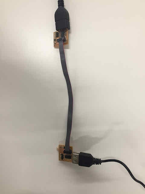
Connecting an unprogrammed to a programmed board to write the bootloader and FreeDAP
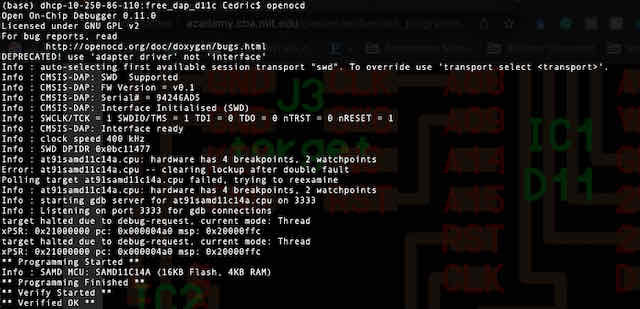
A success message for writing the bootloader to my board

After successfully writing both the bootloader and FreeDAP to my board, it is recognized as a USB device and can be programmed, for example in the Arduino IDE