Designing the Parabolic Mirror
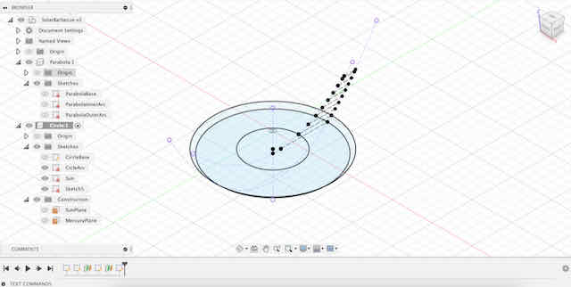
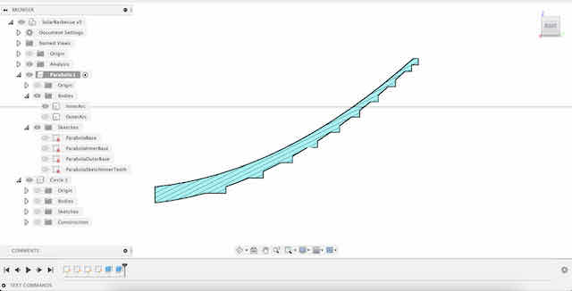
The general idea for the mirror was to create a wooden paraboloid support structure, coated with reflective aluminum sheets on the inside. I started by designing the basic layout for the parabolic mirror that would form the core of the grill. I used Fusion 360 to model my grill. Unfortunately, Fusion does not natively integrate a way to create parabolas (or other forms) from functions. In this case, I decided to instead create a rectangle in the middle of my sketch and use the top-left and top-right points as anchors for a conic curve with a rho = 0.5, forming a nice parabola. The dimensions of the rectangle defining my parabola were 100mm x 25mm, giving me a focal point at (0, 25). At this point, I trimmed down the edge of the parabola by 5 mm to place the focal point outside the mirror, since this would make it easier to design a secondary element to house the grill surface.
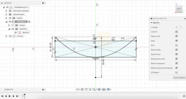
The basic parabola of my reflective element (in my case, aluminum sheets) is the starting point for my grill structure
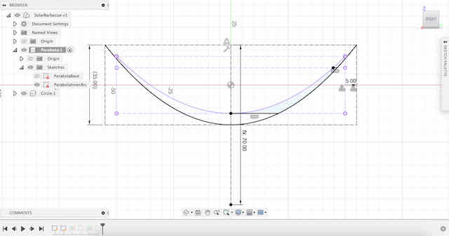
I created a second parabola that is slightly offset inwards, which will be used for the inward-facing support structures
I created a third parabola that is slightly offset outwards, which will be used for the outward-facing support structures
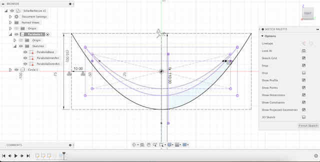
I also divided the vertical (y-axis) space between the midpoint and the end of the parabola into 8 similar-sized segments that each would house a supporting ring (one for each planet in the solar system).
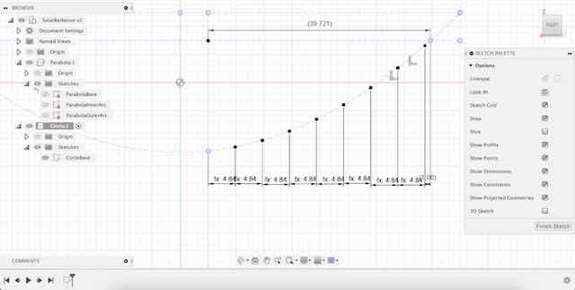
Dividing the y-axis into similar-sized segments for the supporting rings

Each ring's width is the space between the inner and outer parabola
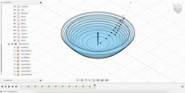
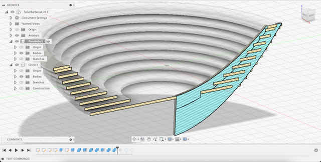
Revolving the circle elements around the center axis creates the circle support structures we want
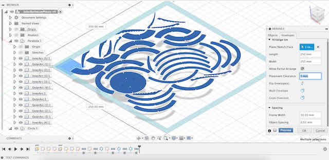
Our final sketches. Time to extrude them
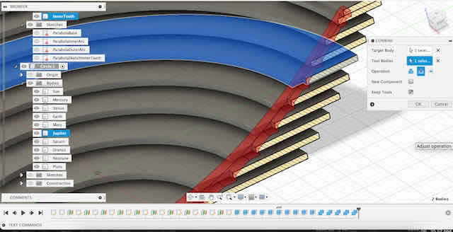
I continued by extruding the relevant profiles of the 8 planet rings, as well as the inside and outside ribs that would later hold everything in place. The most challenging part of the design came next, which was about designing the press-fit system that locked the 8 planet rings to the 6 inside and 6 outside ribs. At first, it was quite hard for me to picture this fit in my head, until I realized that the system is actually quite simple: the length of the incision on the outside part determines how far it goes into material. To make modelling easier, I chose to only model the incisions I wanted to create in the ribs – and then later cut the planet rings with these incisions. In retrospect, this made the entire design dependent on the 3D arrangement of the components rather than their parameters, which was harder to work with. I should have just modelled the appropriate incisions for the press-fit into the circle sketches defining the rings. This whole design is quite hard to describe in words, so I hope the pictures below help you understand the process better.
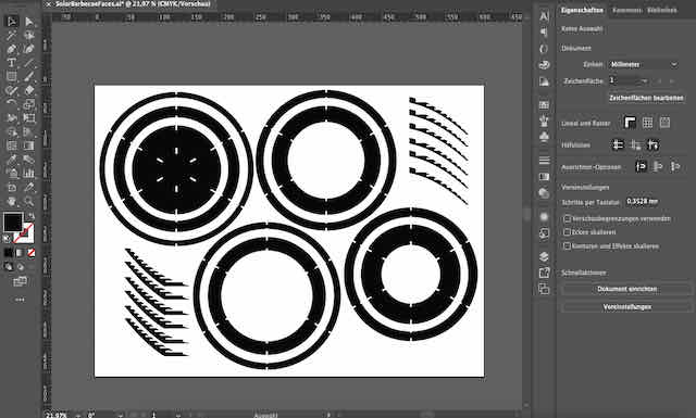
This is the final output we want to get to – 8 circles and some inner and outer support ribs that hold the circles in place. The inside radii (cool word, right?) of the 8 cirles follow exactly our primary parabola, so their focus is in our original focus point

We start with the inner ribs and divide them into two sections (see the black line that divides the blue rib into two pieces)
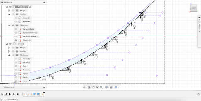
For the "more inner" of the two parts of the inner rib, we create little perpendicular teeth along the parabola
This is what the inner part of the two inner ribs looks like with this design
Next, we cut each of the 8 planet rings with the inner part of the inner rib, to create fitting incisions
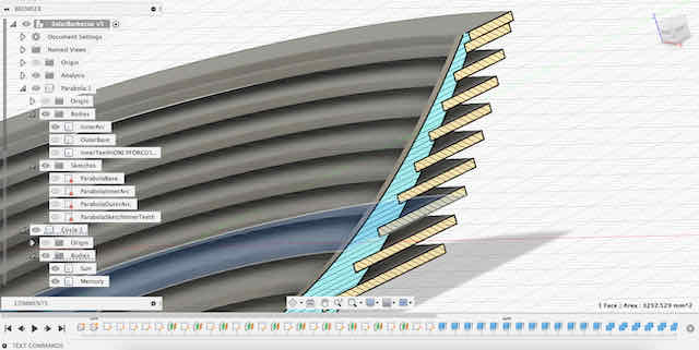
We combine the inner and the outer part of the inner ribs, so that we retain both the teeth/cutouts at the planet rings, but also some more surrounding support material all the way to where the outer ribs start
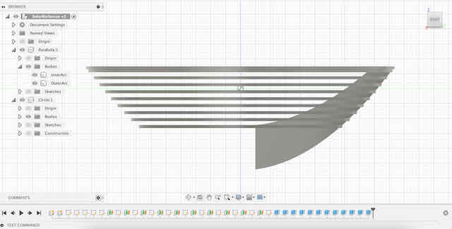
Last, we repeat the same for the outer ribs and thus create our final supporting ribs
I also realized very late in my design that although my design was parametric, it was extremely hard to impossible to change dimensions and have them propagate upwards. The biggest problem came from the constraints created to define the conic curve, which also had several attaching constraints set onto it. Due to this, whenever I tried adjusting the dimensions of the rectangle defining the conic curve, I got an error that the attaching constraints were still applied. This made my prototyping extremely slow and very inflexible. Unfortuntely, this problem only became apparent to me when I did try to update the dimensions of the base parabola to reflect the dimensions of the material we were given. In future, I should make sure to have appropriate sizing from the start, and avoid circular dependencies created on conic curves (although, I think, in this example, it is a design flaw in Fusion).

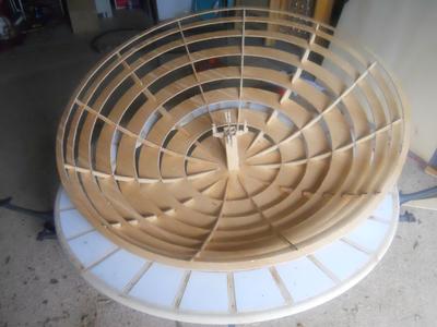
The final shape with 8 planetary rings and 6 supporting inner and outer rings