
Quidditch (the sport) has become a major part of my life in the past year. The sport is young and always open to improvements. I would like to develop a quidditch goal-scoring detection system. As of right now, a goal is determined by a single person standing behind the hoops and squinting to see if a shot passed through. There is currently no technology implemented to help with this, and so goals are often falsely ruled or contested. I would like to eliminate this uncertainty. I plan to construct a hoop that can detect when the quaffle (volleyball) passes through, and distinguish this from the keeper's hand, which is also allowed to pass through the hoop. The output is a string of LED lights that lights up to indicate a goal. In the future, one could implement some kind of remote screen visible to the head referee and add speed detection or other fancy measurements.
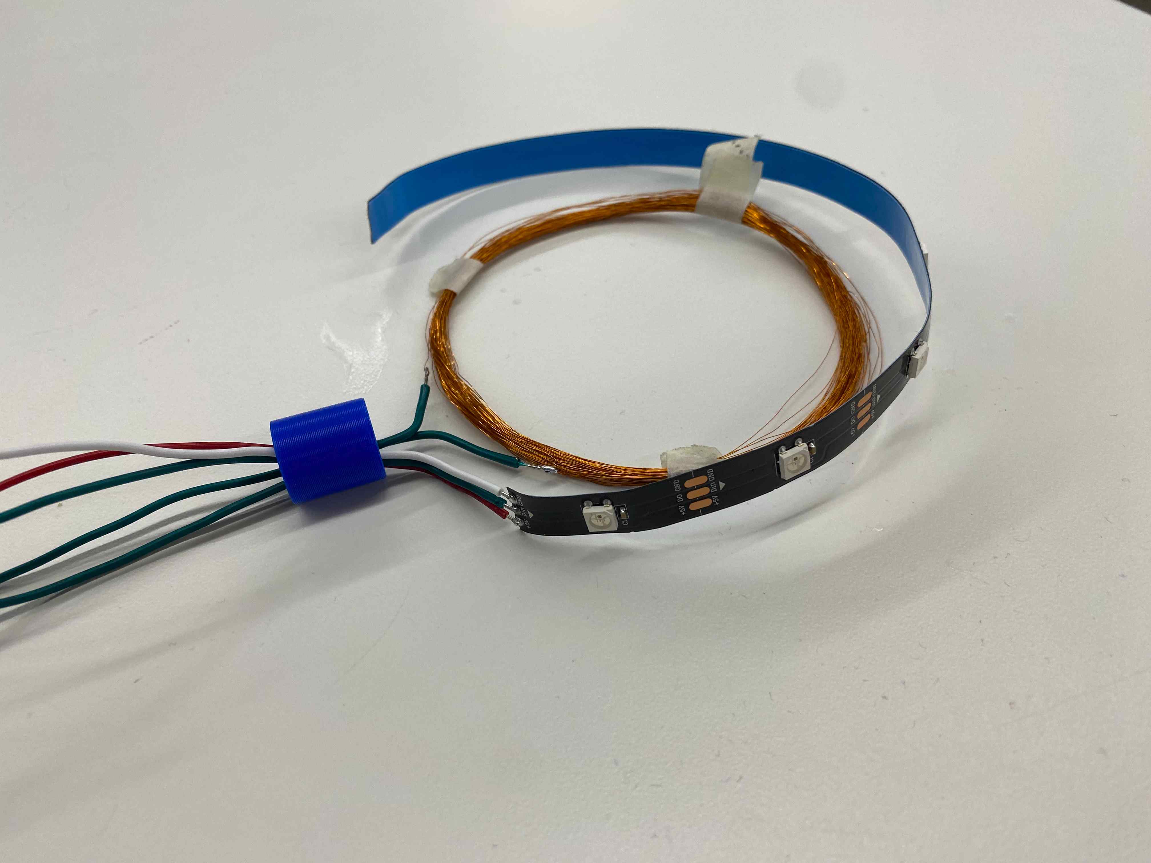
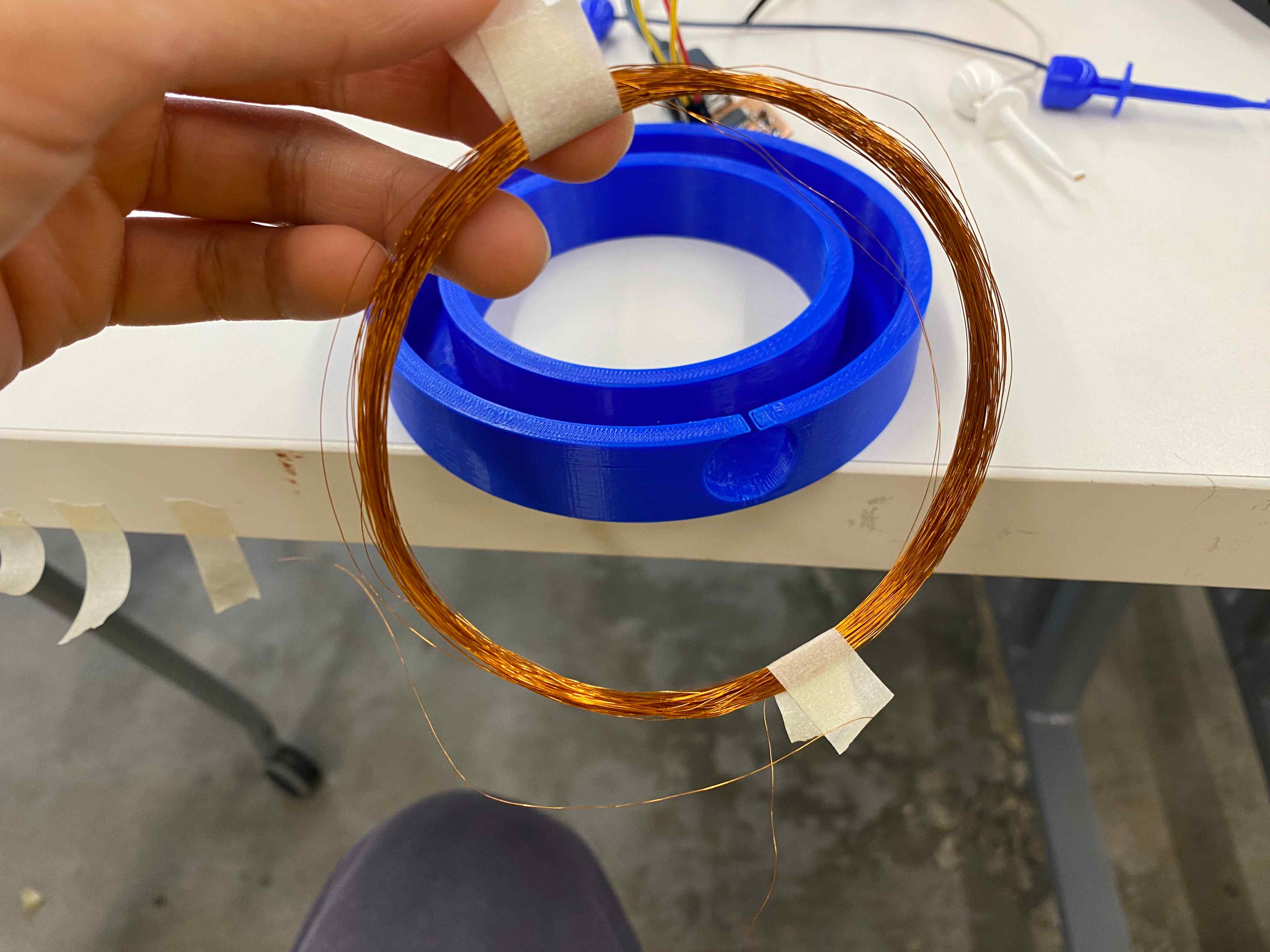
Design a ring of the desired hoop size and 3D print. Wrap the magnet wire about 100 times around the ring's circumference. Sand the wire ends so that they are exposed, then connect a multimeter to test it. There should be low resistance (not exactly 0 because the coil is so long). When the magnet is dropped through the coil, a small change in voltage should be seen. Cut an LED strip of the same circumference. Solder wires as necessary and feed them through a 3D printed "neck" piece.
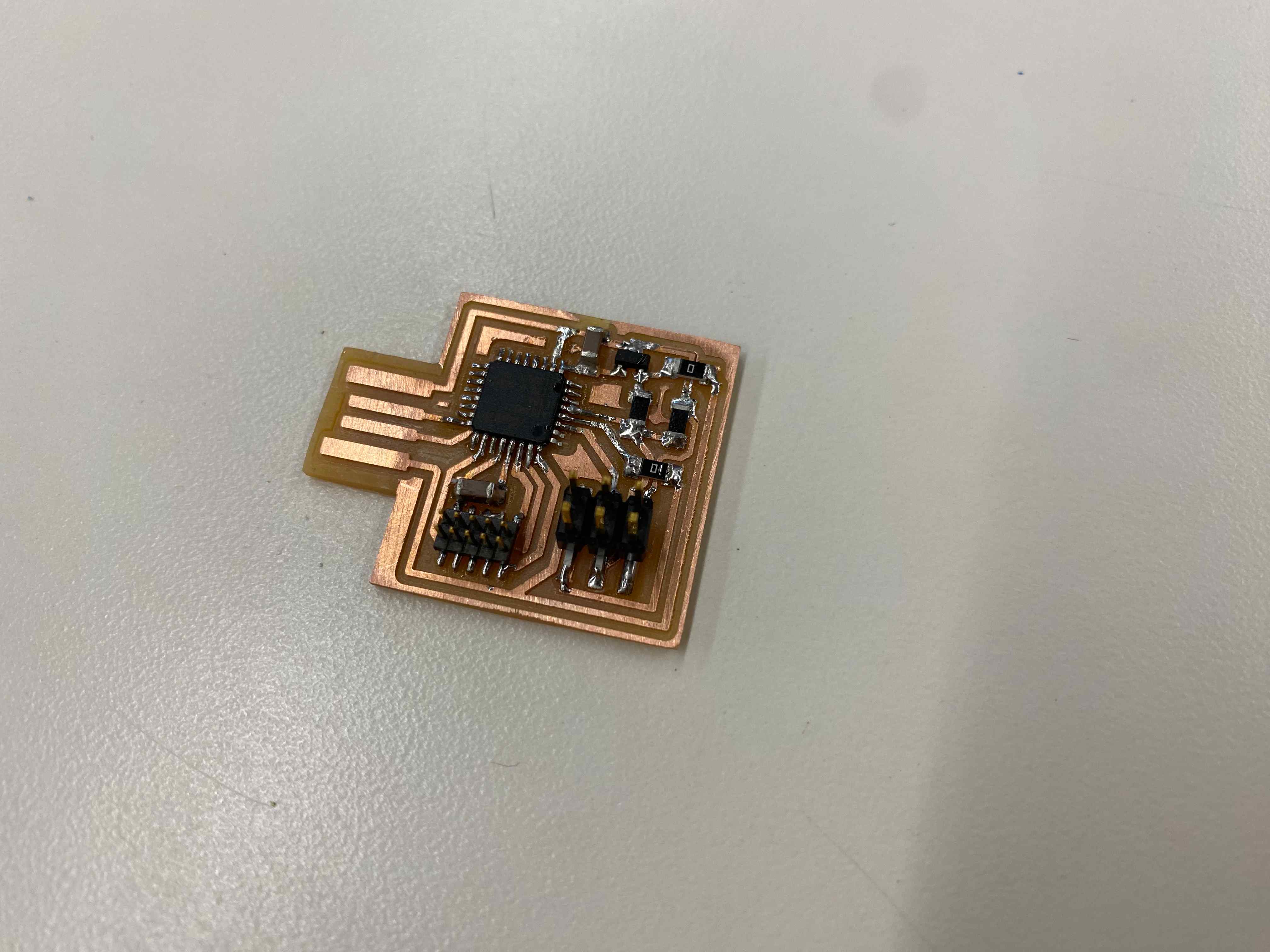
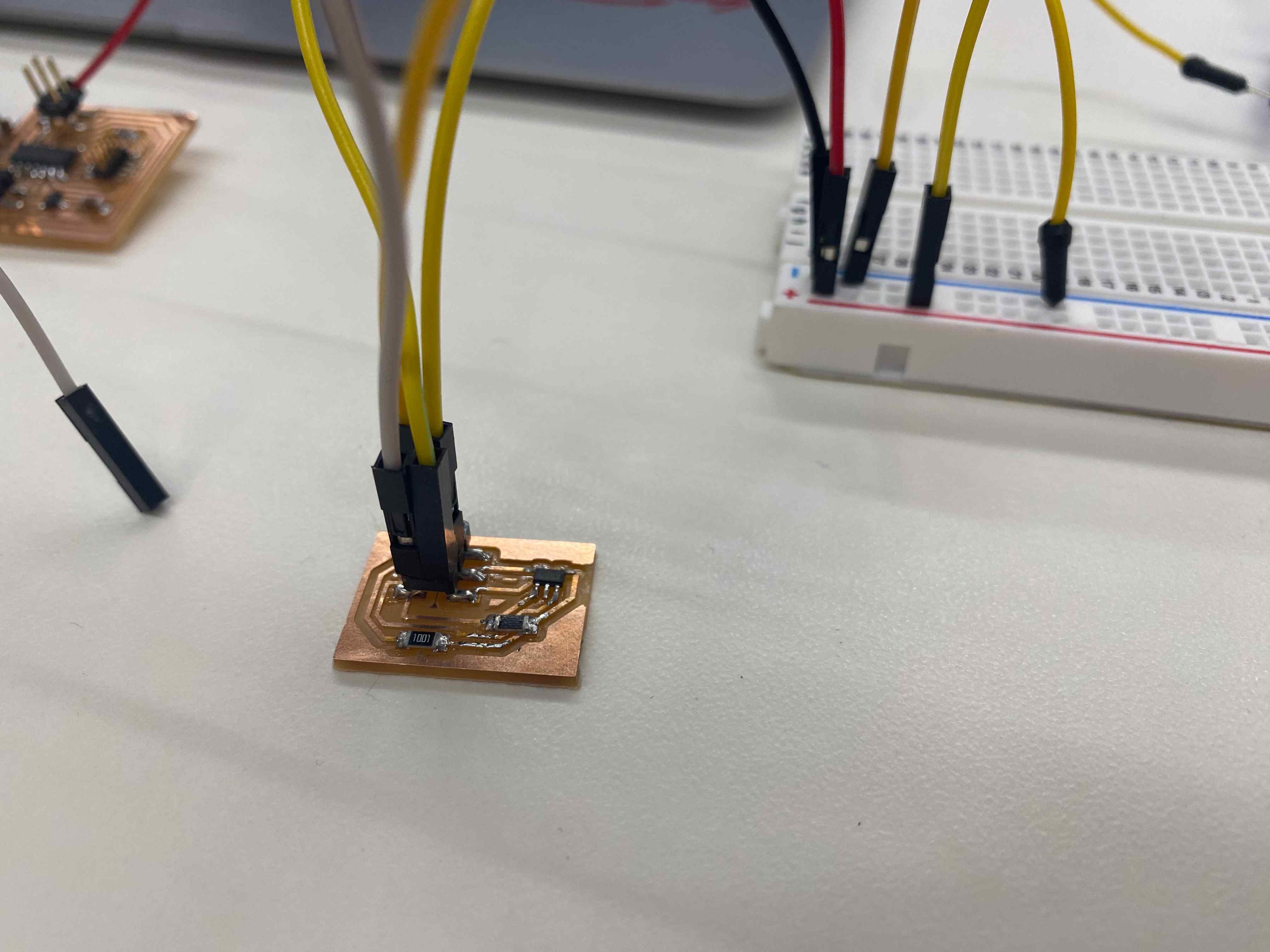
Design a board using three data pins: one for Tx, one for Rx, and one for signal to LED strip. Implement the step response schematic, as seen on Rob Hart's website . Mill and stuff the board.

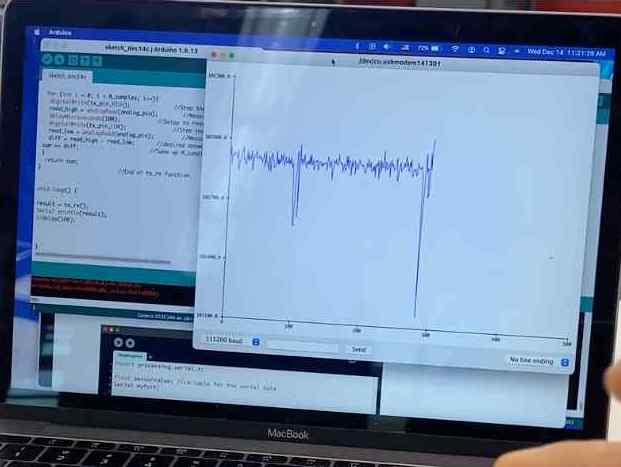
Program the board. Use NeoPixel to control the LED strip. Write code to implement step response and, when a certain threshold of deviation from the mean is registered, turn on LEDs temporarily, then turn off.

Keep a variable for goals scored and print this to serial. Create a web serial interface folder and write html, js, css files to read the goal count and display it.


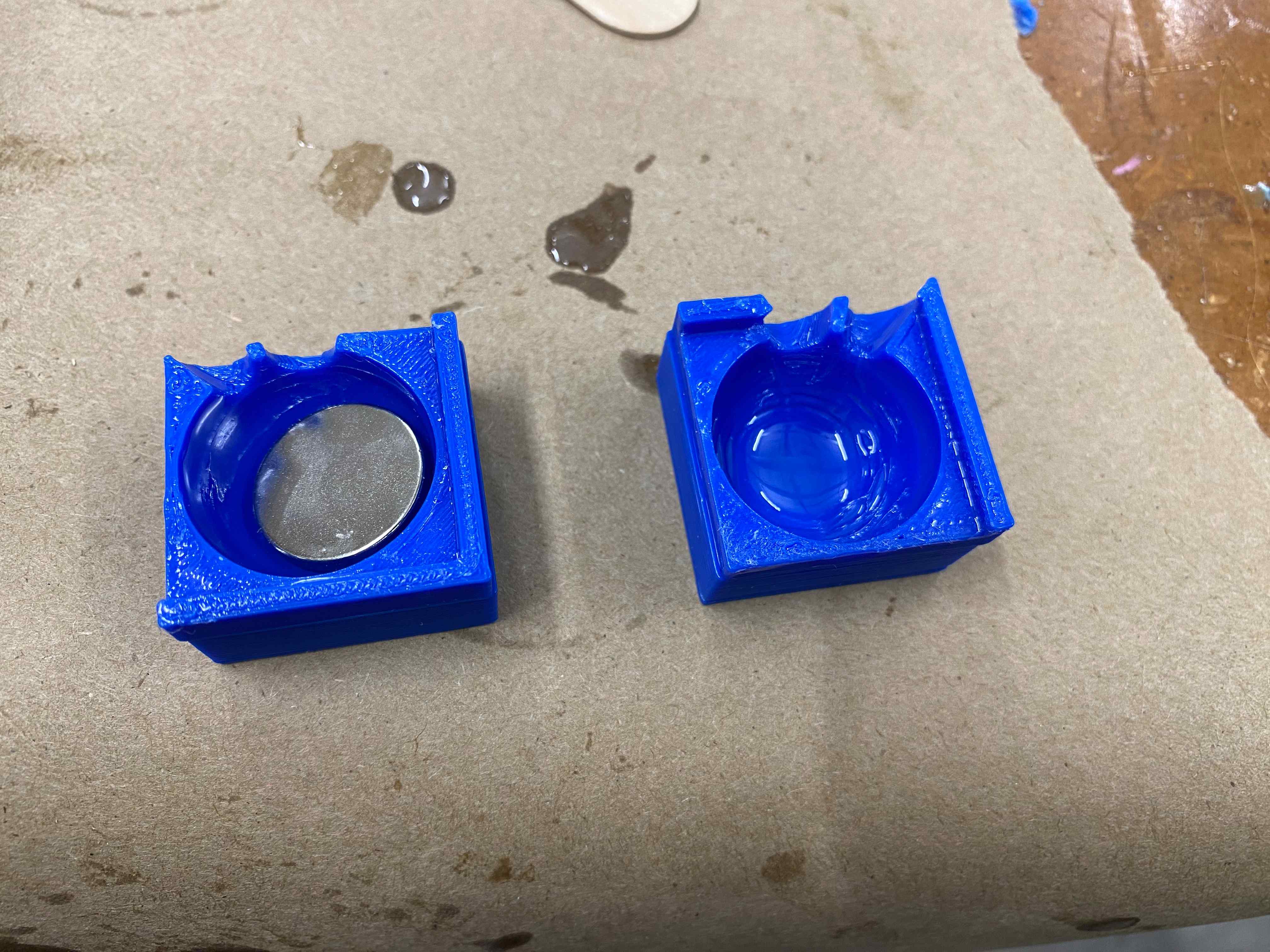
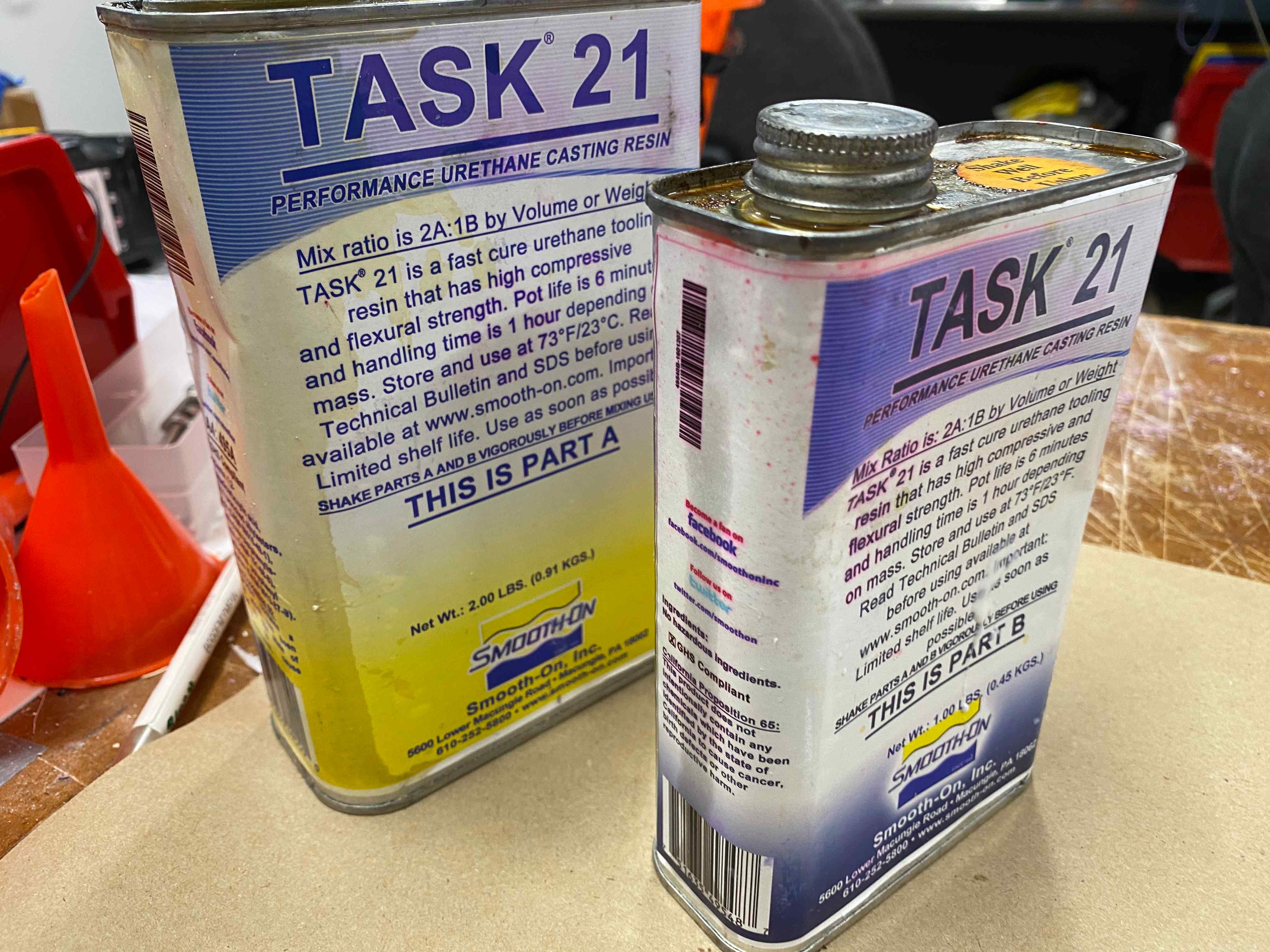
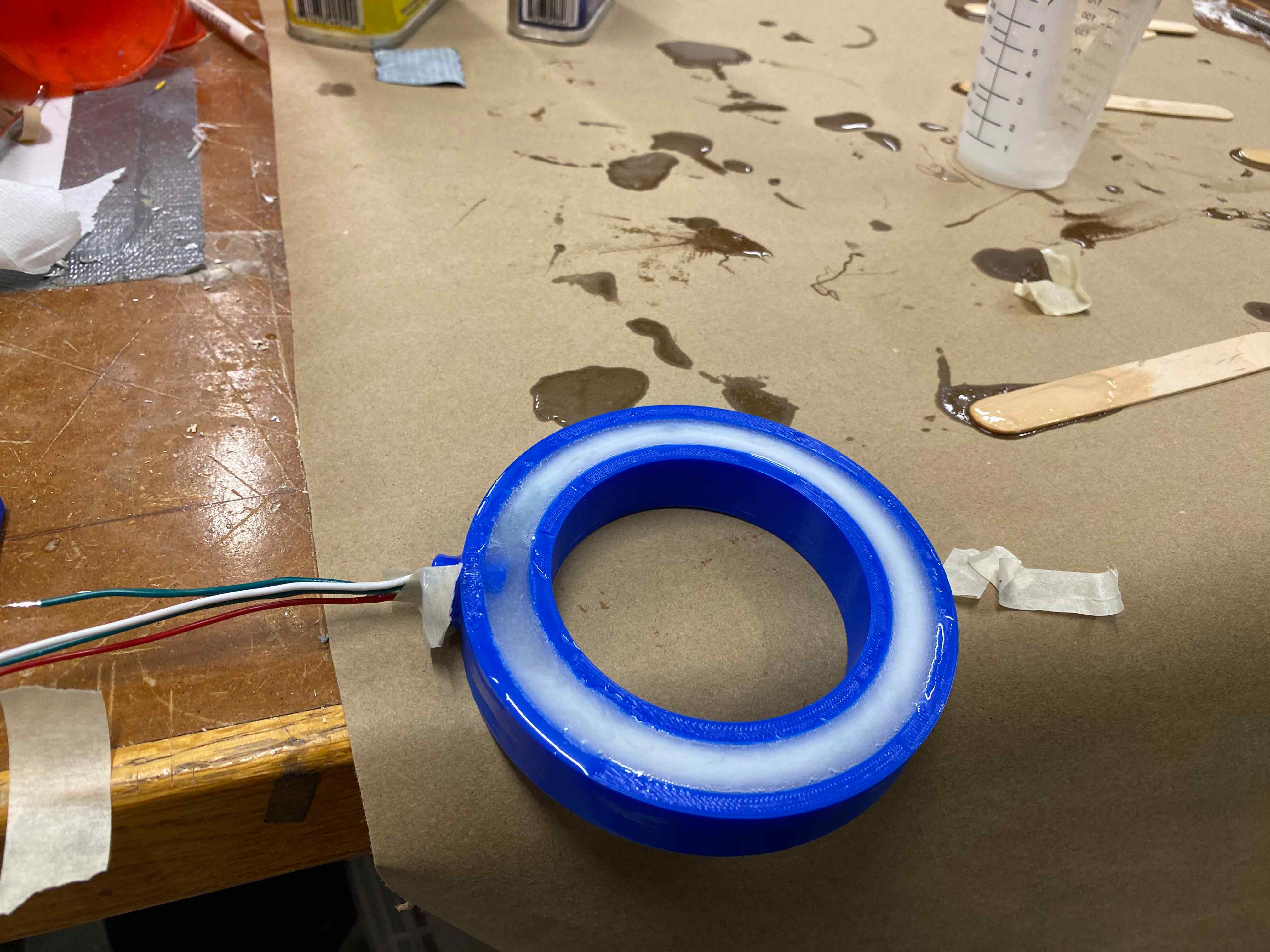
Print molds for the hoop encasing and ball. Place the coil and LED strip into the hoop mold and the magnet in the ball mold. Mix epoxy and pour. Wait until cured then use a chisel to remove the molds. Sand pieces but be careful not to sand any exposed wire.


Cut PVC to desired length. Design base using press-fit joints and laser cut acrylic. Assemble pieces and clean up wire by cutting and crimping into 2x3 header.
At the beginning of the semester, I considered an inflatable hoop but had dismissed it quickly after finding no good resources for custom inflatables. Well, to my utter shock, there is a wildcard week on inflatables! I can see this being revolutionary for the world of quidditch, seeing as the hoops are by far the most annoying aspect of equipment. Carrying six wooden bases, hula hoops, and PVC poles across the river gets insanely tiring. These are also built to break apart and fall down when hit, which means someone has to set it back up after almost every half court. A set of inflatable hoops would be orders of magnitude lighter, (slightly counterintuitively) more robust. If I have time, I will try to incorporate the magnet wire and LED strips in an inflatable hoop.
Later update: I did not end up incorporating the inflatable hoop, but see Week 13 for the process!
Here's an idea I have for the scoring detection: Faraday's law! Since the hoop is circular, I can coil copper wire (or tape if it needs to be flexible) and then attach a magnet to the ball. A voltage proportional to the change in flux over time should appear as the magnet passes through. This will definitely need to undergo small-scale testing first. I will experiment with a small coil and magnet to see if I can register any difference in voltage on a SAMD11C.
Small scale testing works, but I'm skeptical as to whether this will work with a bigger loop size.
I used my breakout board from Week 8 and Rob Hart's tutorial for step response. My order for N52 magnets arrived, so I used a stack of these, which was a lot stronger than the ones I tested with previously. On the serial plotter, you can see the graph dip when the magnet is moving through the coil.
Since I am not too good with theoretical physics, I contacted my uncle with some of my questions.
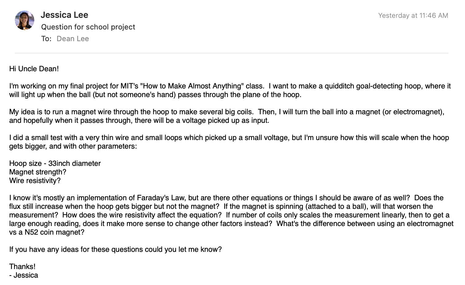
My uncle responded, and the main takeaways were: hoop size will affect the angle of change of flux, and N52 magnets are better than small electromagnets. Professor Gershenfeld similarly warned that the hoop size would affect the measurement inverse cubically, so I should aim to coil the wire about 100 times.
I quickly threw together a laser cut square design with the same perimeter as the hoop. I had a few screws poking out to wind the wire around.

Passing a magnet through did not work at all, unfortunately.
This was discouraging and stumped me for a little bit. Quentin suggested that I use an opamp to amplify the voltage. Upon making the board and testing it out, it immediately started smoking.
I then thought about making the hoop a giant electromagnet and putting a Hall sensor on the ball. However, after trying out a quick test with the component on my breakout board, I found that it doesn't have nearly enough sensitivity or range to work in this case.
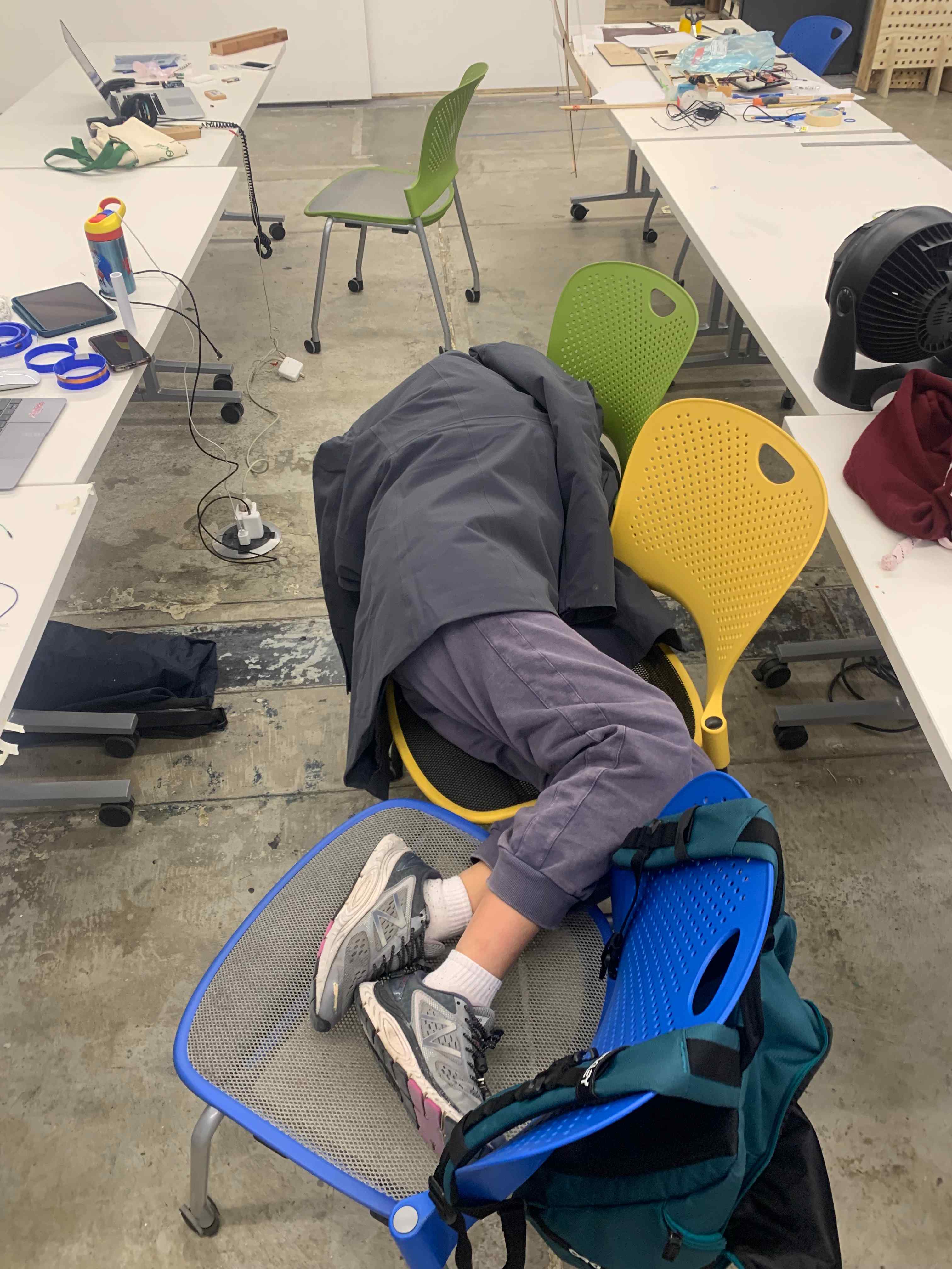
Nap break! (In the last week, I ended up sleeping in the lab for four days straight)

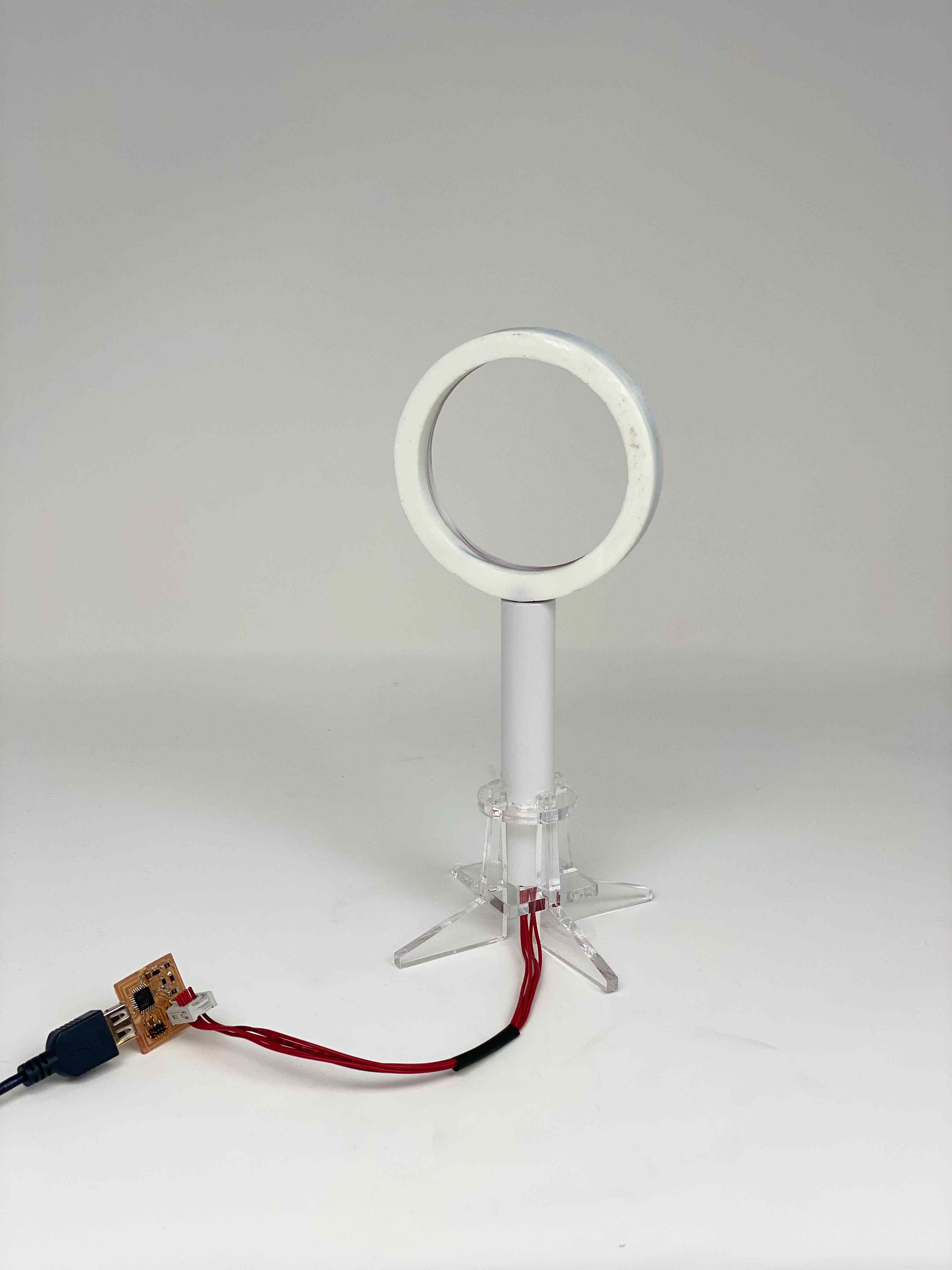
I settled for making a small hoop. Using parameters in Fusion 360, it was very straightforward to make a 1/10 scale model.

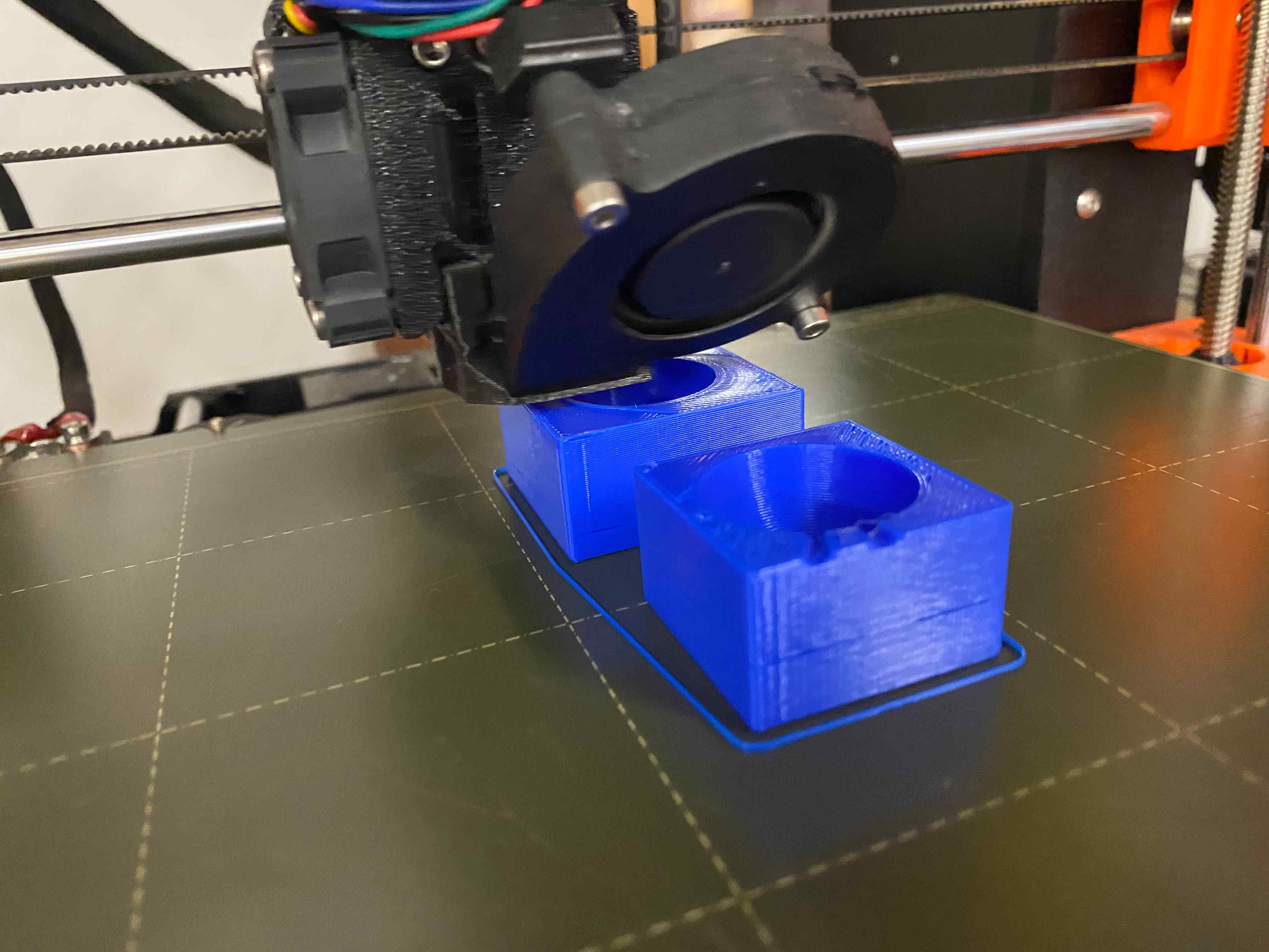
3D printing the molds did not take much time at all. The hoop mold was printed at 0% fill because it will eventually be broken off.
Just as I was ready to cast the hoop, the step response stopped working. I made several new coils, none of which worked. When I tested the original smallest coil, it also didn't work, which was very suspicious. I spent many hours trying to figure out what was wrong. Eventually, after testing the board with a multimeter, I found a short between Tx and Rx beneath a 0 ohm jumper.
I was nervous about casting because I didn't know how the electronics would hold up I made sure to test the code immediately before and after pouring the epoxy. To my delight, it worked! It also seemed like casting stopped the coil from shifting and actually reduced noise and made the measurement cleaner!
After breaking the molds (which was quite a workout), all that remained was the base. I decided to laser cut in order to satisfy the subtractive process requirement. I found leftover acrylic near the laser cutter and threw together a quick design in Fusion 360. My thickness measurement was a little bit off, so the press fit didn't work as well as intended, but it did the job.
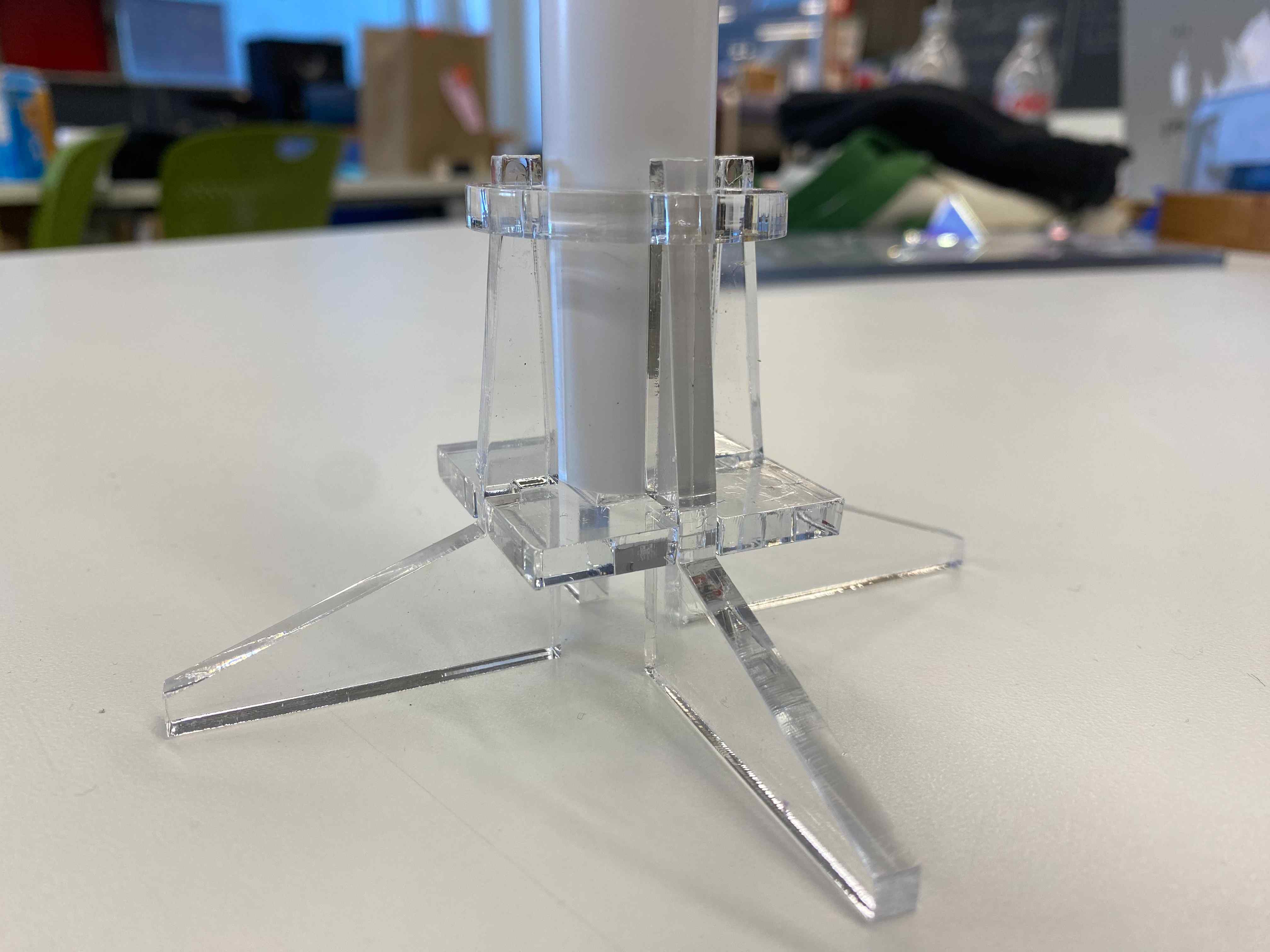
I found some spare PVC and cut it to size. I threaded the wires through to measure length then crimped on a header. The design is extremely portable and fits in a small ziploc bag.
