Week 02 - Electronics Production
1.1 Group Assignment
1.2 Individual Assignment
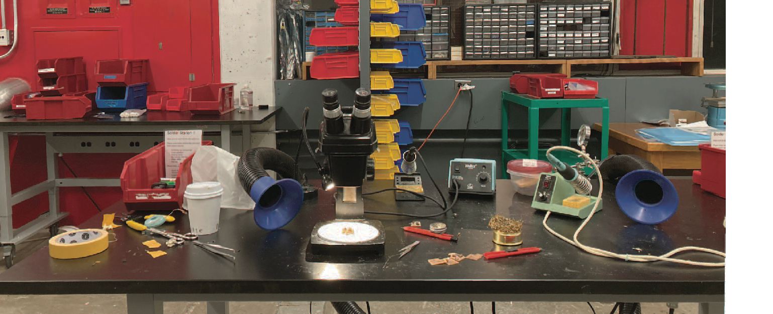
Our assignment was to characterize the design rules for our PCB production to understand the characteristics of the end mill, the milled material and the milling machine. To do that, we milled a test strip, where the traces and gaps progressively increased from 1 to 20 mils.
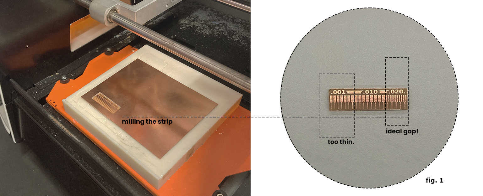 We found out that the machine performed its best in producing traces as thin as 8 mils. The traces finer than 8 mils had a higher risk of pulling out (as it can be realized from the bottom parts -see fig.1). Also, the gaps between traces performed best when the gap was 16 mils minimum (We have used the 1/64-in end mill, which is 15.625 mills, it corresponds to the optimal gap).
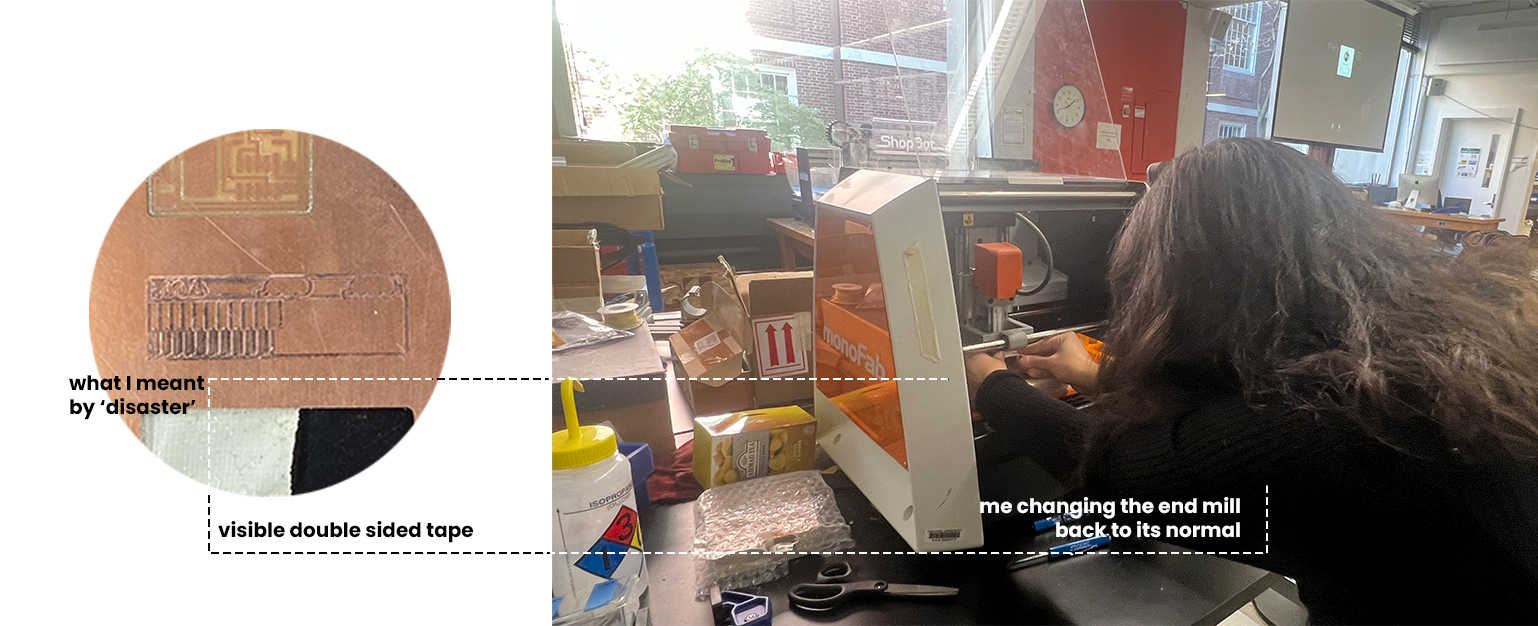
We also tried milling the traces with 1/32 in end mill, which turned out to be a disaster. The traces were very thick and undefined. It was only for testing the end mills, thus, we stopped the machine before milling process terminated.
1.1 Group Assignment
1.2 Individual Assignment
The individual assignment was to make an in-circuit programmer (in our case, USB-D11C-SWD-10 pin), which includes a microcontroller.
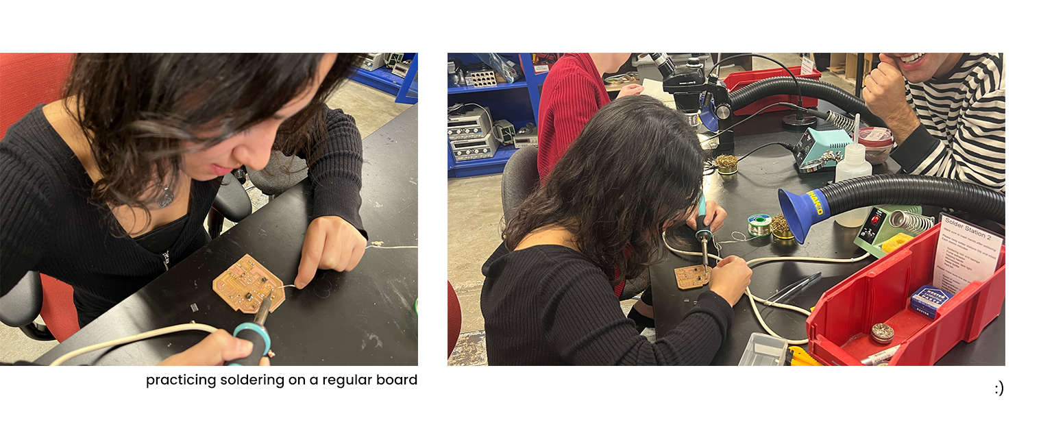
My first interaction with soldering was brief but promising, especially when TAs Nathan and Leo demonstrated the process and let us have our moment with soldering during this week's Thursday meeting session. After succeeding in my first attempt there, I thought it would be -easy. In Italian, there is a sarcastic way of saying "you wish": Magari.
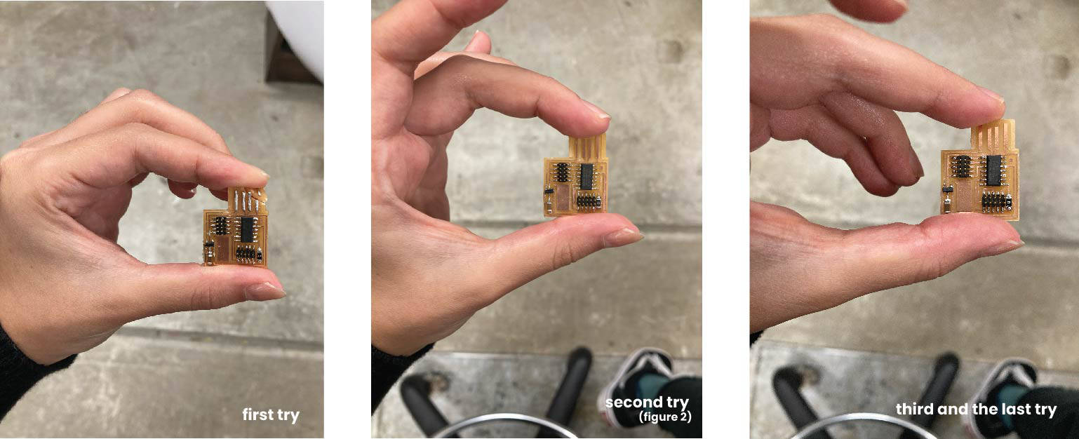
It took me 3 PCB tryouts and 20 hours at the lab. Easy. Ha-ha.
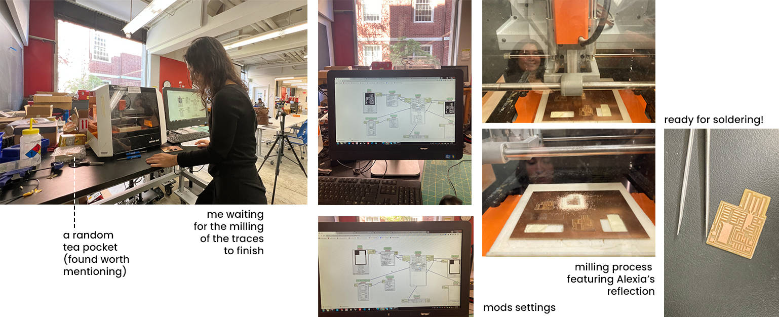 It all began on a Saturday afternoon, as we started milling our boards, which did not look well-traced at the first attempt (I believed I did not stick the board to the layer tight enough), so I did it again. Taking my board to the solder station, I pulled off some of the copper traces surrounding the USB entrance with a knife: this was a lot more time and effort-demanding than expected.
The First Attempt
After practicing soldering on other boards, I started soldering the actual board. I thought I did well. The next step was to check if it worked as a programmer. In order to test this, I needed another already programmed PCB. Treyden Chiaravalloti had an already programmed PCB, so we tried and tried, and t r i e d. Until 10 pm. It did not work. Adding to that, we could not find what the issue was, whether the problem was one of the connections or not. Thus, I decided to consult with a TA the next day.
 Second Attempt, Second Day
 TA could not find the reason as well. We did not even try testing the connections with a multimeter. Suvin (TA) assumed I had probably fried one of the components, so I had to start making a new PCB. TA informed me that frying is most likely to happen when a heat gun is used.
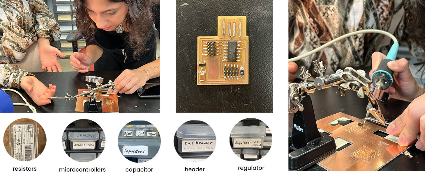 At that moment, another friend at the lab was cutting multiple boards to practice. He kindly offered to give one of them to me to start the process faster. He was cutting numerous boards at the same time, as I mentioned. And the traces were not well separated in many of them. I tried cutting the traces, which had to be separated, using a knife. It worked, but I screwed up at the transistor soldering (see fig. 2). I tried to desolder, but the whole PCB looked so messy to me, so I decided to cut one more board on my own, use the microscope and do it really well this time.
 Final Attempt (Success)
After
Calmly milling the board,
Scratching and pulling off the USB entrance's copper layer parts,
Settling into my workspace,
Opening up the fume extractor,
Turning on the solder gun machine,
Turning on the lighting,
Picking up two tweezers,
I put a double tape under my board, placed it on the microscope bed, and
started working.
 And finally, the result happily correlated with my desired outcome.
 Verifying If PCB Works
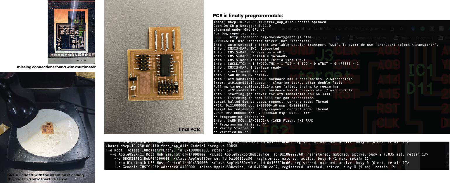
Cedric was at the lab around that time and had a PCB that was already programmed and working. We connected my PCB to his board with a programmer. The computer could read the board, but an error ‘Info: at91samd11c14a.cpu: hardware has 4 breakpoints, 2 watchpoints’ occurred. At the Open OCD forum, it was stated this was successful because it implied that it ‘found the openocd.cfg file, read that, and use it to program the .bin file onto my microcontroller’ . However, Cedric’s computer could not read my PCB as a USB. There was definitely a problem with one of my connections. Therefore, we began checking all of the connections with the multimeter.
One of the headers had a problem. To make the connection sturdier, I thickened the bulbs by adding more solder. We tried again: there was progress in one of the connections, but the computer was still not reading my PCB as a USB. Then we found it. One of the heathers was floating, not even touching the board……………
I went to the soldering station for the last time that day and stuck the header to the board, adding a bit more solder without attaching any connections together. We tried again and… success.
After a week of frying and floating components,
I made my first circuit board.