Week 08 - Input Devices
-
-
Loading!
2. Accelerometers and Microphones
Disclaimer Before Beginning to Read: This is a self-made promise that I will revise this week as soon as possible.
Individual Assignment of this week was to measure something: add a sensor to a microcontroller board that you have designed and read it.
This week was… challenging. I re-questioned ‘(almost)’ all my values I had for the final project. The questioning started in the molding and casting week, due to simply not feeling good about my wearable instrument idea being a conventional and highly repeated glove-shape. I still feel excited about creating a wearable-or `step-able` that changes& loops certain properties of my sound.
For this week, I wanted to experiment with a 3-axis accelerometer for the wearable system as well as a microphone, which I thought I could connect to an output speaker device next week.
Both for the accelerometer and the microphone, my idea was to blink the LED on my SAMD21 devkit when the sound or the distance passes a threshold, which Quentin showed me a day before.
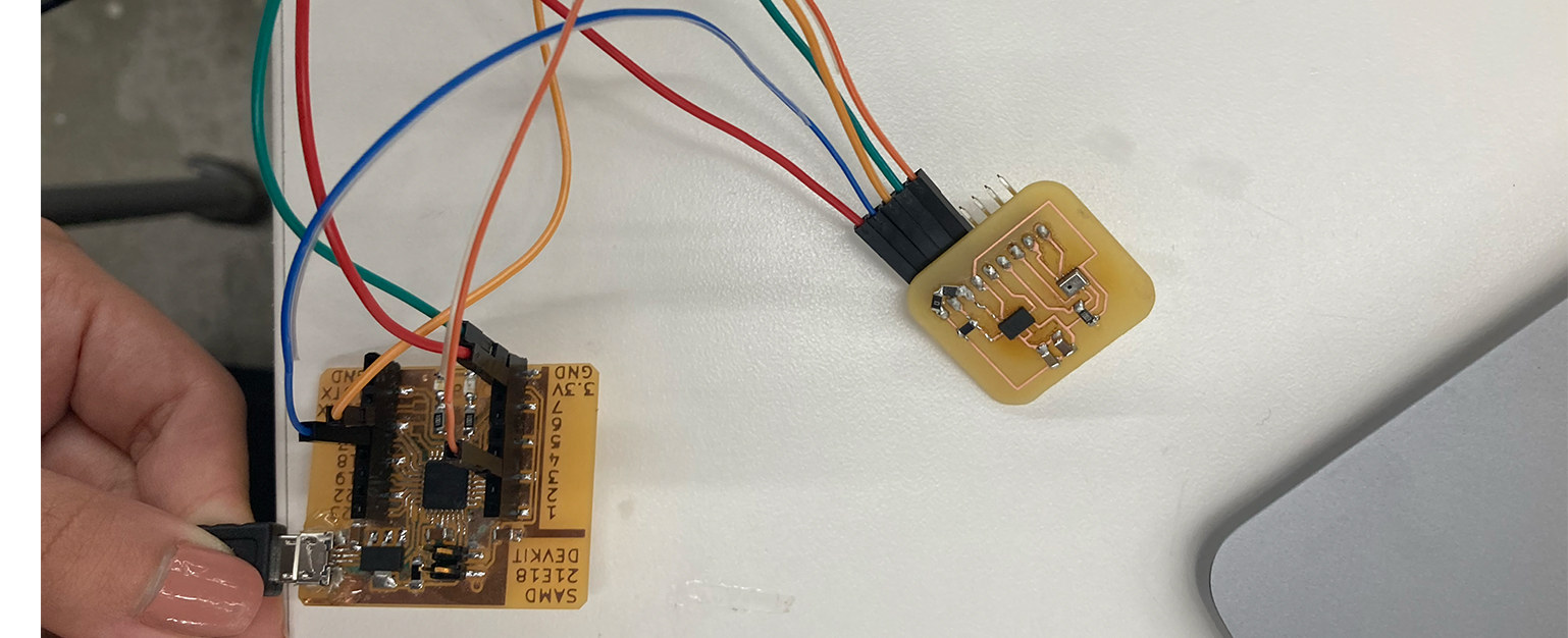
I already had my designed board but it had ATSAMD11C as a microcontroller, thus, I decided to use the SAMD21E18A Devkit board that I milled a couple of weeks ago, which is Quentin’s design. However, I needed to design my own break-out board.
For the accelerometer, I chose to use ADXLR 343, which was a 3-axis accelerometer. Even though I might need a 6-axis one if I want to do a more-sophisticated wearable, I thought it could be a good start.
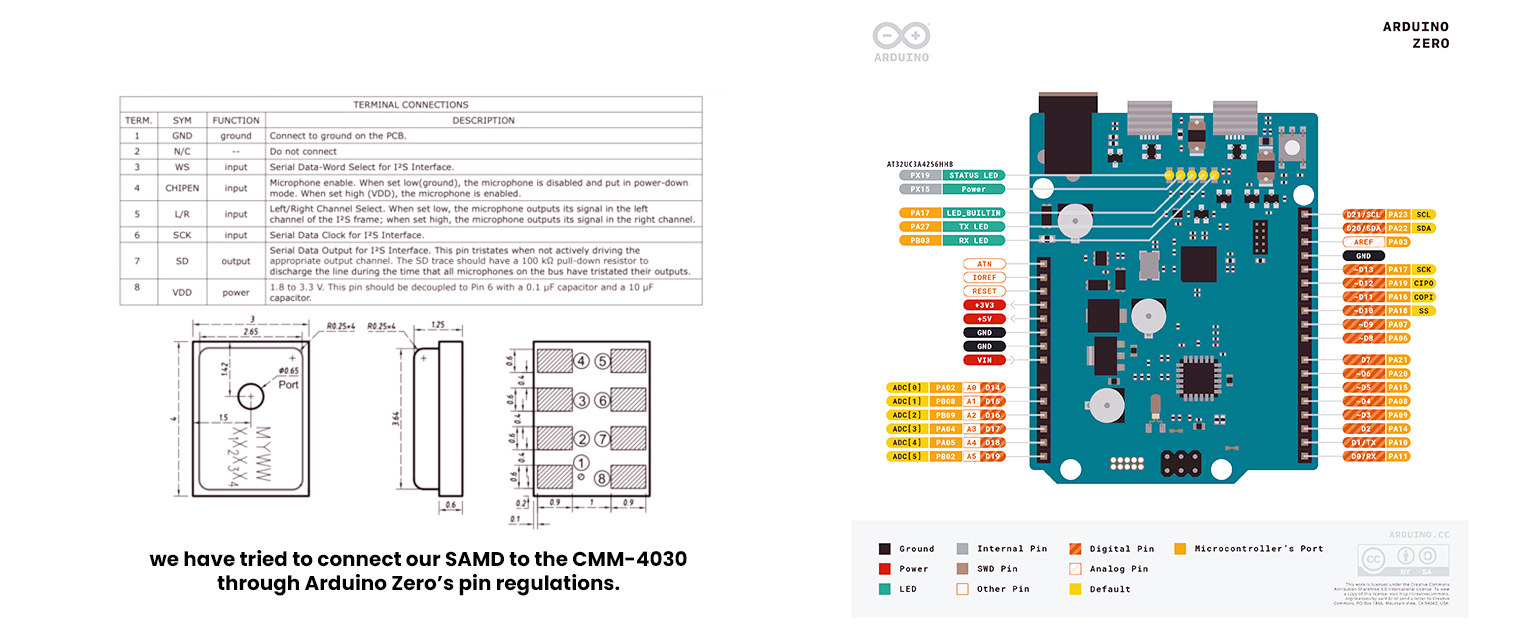
For the microphone, I took a risk. Because the mic I wanted to use, CMM-4030D-261-I2S-TR,
was never used with a SAMD21 before at our lab, even though it was indicated that it was possible.
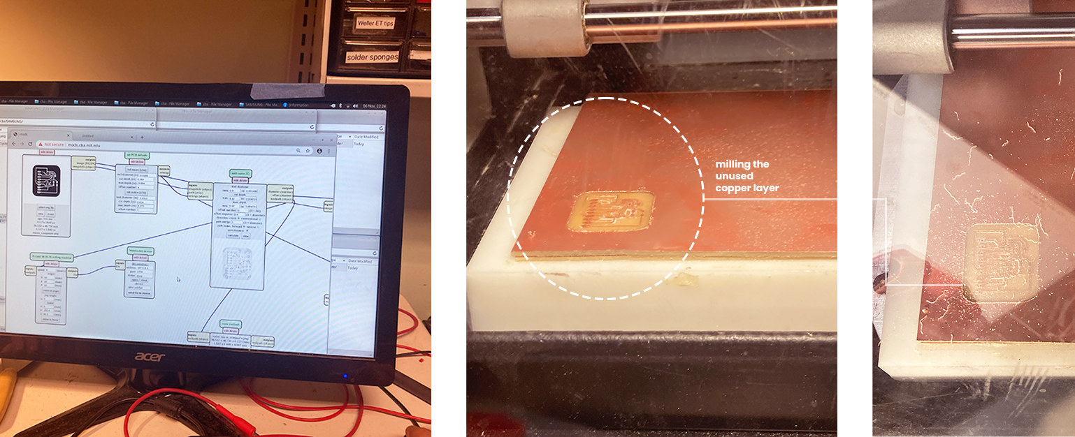
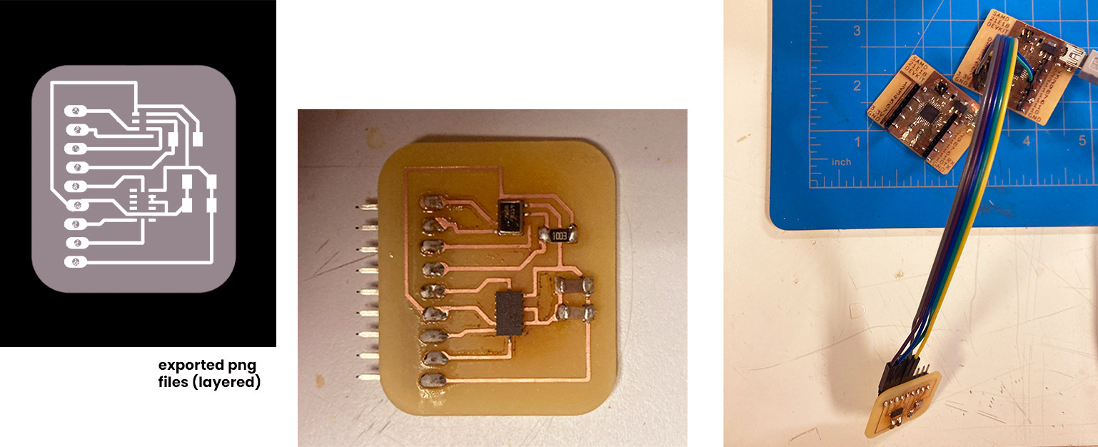
I started the CAD design for my breakout board using Eagle. Some of the pin pads of the accelerometer had to be smaller, so, I edited the footprint with Quentin. I passed directly to the milling phase after that. This time my resolution was 1000 dpi instead of 800, making sure that the milling was as precise as it can be.
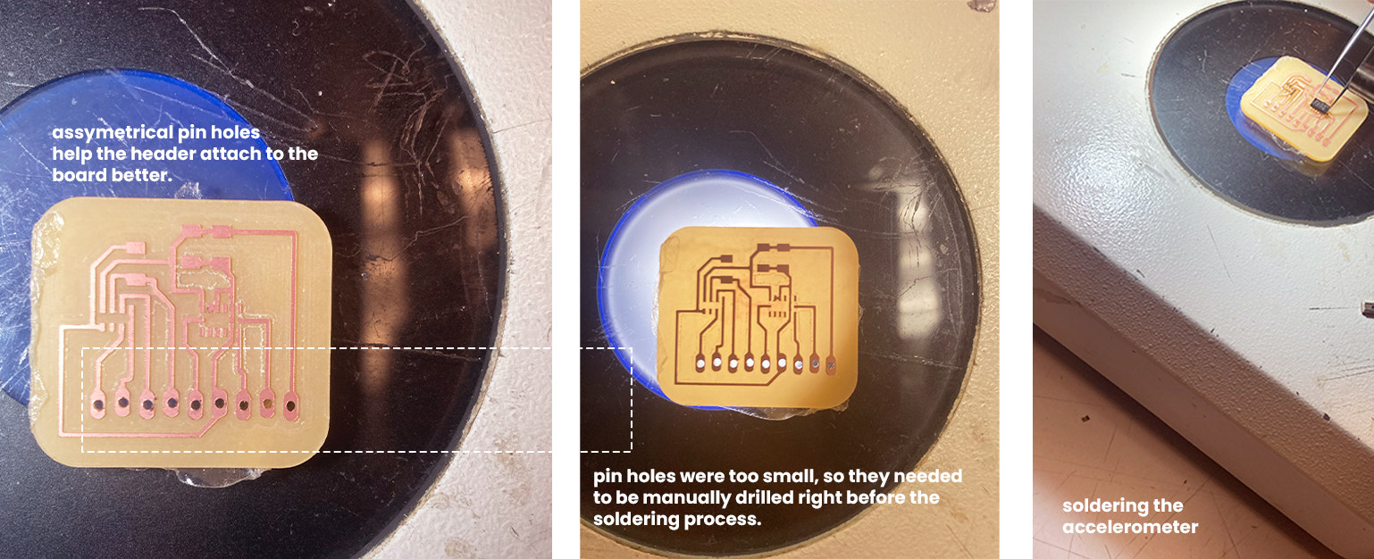
 Soldering phase was slightly harder than any other soldering process: Both microphone and accelerometer were very small. Thus, we had to add solder on each pad first and then attach the components through hot air gun, with a lot of attention to not fry it.
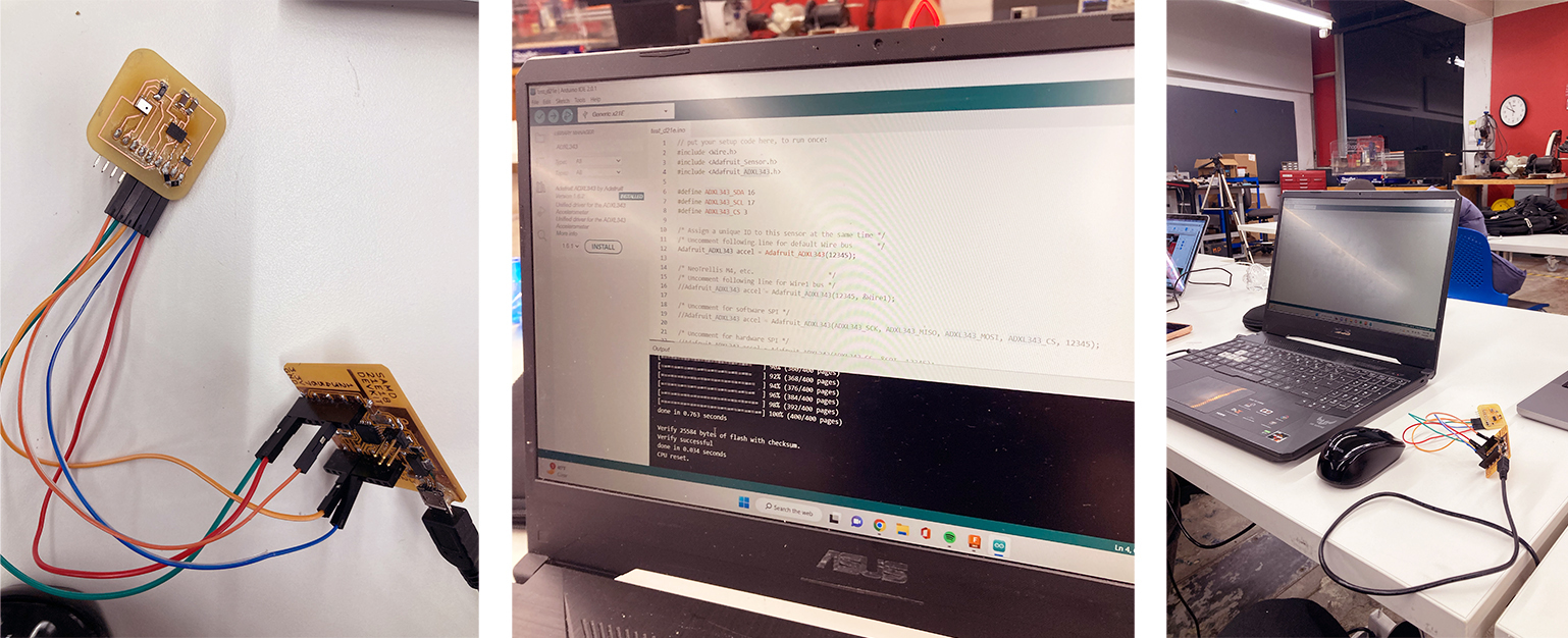
After everything was finished, I have connected my board to the breakout board for the accelerometer first. I had to install a couple of library ADXLR_343. Then, I have opened the I2C Scanner to see if both of the boards were detected. My main board was detected, but the breakout board was not.
I wanted to understand if it was the breakout board that caused the issue, so, I tried to read the accelerometer with Claire’s breakout board, which also had the ADXLR_343. And it worked! It was now clear that my board had an issue. Actually, issues.
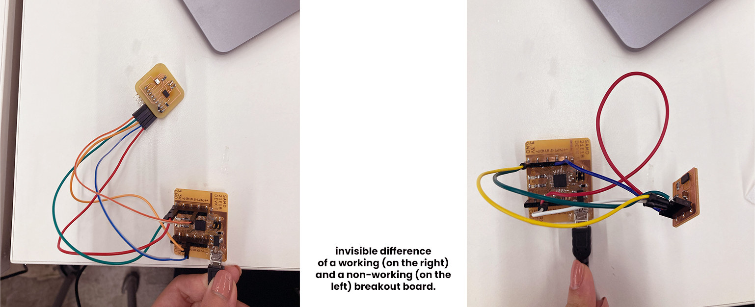 First problem: I didn’t add 10k resistors for the accelerometer. It needed one for SDA to VDD and one for SCL.
 Quentin also helped me during this process, and added a 0 ohm resistor to connect the 10k resistor. However, the board did not work again.
I turned back to the CAD design and rechecked everything, and there it was: the problem. I designed the accelerometer 180 degrees flipped!
There was only one option now: Desoldering the accelerometer and experimenting with the digital microphone.
Adafruit only works only with the SAMD21.
 We can call the microphone phase a constant attempt of keeping our hopes high.
First, it was really challenging to find the pins corresponding to the SAMD21. We found an Arduino Zero and were able to make it work. Using Neil’s code, we tried to change the pin names that could be compatible with Arduino Zero.
Long word short, it did not work YET. Looking forward to debugging it. To be continued! :’)