Week 11
Networking and Communication.
Engineering Files
Radio Frequency Signalling Between Xiaos
For this week's assignment, we were tasked with testing different communication signals between sensors, actuators, and processors. Because the past few weeks already involved using SPI, UART, and I2C connections to interface with the sensors I'd been using, I wanted to try and use wireless communication for this week's project, and interface with the projects I made the prior week.
From the electronics available in the architecture sections, I grabbed two nRF24L01 modules to communicate between my two Xiao boards - my trusty one I milled a breakout board for, and another one I had connected to a breadboard.
The radio frequency modules look like this, and have a pretty impressive range of communication capabilities:
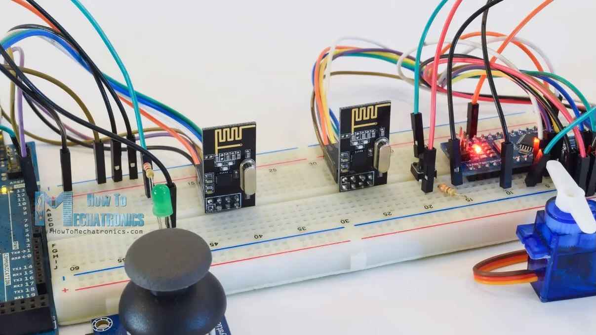
I found a great tutorial for the modules here, which detailed a lot of the functionality available.
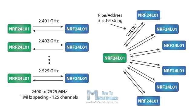
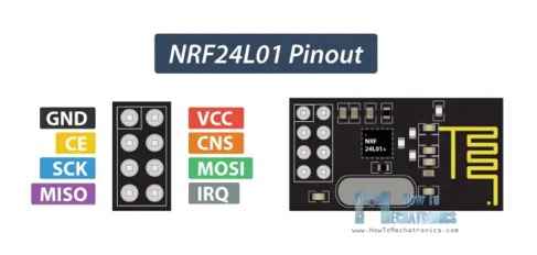
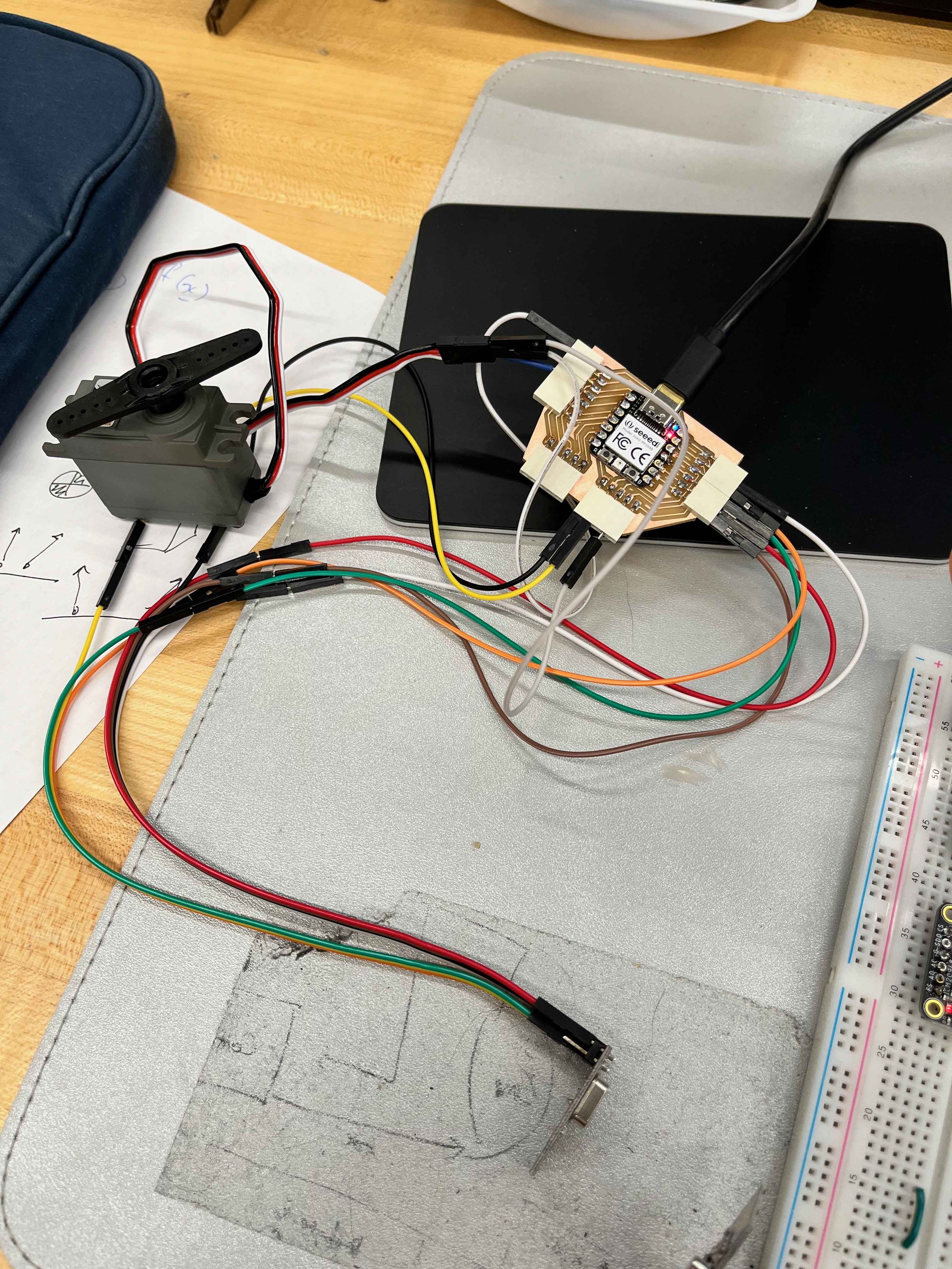
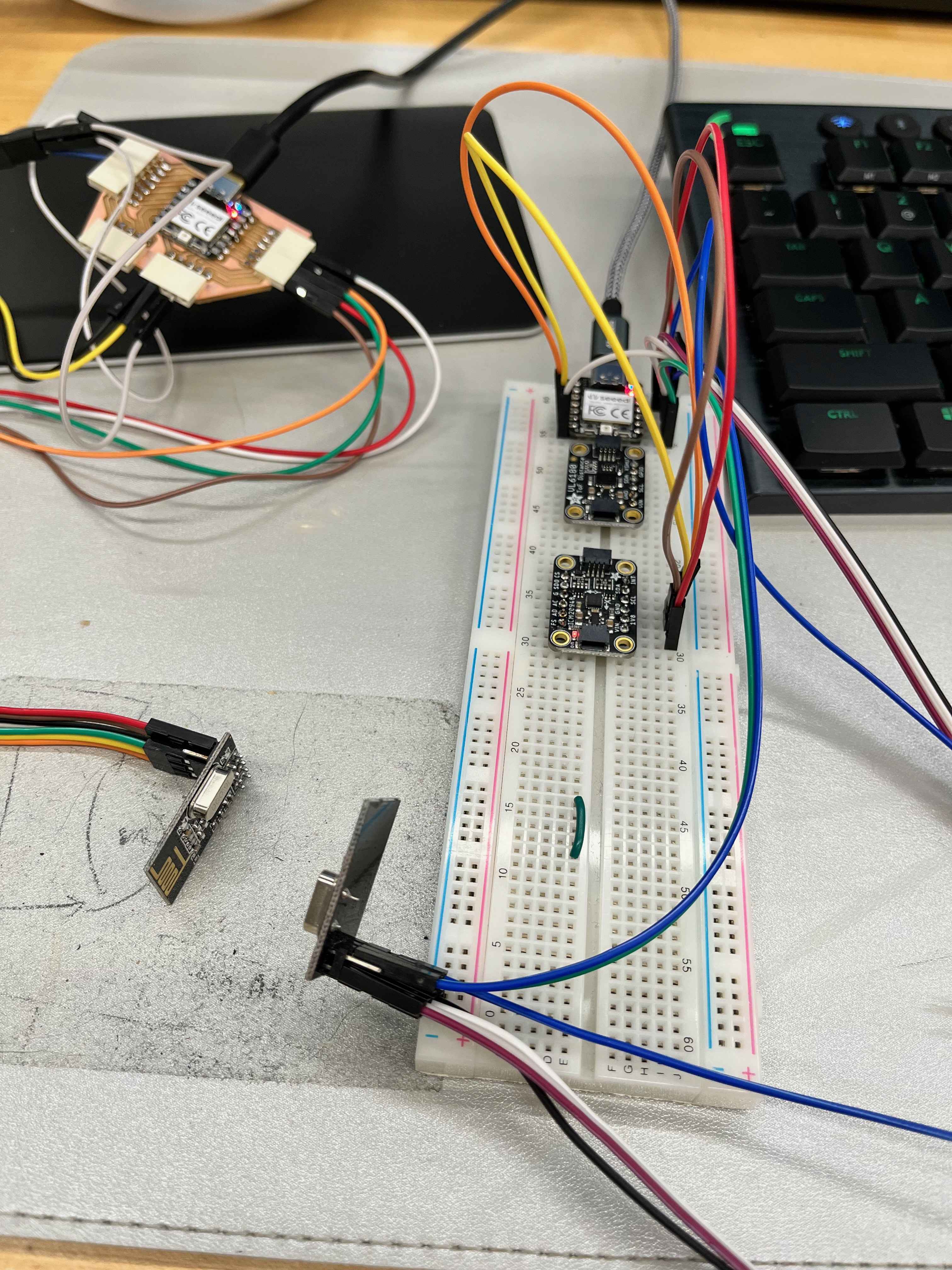
With all the pins required from the radio module, I only just had enough room on my breakout board to fit it. I'm still not sure how useful using RF is when I could just use a wired connection, but it was a fun exercise to try out. I decided to connect an IMU to my breadboarded Xiao, and use the IMU to send acceleration values to my breakout board Xiao.
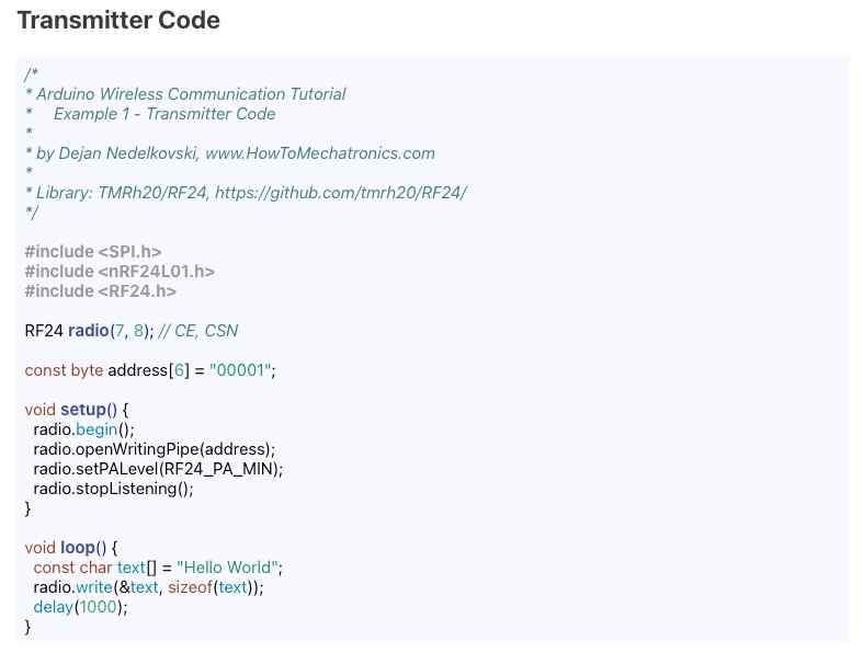
I used the RF24 library for Arduino, and found that the example code was pretty straightforward to use. I used the "Getting Started" example code to test the connection between the two boards, and found that I could send and receive messages between the two boards.
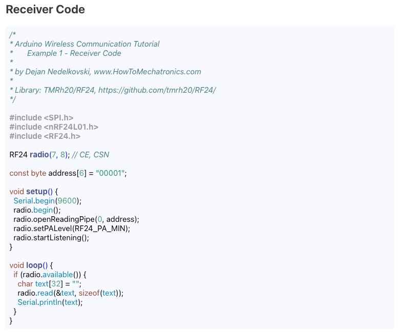
The final wiring looked a bit chaotic, but it was functional:
A recording of the readouts from the IMU can be found here:
How to Make Almost Anything 2023