Assignments
The individual assignments for this week are:
- add an output device to a microcontroller board you’ve designed, and program it to do something
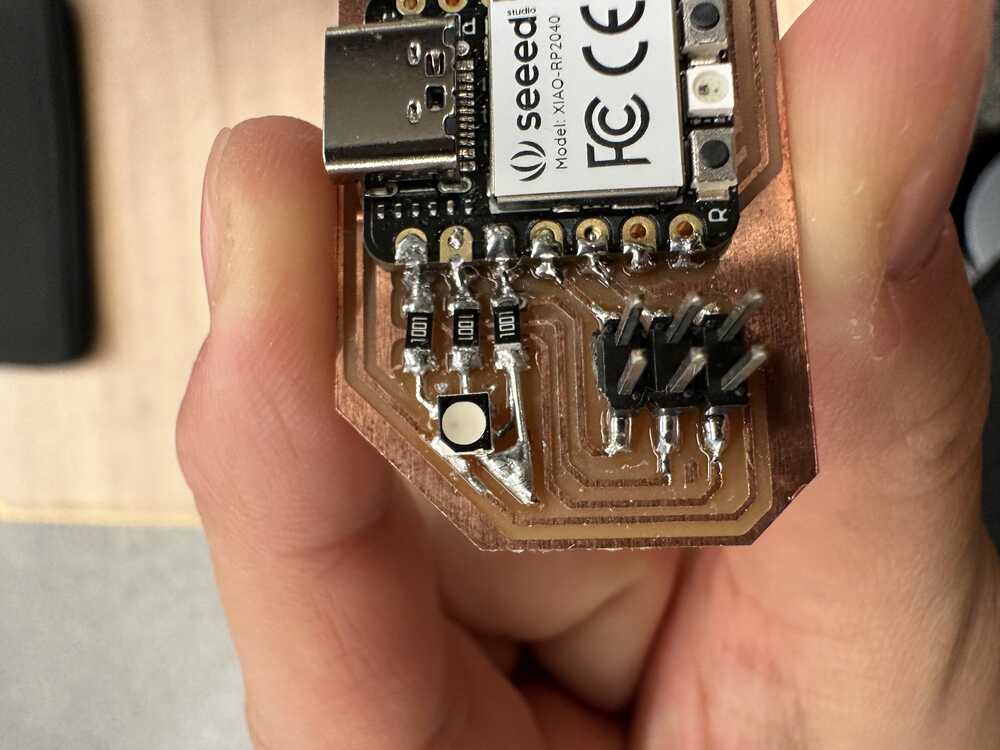
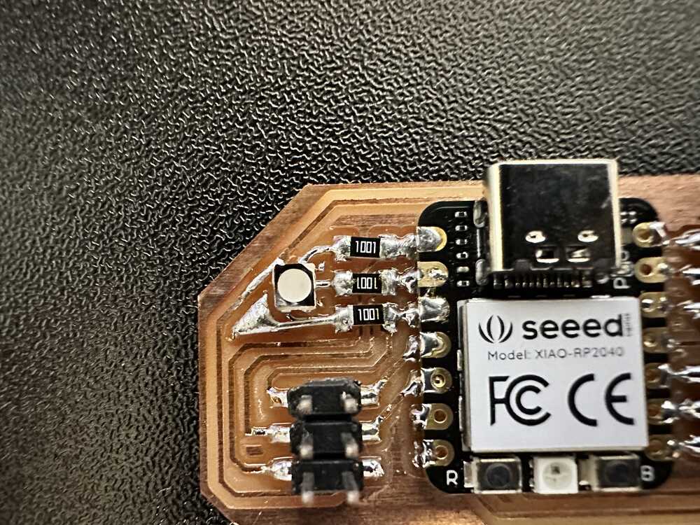
Preparing the board
In the PCB making week, I made a board that had a common anode RGB LED on the board. The package had four pins, one under each corner, and a notch in one of the corners for figuring out the orientation. Unfortunately, I just assumed that the common anode pin was under the pin with the notch, and soldered it in that way. In actuality, the common anode pin was under the corner one away counter-clockwise from the notched corner.
With Alec’s help, I used the hot air gun to melt the solder (hot air set to 290C) and remove the LED. Then, we rotated the LED into its correct place and set it right above where it should go. Then we turned on the hot air again and blew hot air at the LED again, and continued blowing hot air at it for a few seconds after the solder had visibly melted, to ensure that all four soldering joints melted and made a connection with the LED.
Turning on the LED
Now that the board was ready, I modified my code from the development boards week to not use the built in LED on the seeed rp2040, but rather to control the LED for the board using the pins that I had connected to it. One thing that took a while to debug was that the pinout diagram on the seeed website for the xiao rp2040 had multiple names for the pins, and in order to actually specify which pins I wanted to control, I needed to figure out what pins they actually were in the code.
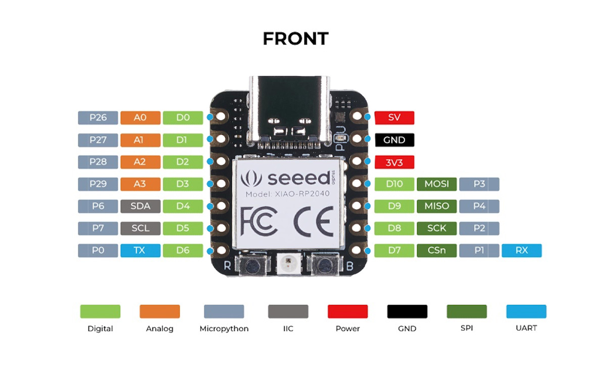
e.g. I used pins D0 D1 D2 to control my RGB LED, however, if I tried to use the following code,
pinMode(0,OUTPUT);
digitalWrite(0, HIGH);
nothing would happen and the pins would stay floating. In fact, if I wanted to specify the pin not by the moniker “D0”, I had to use
pinMode(26,OUTPUT);
digitalWrite(26, HIGH);
instead, since pin 26 on the microcontroller is the name of the pin that connects to the xiao’s pin 0.
Alternatively, Arduino (specfically the library for the xiao board), also predefines constants for the pins, so the code
pinMode(D0,OUTPUT);
digitalWrite(D0, HIGH);
works as well.
Additionally, since the common anode pin is connected to 3.3V, to turn on a channel of the LED, I had to set its corresponding pin to LOW (0V).
Thus, I had to set the pins to be LOW when I wanted to turn them on, and HIGH when I wanted to turn them off.
Outputting in Morse Code
After figuring out the connections to the board that I wanted, I simply uploaded the modified code and opened serial monitor to start my code.
A demo of it printing out my name in morse code is shown below.