Video
Ideas
- Keyboard Tray
- Making a custom speaker setup
- Personal stream deck
- Boxing dummy alarm clock
- Phone automator
- osu! player?
- Hangboard/Moonboard
My original idea for the final project was to build a custom attachment for my standing desk. I wanted to make something that would let me use the ergonomic keyboard that I liked, while simultaneously not cluttering up my desk and complementing my current workflow.
More about one of my initial ideas can be seen in my week one post.
Making a smart hangboard
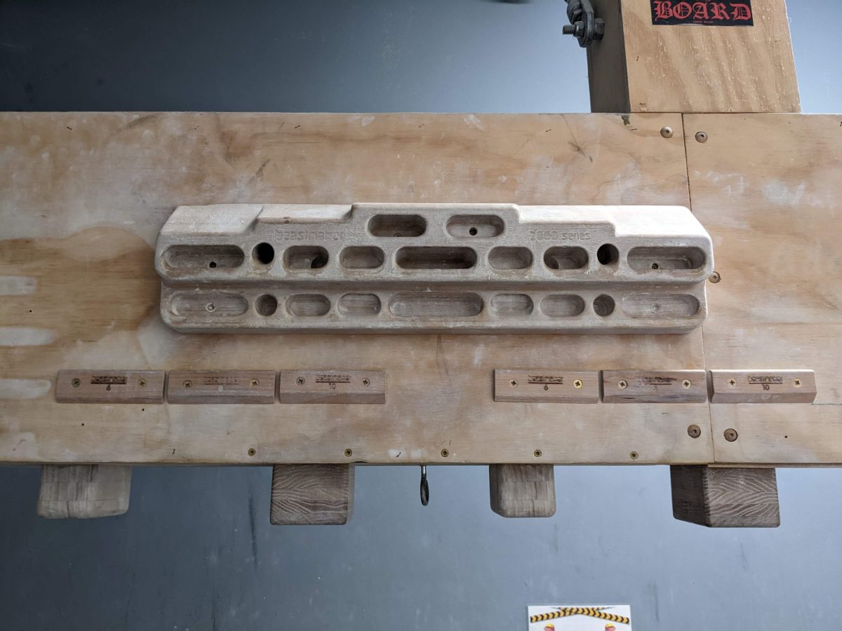
A hobby that I have been really getting into lately is bouldering, so I want to make something related to climbing.
One thing that I always found really cool is a Moonboard, which is essentially a programmable wall with a grid of many holds. Millions of problems can be made on that board by setting which holds light up.
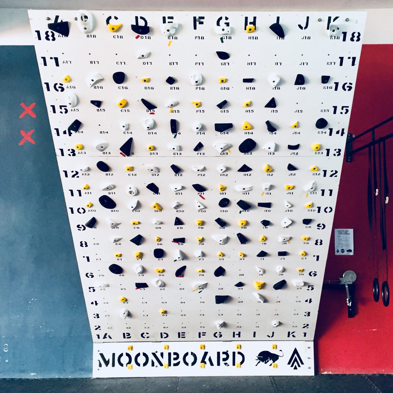
I originally wanted to make my own cheaper version of a Moonboard so I can practice in my own room, but I realized that my room is much too small for a Moonboard, and I mostly just want to make something to practice on outside of the climbing gyms. Something closer to a hangboard?
Anthony told me that a previous student, Alejandro Diaz made a climbing wall for his project. I will be using some of his project notes for guidance. I don’t have the same amount of space as he did (he had a whole backyard), so I won’t be building something as large as his.
A Smart Hangboard
For the reasons above, I want to make a smart hangboard. And I want it to have a few features:
- interchangable holds: I can switch out holds to practice on easily
- multiple levels: so I can practice reaching upwards for holds
- detection of which holds are in use
A goal feature would be a way to gamify the board, e.g. certain holds would be indicated as “goals” you have to position your body in a way to touch all of the goal holds simultaneously.
Resources
A lot of the thinking that went into this project was actually just reading how others have built climbing walls of their own. If you wanted to build your own and didn’t know where to start, I find that these pages are all great resources to look at!
And various other ones that are relevant
- Alejandro’s
- Emma Kowal’s climbing wall
- Instructables
- REI blog
- Guy who built a hangboard in his house
Update 11/28
My current plan is to have the hangboard look like an upside down T-shape, with holds to the side and higher in the middle. I feel like a design like this will let me practice most moves: going up, down, sideways, and diagonally. I can practice a lot of campusing type moves, as well as just statically hold onto it.
My current plan is to have up to 21 holds, each with its own capacitive sensors. After consulting with Anthony, I decided that I would use 3 xiao ESP32S3 boards, for a couple reasons: first, they have significantly more analog pins than the ESP32C3 or RP2040’s, and they also have better quality analog sensors than the RP2040 (according to Anthony).
These devices would all be on a single board, and would talk to each other via I2C. I also broke out an I2C header for a display, if I wanted to also have a display.
Final Week Schedule
Wed Dec 13
Design structure and finish ordering parts/tools Wood, connectors, screws.
Thurs Dec 14
Design molds and holds
Friday Dec 15
Programming microcontroller/finish holds
Saturday Dec 16
Visit home depot/Build structure
Sunday Dec 17
Attach holds and connect microcontroller
Monday Dec 18
Debug
Tuesday Dec 19
Profit???
Actual Schedule
Wed Dec 13
Formalized design consulting with Anthony. Decided on 4’x4’ wall, with a frame behind it composed of 2x4’s. Since the structure is not what I will be presenting on, I will table it for now while I figure out the crux of the project, which is the actual wall and holds itself.
Thurs Dec 14
Visited Home Depot and purchased plywood and hardware for building the frame. Started printing first hold on Prusa with PETG. More details in notes.
Purchase list from Home Depot:
- 4’x4’x23/32” sheet of BC plywood (I couldn’t find ACX plywood)
- Box of 3” decking screws for the frame
- Four 80 degree corner connectors
- Box of 1 5/8” screws that fit the corner connector holes
- Box of shorter screws
A Break
They say plans are worthless, but planning is everything. This couldn’t be more true for this project. My progress on this project was completely derailed on the night of Dec 14 due to personal reasons and left school early.
The next time that I found the time to work on the project was next year in January. For the rest of the project work, I’ll give rough dates, since the exact dates don’t really matter.
January
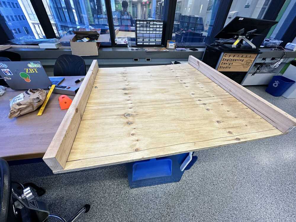
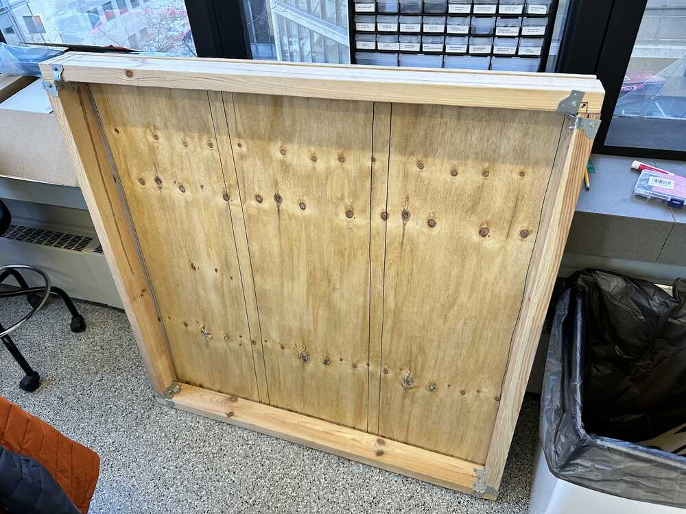
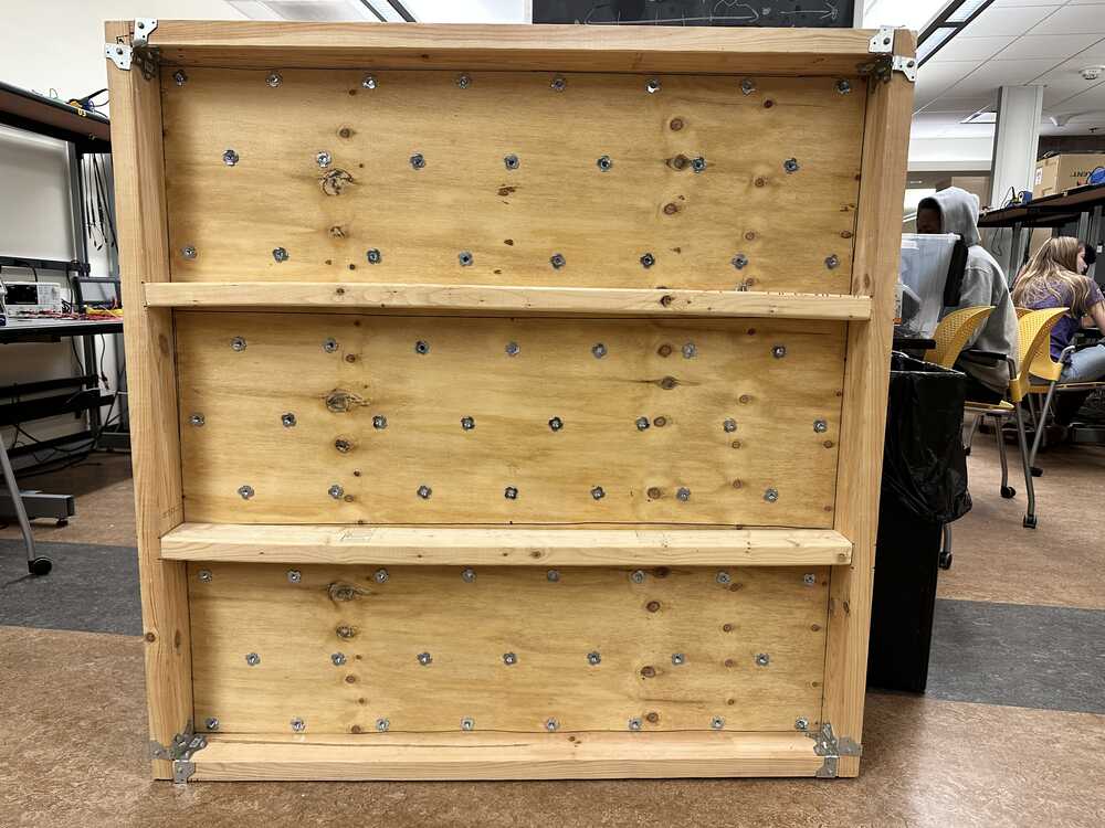
Over the course of a few days, a couple of hours at a time, I finished the “physical” part of the wall, which consisted of building the structural frame behind the wall and attaching it to the plywood sheet, and drilling holes for the T-nuts, and mounting the T-nuts.
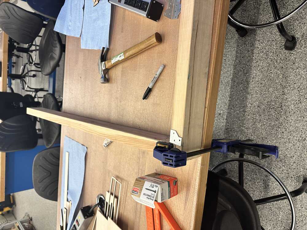
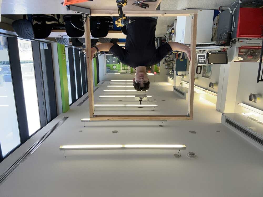
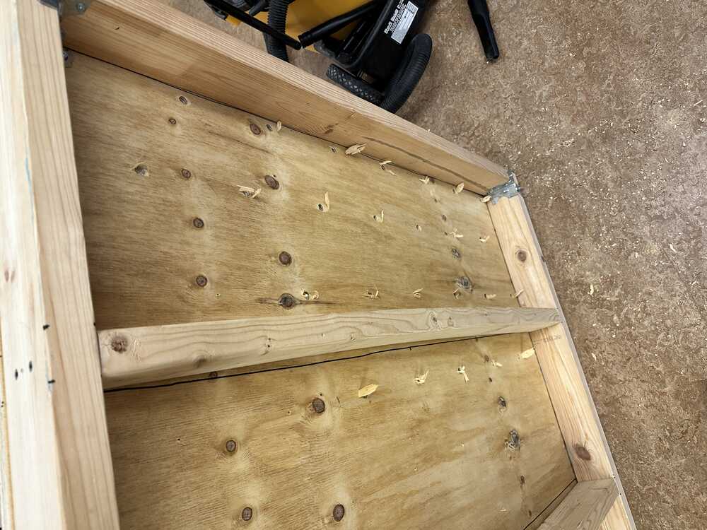
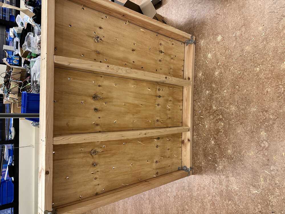
I started by carefully measuring out the correct lengths of scrap 2x4 that Anthony had lying around to build the frame with. Using a hand saw and some clamps, I cut six pieces, four for the frame that would perfectly inscribe the plywood sheet, and two evenly spaced studs in the middle.
I first connected the four outside pieces of the frame using the corner connectors and short screws.
Then I wedged in the two studs into their places
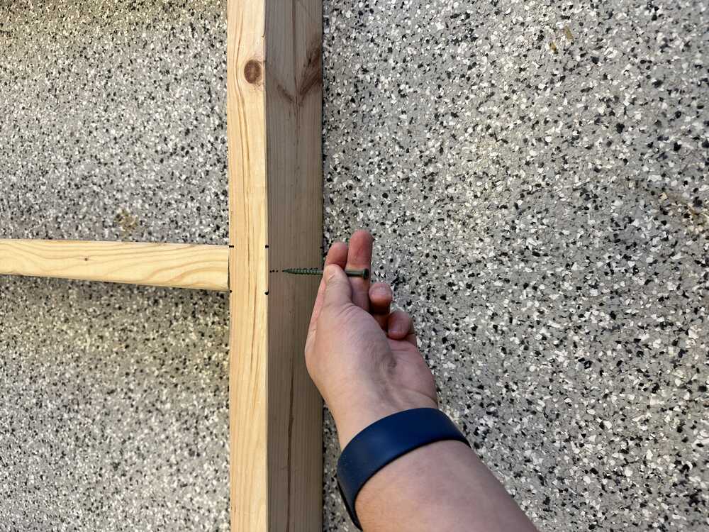
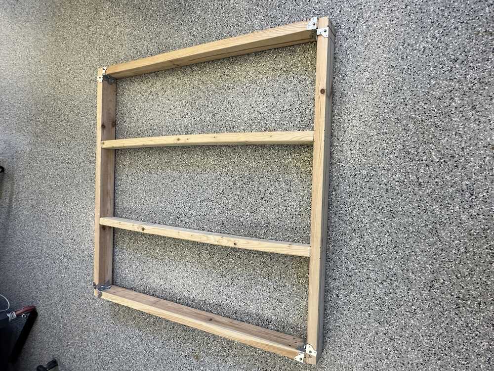 and then secured them using the long decking screws.
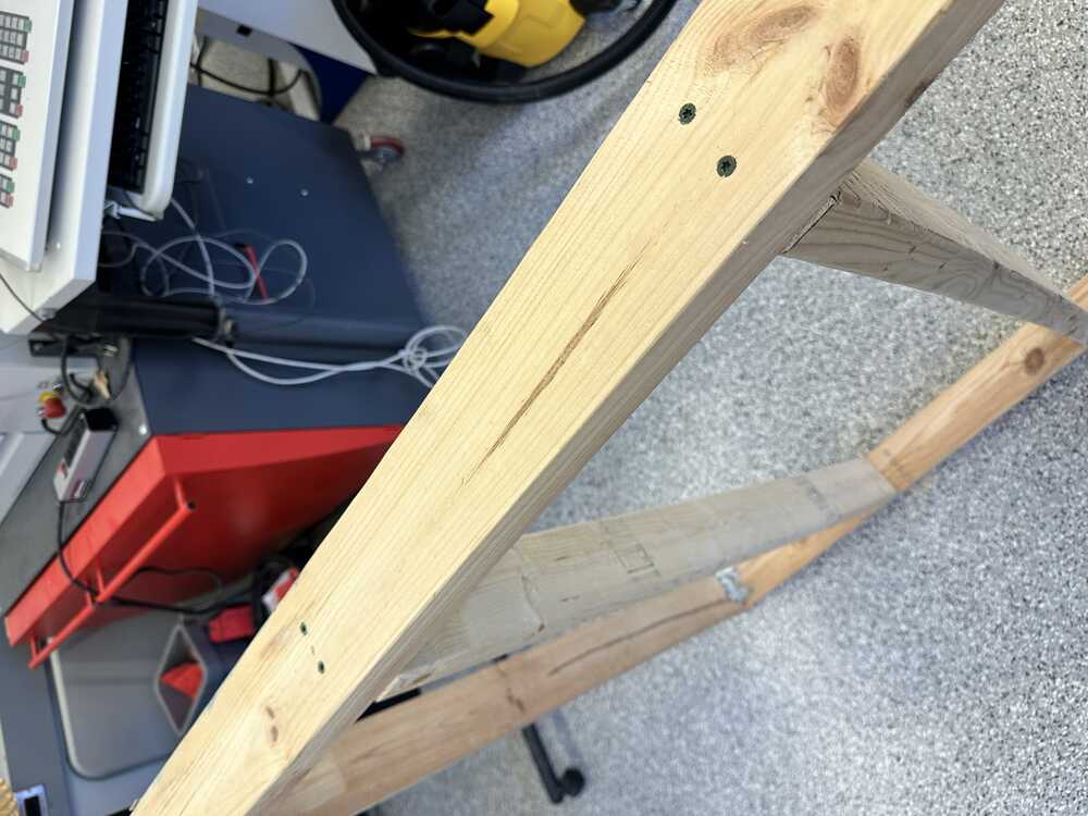
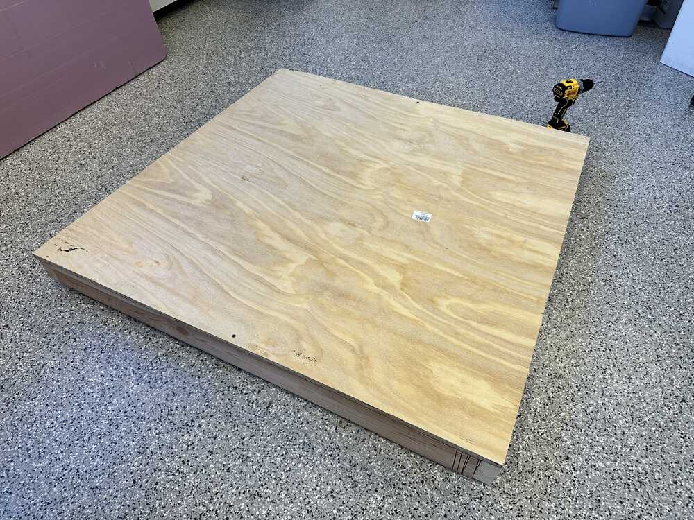
Finally, I used the 1 5/8” screws at roughly regular intervals to attach the plywood to the frame behind it.
Some of the difficulties that I encountered while building:
- The plywood sheet wasn’t actually square: in fact, it was actually 48” by 47 3/4”, and I had to account for the orientation of the piece relative to the plywood on all cuts.
- In addition to this, I had to deal with the well known fact that “2x4”s are actually a bit smaller than their nominal size.
- The 2x4’s were quite warped, which meant that the angles of the cuts and the lengths depended on the final straightness of the pieces.
- The wood would sometimes split/crack when drilling screws in (even decking screws), so I had to drill pilot holes for all screws.
- The corner connectors were a bit hard to bend into a 90deg angle and were a bit crooked.
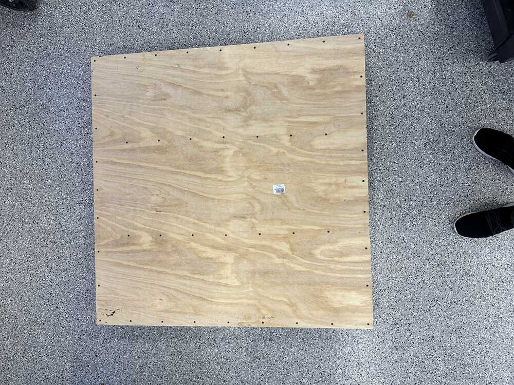
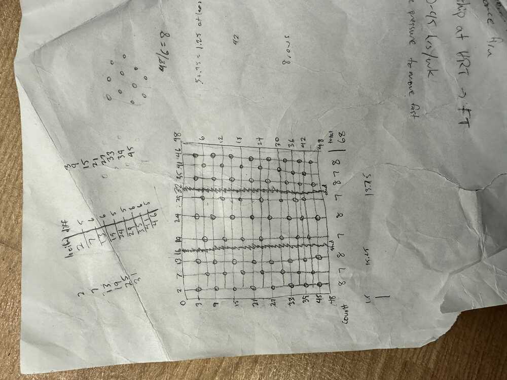
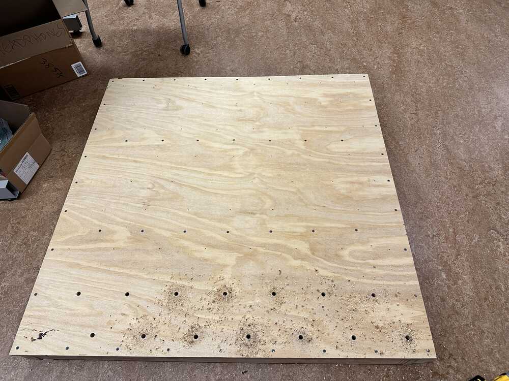
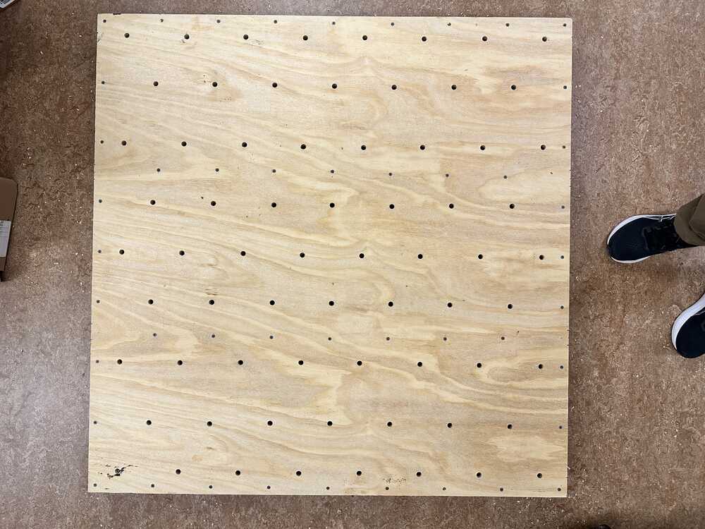
The next step was to put in the holes for the T-nuts. The first step here was to decide on a hole pattern. There are a few commonly used hole patterns, but due to the studs running along the back of the wall, I came up with my own hole pattern that approximated the pattern with each row offset a half spacing from the one above, as follows:
Next, I carefully marked the locations of the holes and drilled them using a drill and a X sized Forstner spade bit. I tried to keep the angle of the hole as perpendicular to the surface as possible by just eyeballing.
The next step was to install the T-nuts. My first attempts involved using a large mallet and trying to hammer the T-nuts into their holes. However, it was difficult to get them to bite into the wood fully with this method.
Dave came up with a better method that also didn’t create a lot of noise. This involved taking advantage of the large compressive forces caused by screwing in a bolt to install the T-nut. Using an allen wrench and a plate to diffuse the forces, I could now install the T-nuts in fully, with a bit of effort.
At this point, I had a wall that I could attach climbing holds to, and they could be easily detached and reattached using just an allen wrench.
March - May
The next steps were:
- Fabricate the holds that will end up on the wall
- Write the firmware for detecting when a hold is used
- Output current hold use via a display
- Integration hell
Fabricating holds
Climbing holds are actually remarkably expensive, and a pack of just a few dozen can cost into the hundreds of dollars. Instead, after reading online, I found that I can make my own holds by 3D printing them.
I found a few examples of climbing hold designs that people have made and put online for free and decided to start with those.
The instructions for printing those holds said that PLA is strong enough to use, but Anthony had his doubts and convinced me to use the stronger PETG filament instead.
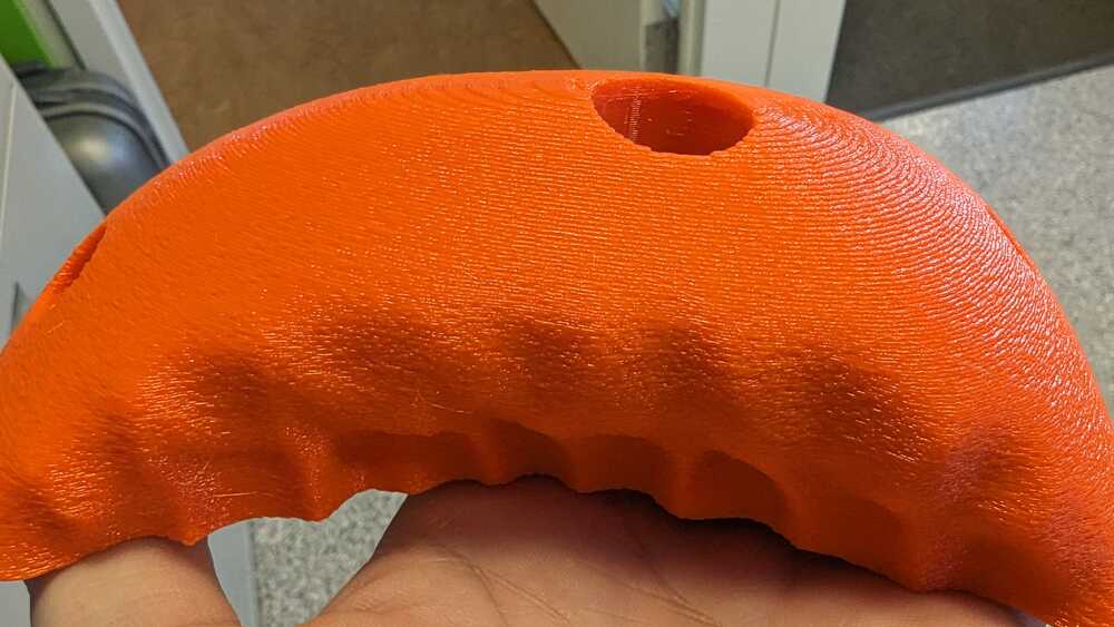
To get a surface tecture that is similar to commerical holds, I used the “fuzzy skin” feature on PrusaSlicer.
The non default settings I used for my first print were: layer height 0.3mm, 40% infill. Fuzzy skin with parameters 0.3mm and 0.3mm. With 6 vertical and horizontal walls.
This run had walls that were textured similarly to a commercial hold, but due to PETG being pretty slippery, I found that I wanted the fuzzy skin to be a bit more fuzzy to better approximate the commerical hold texture.
On the subsequent prints I used: layer height 0.2mm, 40% infill. Fuzzy skin parameters 0.5mm and 0.3mm. With 6 vertical and horizontal walls.
I liked the texture that came out of these prints more and stuck with it for the rest of the holds.
The ones that I ended up using can be found here: Hold 1 Hold 2
One of the ones after being printed looked like:
Hold detection
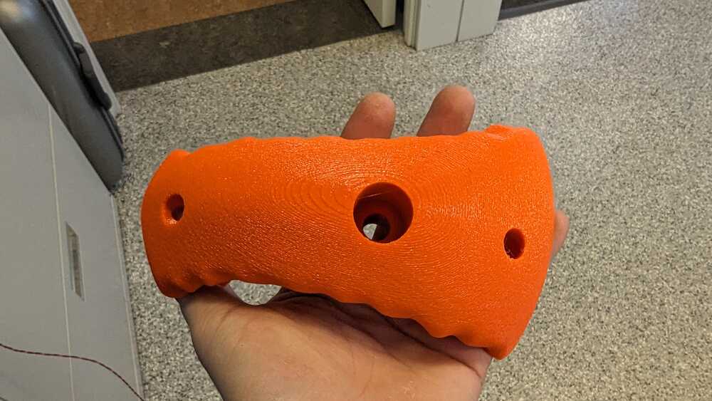
From glancing through Alejandro’s project, I found that there was a simpler way to use capacitive sensing on the ESP32S3 than building a RC circuit and measuring the voltage difference after a fixed duration. I could just use the Arduino touchRead(pin) API, which returned a value corresponding to the capacitance that the pin is detecting. Thus, to measure if a hold is being used, I could connect a pin to the bolt securing the hold to the wall, and compare the current touchRead(pin) value to a baseline value. With some experimentation, I settled on a threshold value for which if the value was higher than the baseline by, then the hold would be considered as being used.
The physical connection between the pin on the board and the hold itself was pretty convenient: each hold is secured to the wall via a bolt, which I could connect to. Moreover, this bolt is centrally located on the hold, and thus is positioned well for detecting if a hand is on it.
Wtih some tweaking of the code and the threshold, I was able to pretty consistently detect whether a hold was being used.
Inter-microcontroller communication
Details about the electronic hardware design can be found in my Networking and Communication writeup
Output via a display
I wanted to mount a display onto the wall which would display the current hold usage. I obtained a spare 2.8” TFT LCD screen from Anthony. I had originally planned to use a display that spoke I2C, but without realizing it, the display that I had was actually one that used SPI.
Instead of making a new board, I decided to just go with the board I have an repurpose some of the pins I had broken out for capacitive sensing, and just use them for SPI. This resulted in less pins available for detecting holds on the first ESP32S3 board.
More details can be found at Interface and Application week
Integration Hell
There’s an annoying thing about projects like this where individual components of the project work totally great by themselves, but just completely freak out when they have to work with other components.
My overall structure of the electronic side of the project is as follows:
A board with three Xiao ESP32S3 Senses communicating via I2C lines built into their shared PCB. The leftmost board is the “controller” and the other two are “followers.” Each follower breaks out 7 pins for tracking up to 7 holds being used and sends the current hold usage information to the controller. The controller is itself responsible for tracking 3 holds, collecting the current hold usage from the followers, and outputting the current hold usage across all three boards to the display. Thus, I can concurrently track if 17 holds are being used.
To measure whether a hold is being used, I wrapped the stripped end of a wire around the bolt securing the hold and connected the other end to the corresponding pin on the ESP32S3.
This all sounds great in theory, and at this point, I had each individual component working on its own. However, I ran into many more issues when I started putting the pieces together.
For example, the capactive sensing worked great when only one ESP32S3 was measuring at a time, and the wires connecting to the bolts were relativelty short. However, when I connected faraway holds with long wires, there seemed to be a decent amount of noise in the measurement, and I was getting frequent false positives. I made a slightly hacky change that removed most of the false positives by changing the code to count a hold as “in use” only if both of the most recent two touchRead(pin) measurements were above the threshold. Thus, a false positive would require two consecutive high measurements, which was less likely. I was never able to fully remove the false positives, unfortunately, which I suspect is due to the longer lengths of wire used in the final project, which were more susceptible to noise and other signals.
In Action!
Here is an example of what the final project looks like in action!
Materials list and costs
- 1x 4’x4’x23/32” sheet of BC plywood (I couldn’t find ACX plywood) ($38.69)
- 1x Box of 3” decking screws for the frame ($11.47)
- 4x 80 degree corner connectors ($5.52)
- 1x Box of #8 x 1 5/8” screws ($10.47)
- 1x Box of #9 x 1.5 that fit the corner connector holes (14.24)
- 3x 3/8”-16 2” socket head bolts 10pc ($29.97)
- 1x 3/8”-16 T-Nuts (100 Pack) ($20.99)
- 3x Xiao ESP32S3 ($22.47)
- Some amount of PLA and PETG ($10?)
- Some amount of wires ($1?)
The total comes to around $160, which is quite cost efficient, especially considering that I didn’t end up using most of the screws and bolts that I bought.