HTMA Week 5: Nixies and VFDs
Published: 2023-10-10Nixies and VFDs
During this week, I remembered that I had always wanted to build a nixie watch, or at least a nixie clock. Something like this:

So I decided to pivot my final project to doing just that. I’ll spare the details of my research into nixie tubes for a separate page dedicated to the final project, here are the important bits:
- Nixie tubes use 180V, which surpasses the 50V threshold for the class.
- I’m looking at using IN-17 tubes for their small size and closeness to the reference image.
- These require
- No more than 170V to strike
- 120V-170V to maintain
- 1.5mA current
- These require
- I’m looking at using IN-17 tubes for their small size and closeness to the reference image.
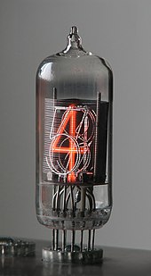
A Nixie Tube
- An alternative is to use Vacuum Fluorescent Display(VFD) Tubes, which only require 12V to 30V to operate, but has a slightly different mode of operation than nixie tubes.
- I’ve purchased 6 IV-22 VFD Tubes off of eBay for $36.44.
- These require
- 1V-1.32V for the filament
- 100mA nominal current consumption
- 22V-30V for the grid
- 6-10mA grid current
- 22V-30V for the anode segments
- 4mA of anode segment current
- 1V-1.32V for the filament
- These require
- I’ve purchased 6 IV-22 VFD Tubes off of eBay for $36.44.
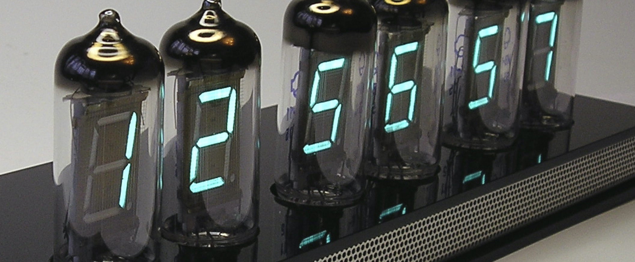
Vacuum Fluorescent Display Tubes
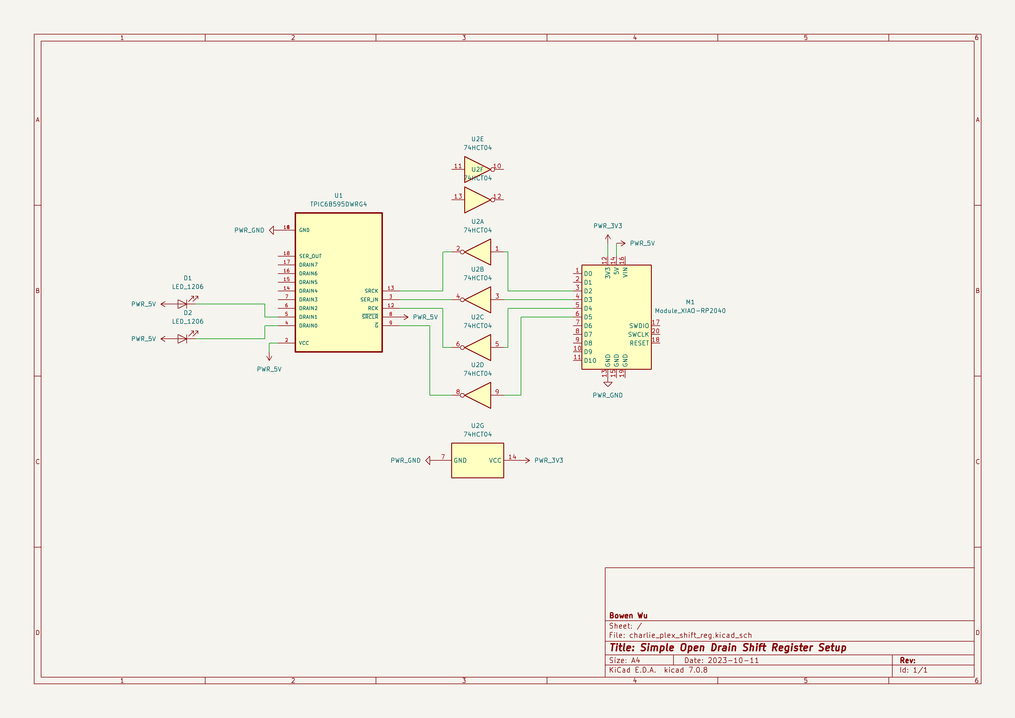
- To minimize re-doing work when I eventually switch to nixie tubes, I’ll try to design the PCB as if we’re using nixies where possible.
- This means we’re using the TPIC6B595 Power Logic Shift Register instead of regular shift registers.
- These ICs run on 5V logic, so we need to use the 74HCT04 in order to convert 3.3V from the RP2040 IO pins to 5V.
- We pull the SRCLR pin high to 5V because we won’t have to clear the registers, this also saves one pin.
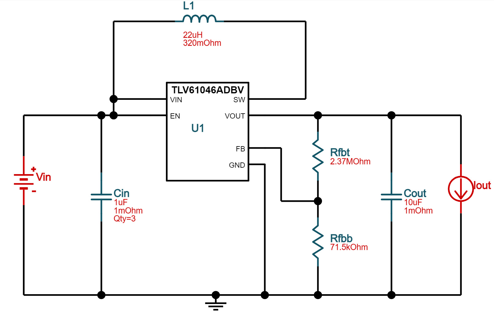
- VFDs still need at most 30V to power the grid and anodes, so we make use of the TLV61046A for its small footprint and efficiency.
- We can eventually use this as an input for a boost circuit to generate the needed 170V.
- To program for 28V output with maximum 6mA output, we need the following setup- However, we won't implement this in the schematic for this week. We'll use it for the next prototype when we get the VFD tubes in hand.
- This means we’re using the TPIC6B595 Power Logic Shift Register instead of regular shift registers.
For now, we’ll go with the following schematic to control 2 LED diodes.