HTMA Final Project: VFD Clock
Published: 2023-09-03Strobing of the tubes is only in video, not visible in real life
Locally hosted version in case Youtube doesn’t work:
Concept
Concept and product by someone else, not mine
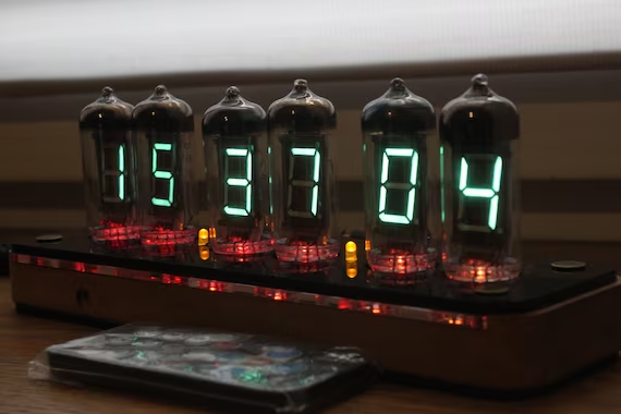
For my final project, I decided to take my week 5 project one step further and make a clock display out of those Vacuum Fluorescent Display (VFD) Tubes. I decided to model my clock after the radio from the video game Portal, but replace the FM frequency display with VFD tubes:
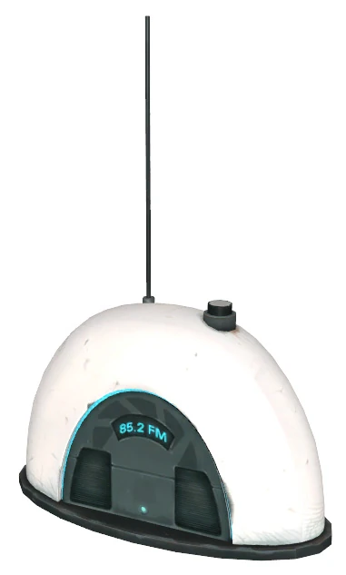
From Portal(2007)
While having a clock is the main goal, I’d also like to make it a functional radio. Meaning that it will have a working stereo speaker system, complete with a tunable FM Radio receiver. So, the minimum viable product goals for this project include:
- 3D printed housing that models after the game inspiration
- 4 VFD tubes
- This also means a 27V power supply to power them
- Ability to display the current time of day
Stretch goals include:
- Working stereo speaker system
- Working tunable FM Radio Receiver
This is by no means a novel project, since designing VFD clocks is something commonly done by electronic hobbyists, and plenty of makers who like video games have made replicas of the Portal radio. While the housing design will be taken directly from the game, I will still be responsible for modifying it to fit 4 VFD tubes, as well as the electronics and software for driving the tubes to display the current time.
Hardware
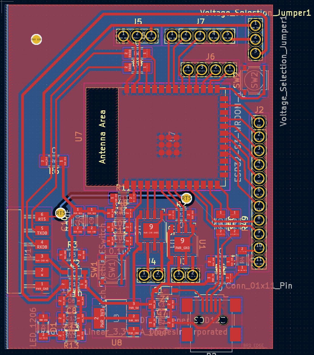
Main Board
This board will contain the ESP32-S3 microcontroller provided by Anthony, with its pins broken out to connect to other peripherals, such as the display board, rotary encoders, buttons, and speakers.
Power
The ESP32-S3 requires 3v3, but USB connections only provides 5V, so we will need a 5V to 3V3 voltage regulator. I chose the 1A variant of the AZ1117I from the EECS section stock. I included a diode on the 3v3 output to visually indicate if the ESP32 is powered or not.
ESP32
As for properly routing power and USB data to the ESP32, I modeled my schematic after the schematic for the ESP32-S3 Devkit. Because only Mini-USB’s pins were millable with a 1/64 end-mill, I had to use that over Micro-USB and USB-C.
Peripherals
I broke out pins for the following peripherals:
- 2 Speakers
- Driven by two [TB67H451FNG] H-Bridges
- Photo-transistor measurement
- Display board
- 4 VFD enable pins
- Shift Register inputs
- 27V boost converter enable pin
- Rotary Encoder
- I purchased these rotary encoders with knobs from Amazon for $9
- With 5V/3V3 selection jumpers
- RGB Button
- I purchased this button from Adafruit for $15.94
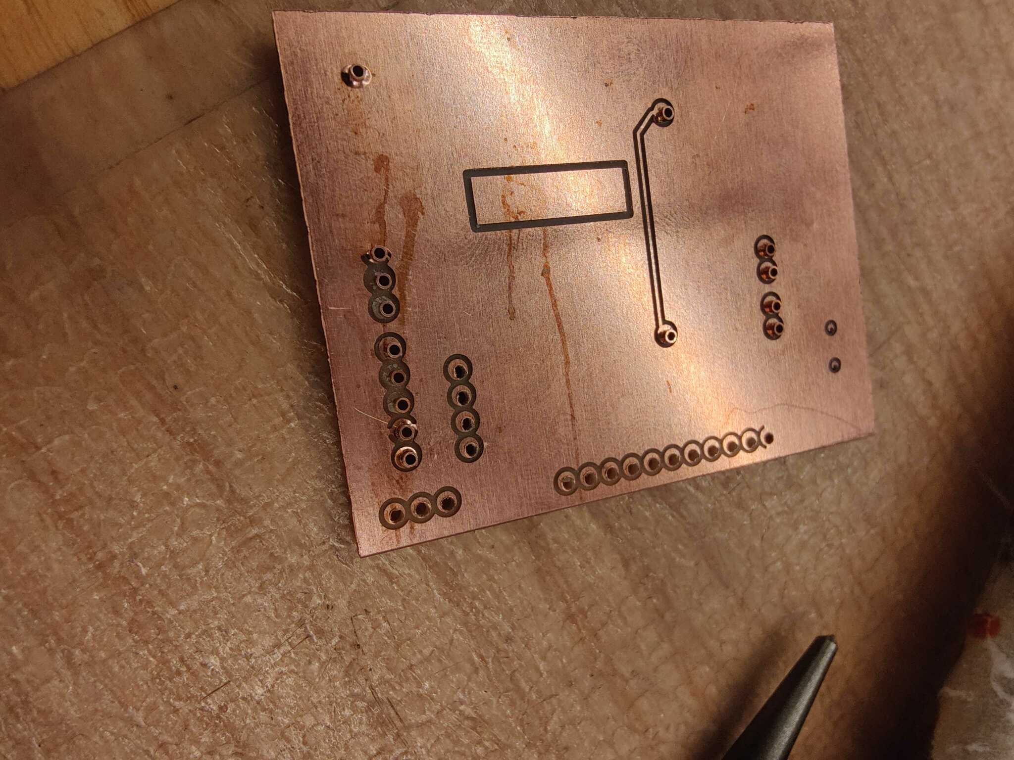
Vias
Because I’m milling the board, I’d have to manually fill the vias with rivets. I chose to make my via holes have a diameter of 1.5mm to be large enough to fit header pins into.

Bit small to read, should right click and open it
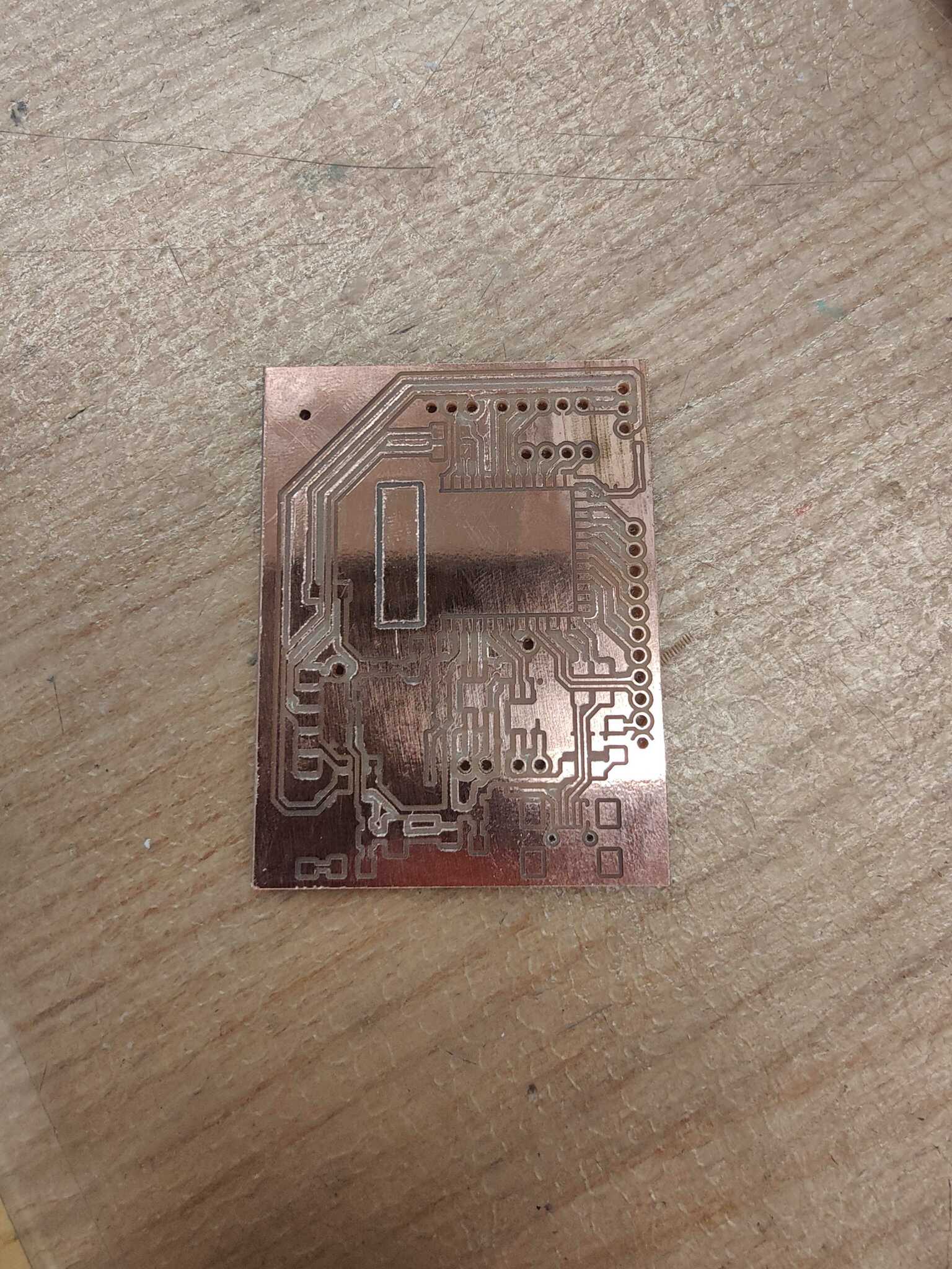
Manufacturing
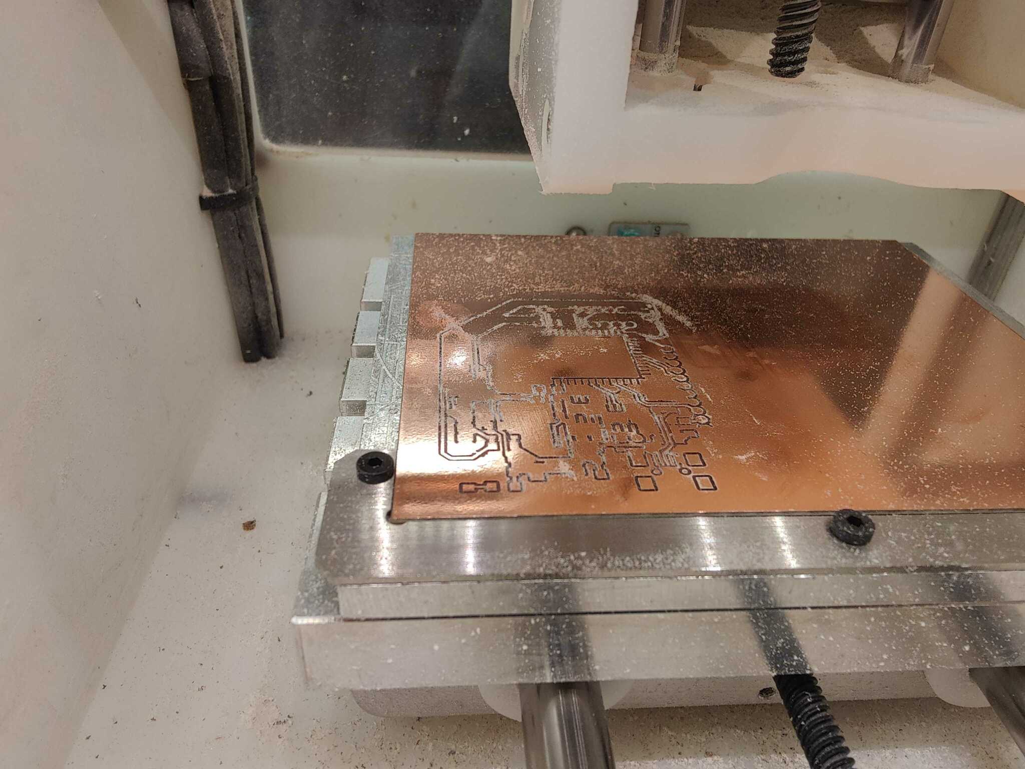
This board required 1/32 and 1/64 end-mills, and took about 2 hours to mill.
Once milled, I had to manually fill the 1.5mm via holes with rivets, putting each through the hole then using a hammer and a set of rivet tools made specifically to flatten out the other size to secure it.
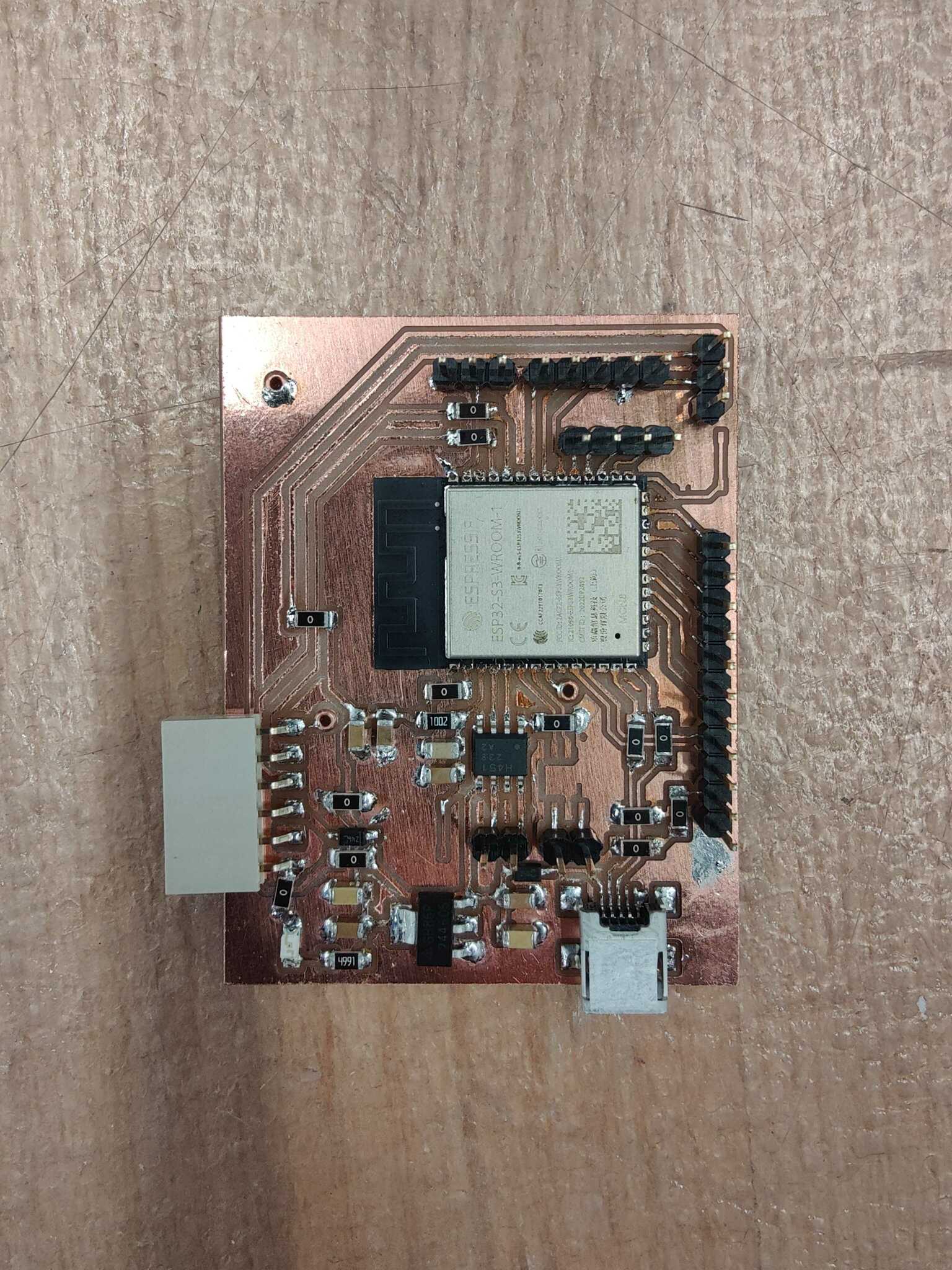
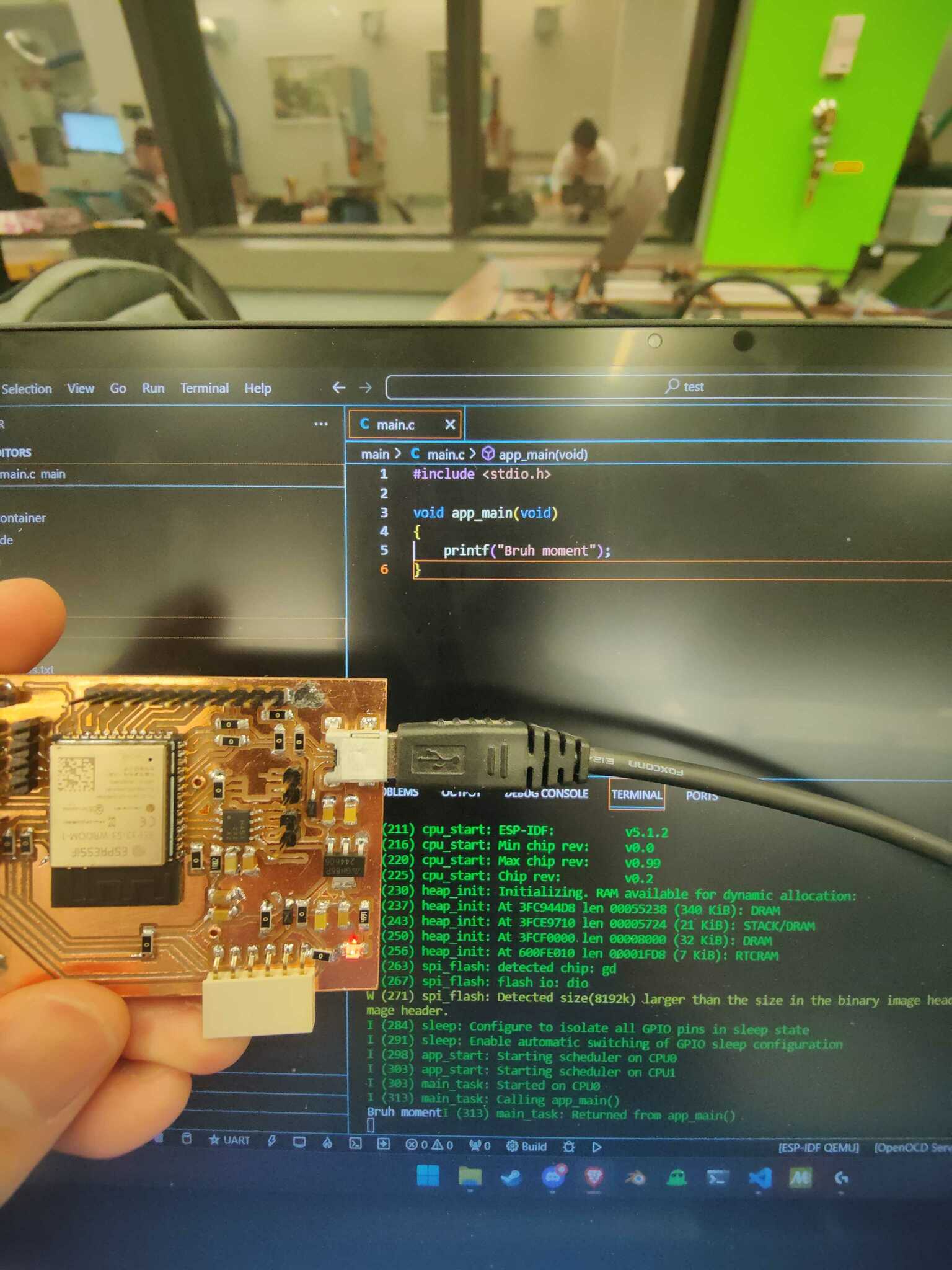
Once the board vias are filled with rivets, I finally soldered every component to it and tested it out with the ESP32’s IoT Development Framework (IDF); Specifically, I followed the instructions for their VSCode extension. I configured the project to target esp32s3, and to flash over USB built-in JTAG since we have Micro-USB connected. I was then able to successfully program the chip and have it print to my terminal over UART.
Display
For the display, I will use 4 of the 6 VFD tubes that I bought from eBay($36.44 at the time) for week 6 to show the hour/minute or minute/second. However, I won’t simply copy the circuity from week 6, but will instead re-design it to be more power efficient, and will make use of multiplexing to drive all 4 VFDs. The details of this can be found in my week 10 entry, though here’s a summary:
- There are now 8 high-side switches, driving the 8 anode pins on each of the 4 VFD displays.
- High-side switching uses less power than week 6’s design, since 27V won’t be connected to a load at all times.
- The ESP32 also controls 4 high-side switches that drives the grid pins of the VFD, which controls whether it is on or not.
- So I will only turn on one tube at a time with the correct anodes being lit for each tube, but scan through them at a high frequency to make it seem like every tube is always on.
- Since we’re using multiplexing, only one shift register is required to control the anode pins.
- This shift register can be interfaced over SPI because of how similarly they operate, though it is not explicitly an SPI device.
While I initially asked Anthony to order a PCB version of this board, it unfortunately did not arrive until demo day. When I realized that it wasn’t going to arrive on time I had to mill it myself instead.
Power
As for the 27V power supply needed for the VFD tubes, I will reuse the same TLV61046A circuit that I designed for week 6. Since I am only keeping one tube lit at a time, we only need the 27V rail to provide enough power for one tube.
Schematic and PCB
I’ve also decided to separate the board with the VFD tubes from the main board. It will receive logic input for multiplexing from the main board, along with 5v and 3v3, and generate 27V from the 5V input. Here’s the schematic, layout, and board from week 10.

Bit small to read, should right click and open it
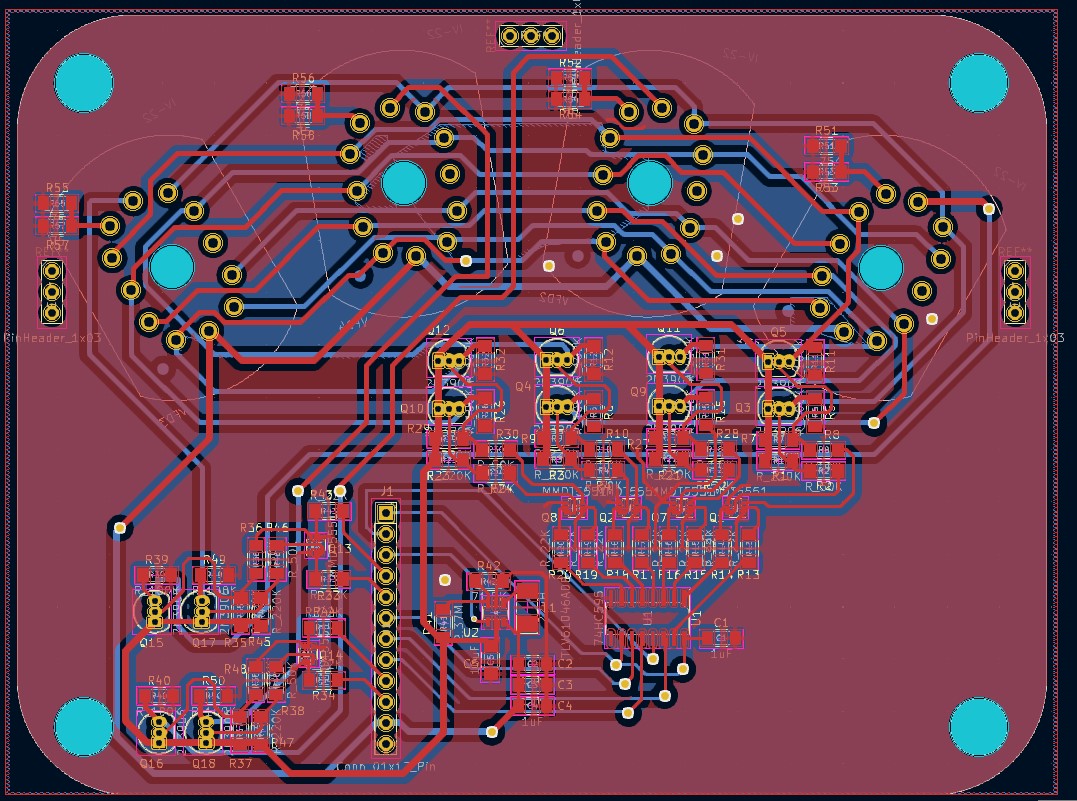
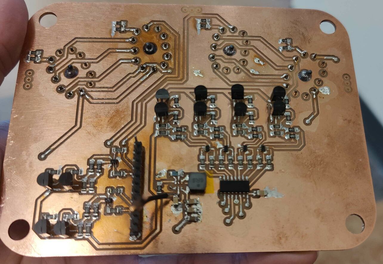
Front of the PCB
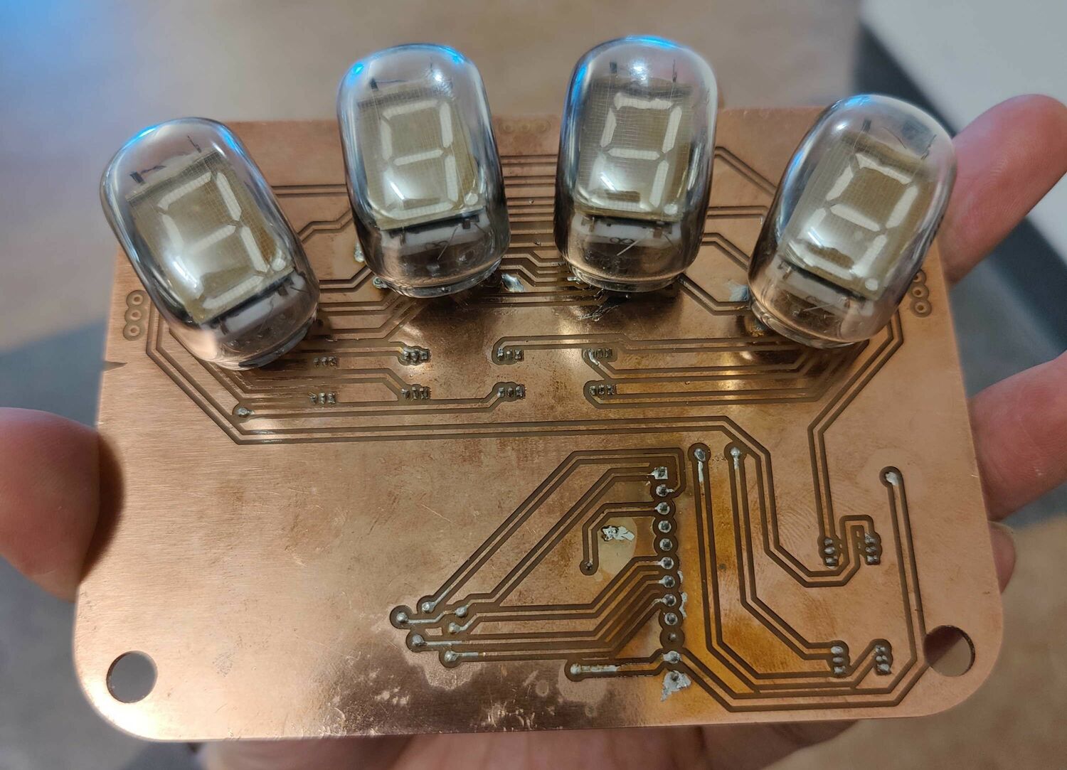
The VFD tubes go on the back
Power Issues
27V
Unfortunately, when I tried the display board out, it did not work as I expected. I noticed that the shift-register couldn’t properly output 3.3V when I turned on the 27V boost converter, and therefore couldn’t turn on any segments on the display. After a bunch of debugging and backtracing, I noticed this:
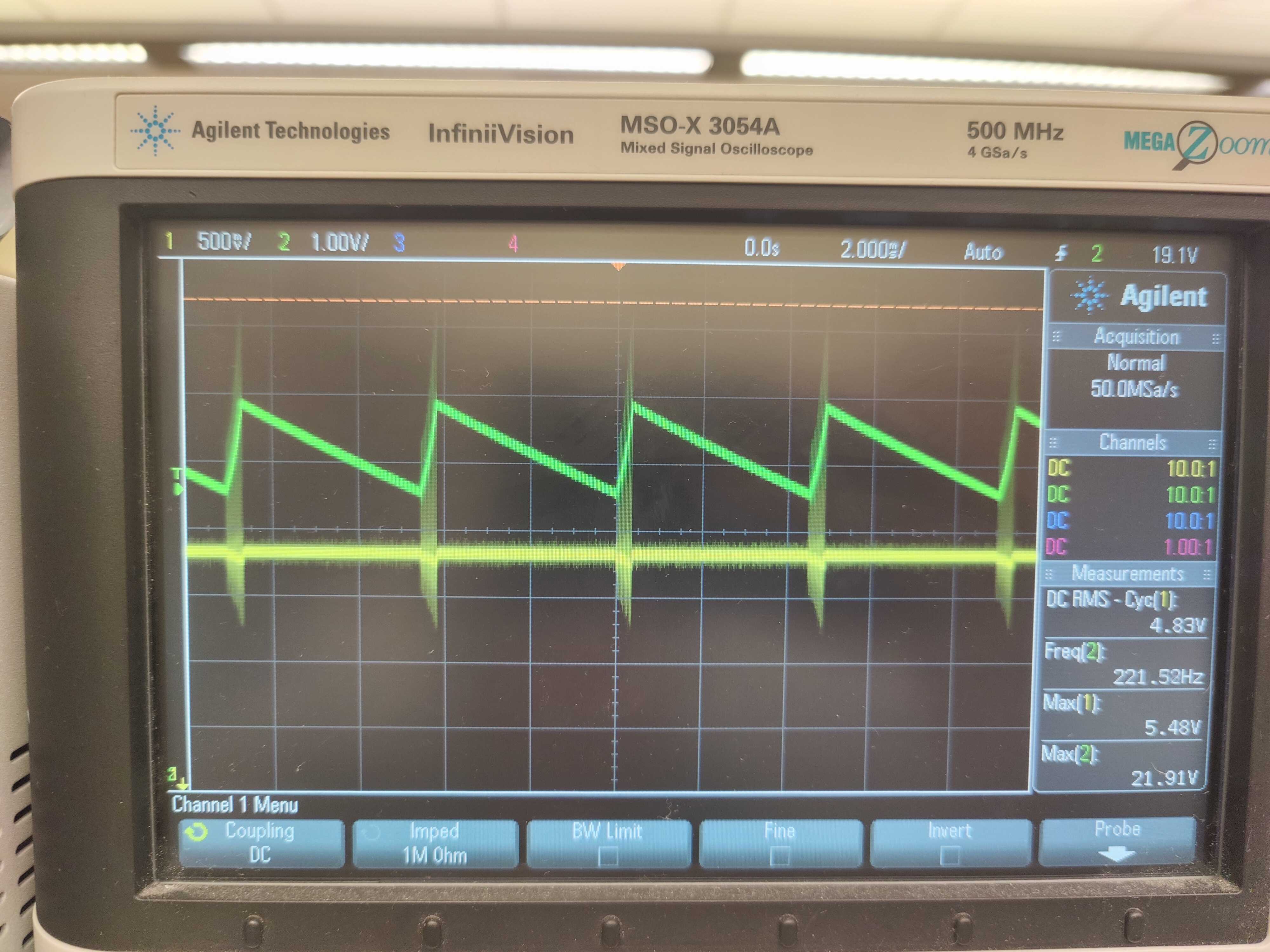
Green: 27 V, Yellow: 5V
The TLV61046A generates 27V by outputting a PWM wave around 27V, however when the voltage is increasing, 5V gets distorted. This causes the 3.3V rail to also be distorted, which interferes with the SN74HC595’s ability to properly output signals.
I tried various things to fix this, like adding additional capacitor at the 5V input, but none of them helped.
For the sake of time and getting a semi-working final project, I followed Anthony’s advice and used an external programmable power supply to provide 27V.
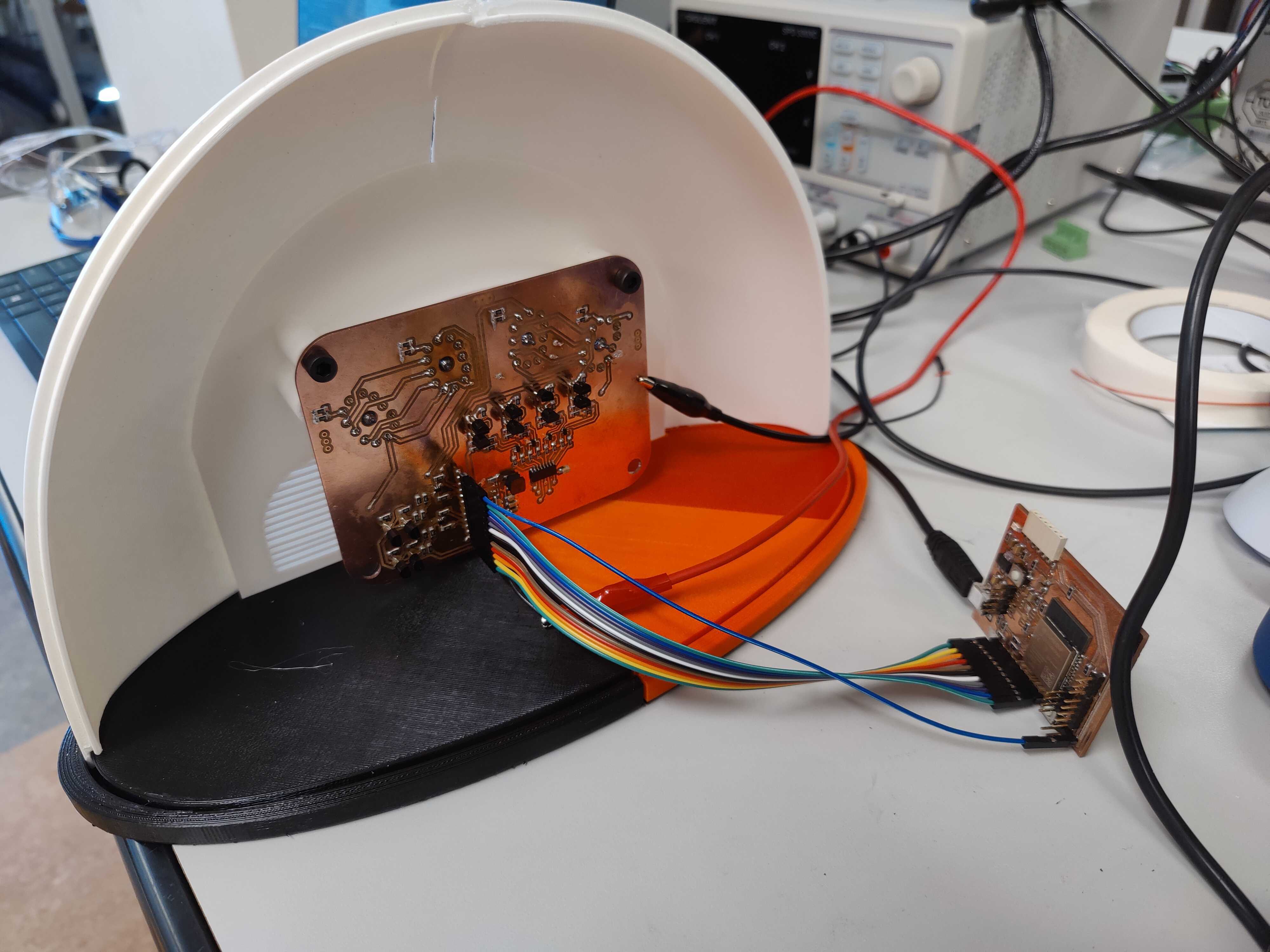
All circuits assembled in the housing with external 27V
Accidental Capacitive Sensing
For completely unknown reasons, I’ve accidentally created a circuit that has capacitive sensing, and found that it would turn off if I put my hand close to the circuits.
Later on, the behavior was inverted. After a minute or two of turning on the device, the tubes would flicker out, and only turn on if I put my hands near the wires.
Housing
The housing will be designed after the in-game model. I downloaded the in-game model and imported it to Fusion 360 as reference.
CAD
VFD Tube Reference
I measured the VFD tubes I have and created a 32x22x28(mm) bounding box of the tube to model my housing after.
Print Area
Something I realized early on was that the housing would not fit on the prusa’s print area, so I’d have to print them in parts then re-assemble them. Specifically, the shell in 4 parts, and the base in 2 parts.
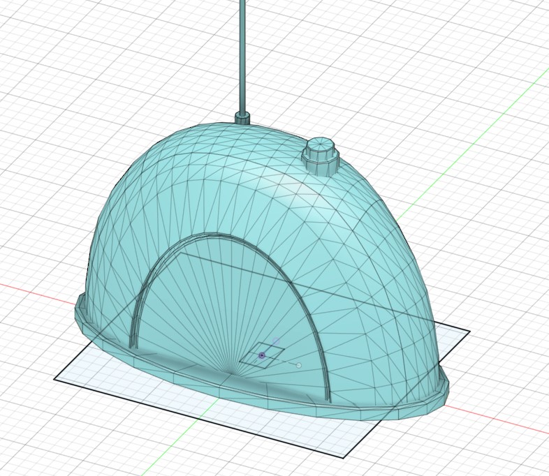
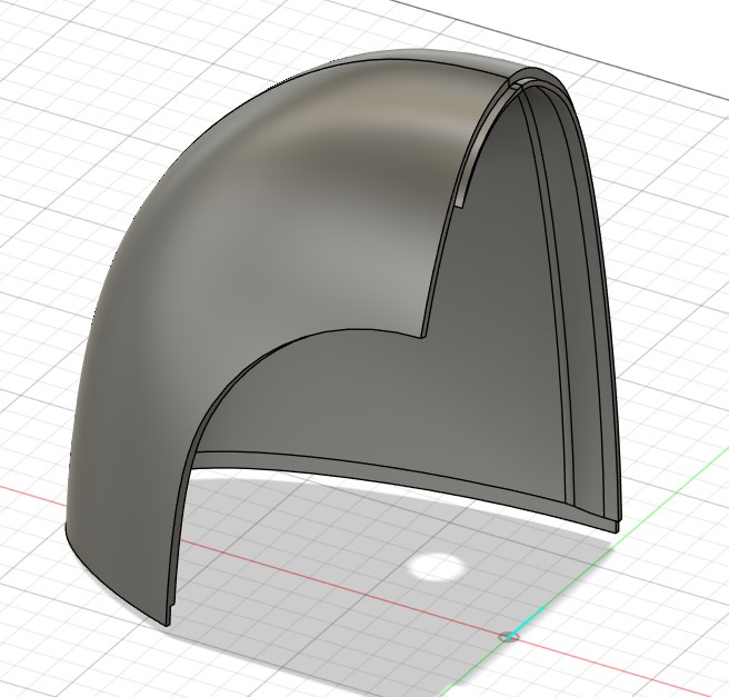
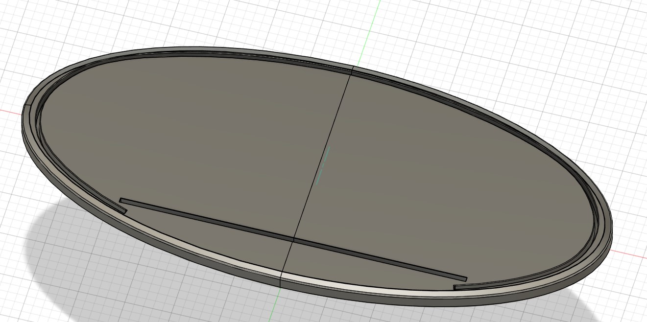
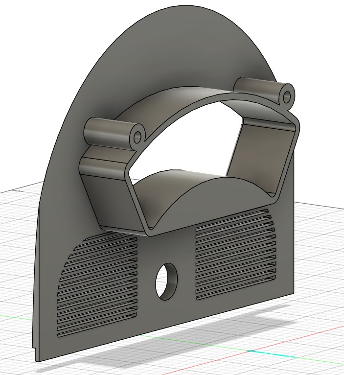
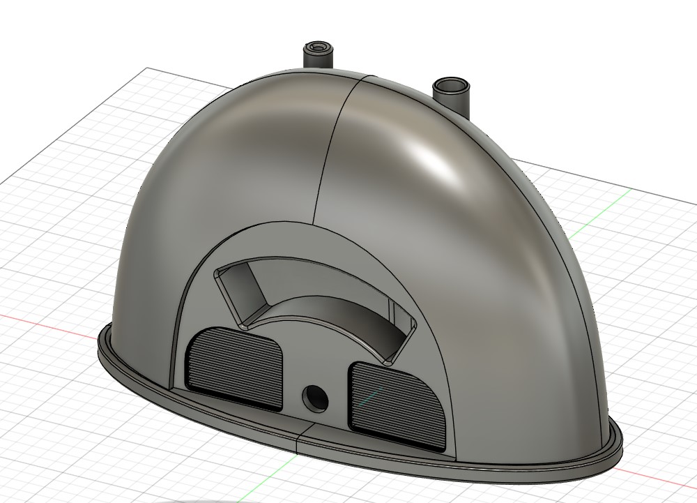
Shell and Base
I then modeled the shell and base of the housing, with press-fit cutouts at the base, and lips between each section of the shell to help them align.
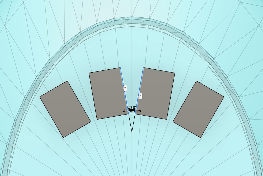
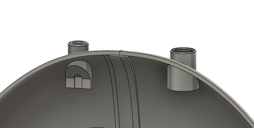
Front Plate
For the front plate that will actually contain the VFD tubes, I made a cutout for the four VFD tubes. To be game accurate, I also added speaker grills to both sides, and a hole for a button in the lower middle.
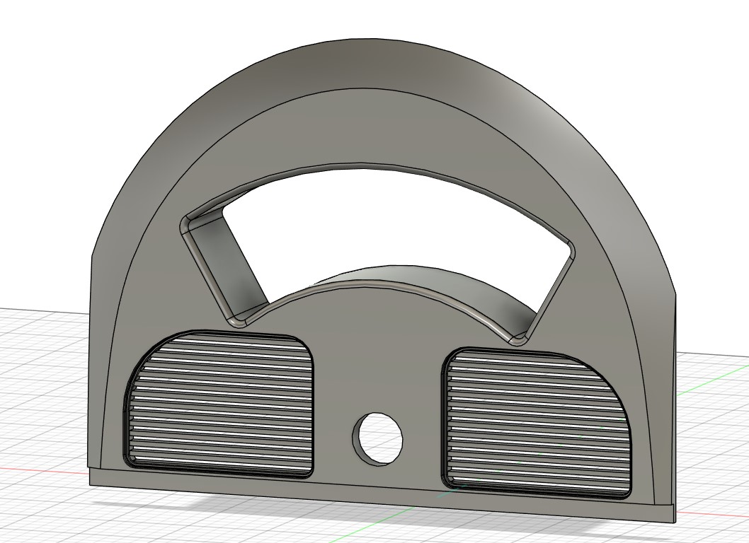
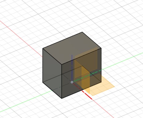
To make sure the VFD tubes sits at a good distance in its cutout and not protrude out, I made a bounding box of my circuit board. I export the display board’s cutout as a .dxf file, imported it to Fusion 360, then extruded to the thickness I measured on the assembled board.
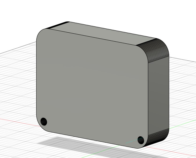
Display board bounding box
Aligned the bounding box to the front of the front plate
With this bounding box, I then made an extrusion from the cutout with holes sized to 5M screws to mount the PCB
Backside where the pcb will be mounted
Antenna and Rotary Encoder
Finally, I modeled housing to hold a radio antenna and rotary encoder, unfortunately these did not get printed in time.
Antenna and Rotary Encoder, left and right
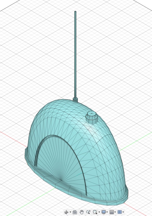
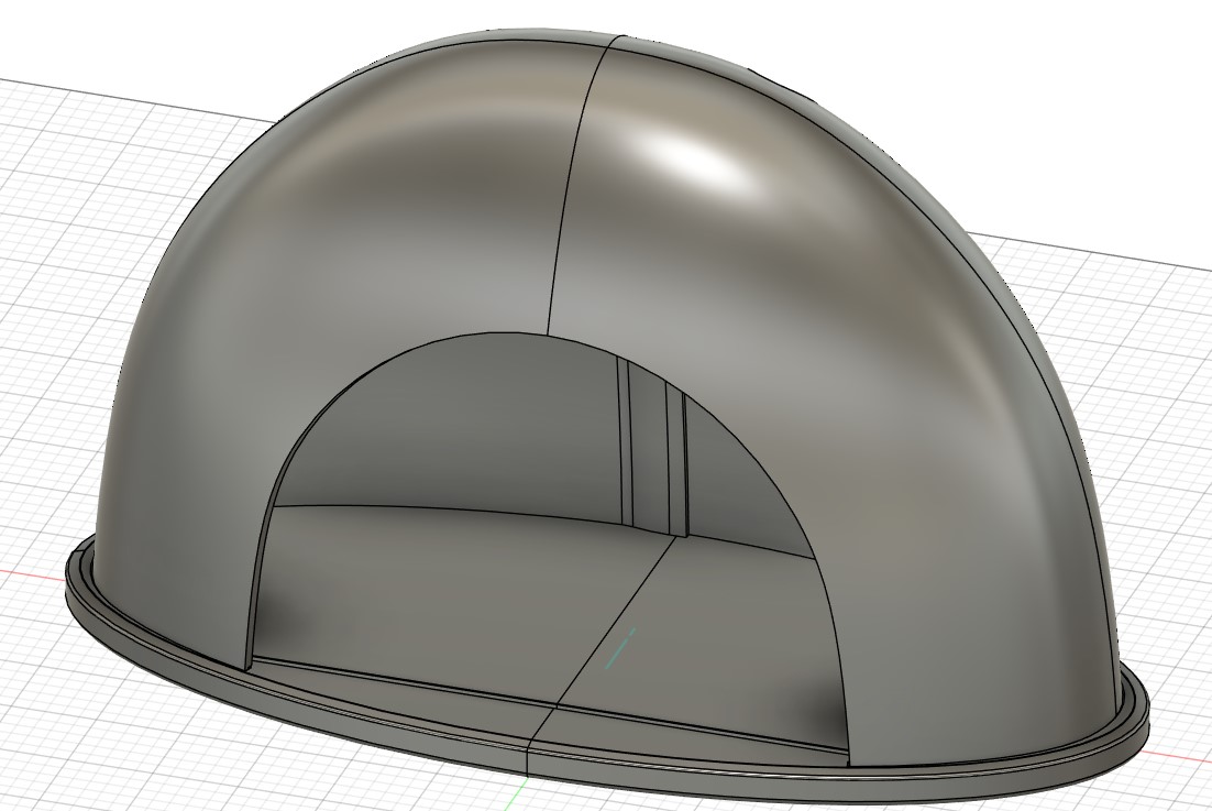
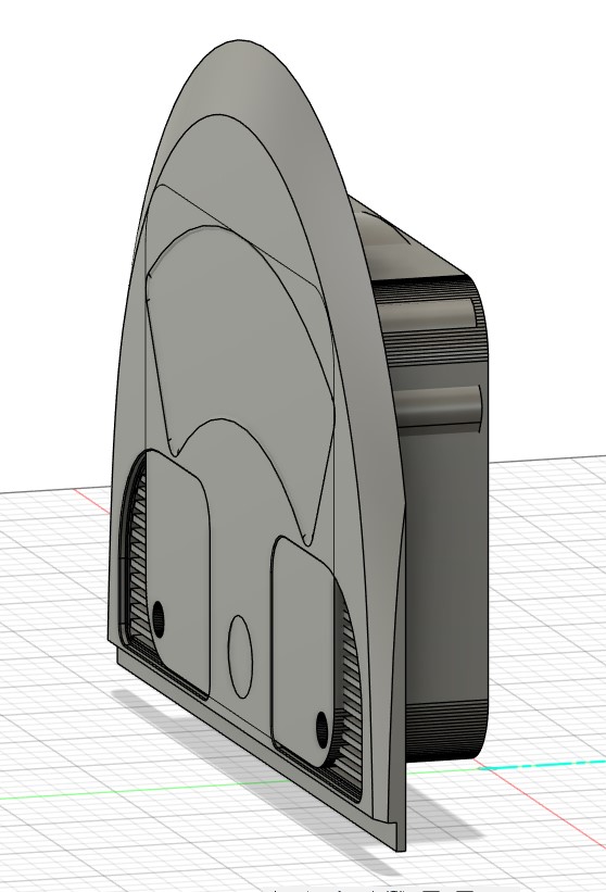
Final CAD
Altogether, the final CAD looks like this
Printing
Because I was short on time, I had to print these parts using 0.3mm heights with about 10-15% infill. Even so, each shell piece took 8 hours, and each base piece took ~3 hours.
I couldn’t be picky about the printer that I used either, so I printed these parts using every printer that the EECS section had available: the Prusas, EDSs, and Stratasys.
This also meant that whatever color filament we had available I had to make do. This results in one of the shell pieces being black, and one of the base pieces being black/orange/red as the black and orange filaments ran out.
Front plate being printed, but in white instead of grey because of material constraints
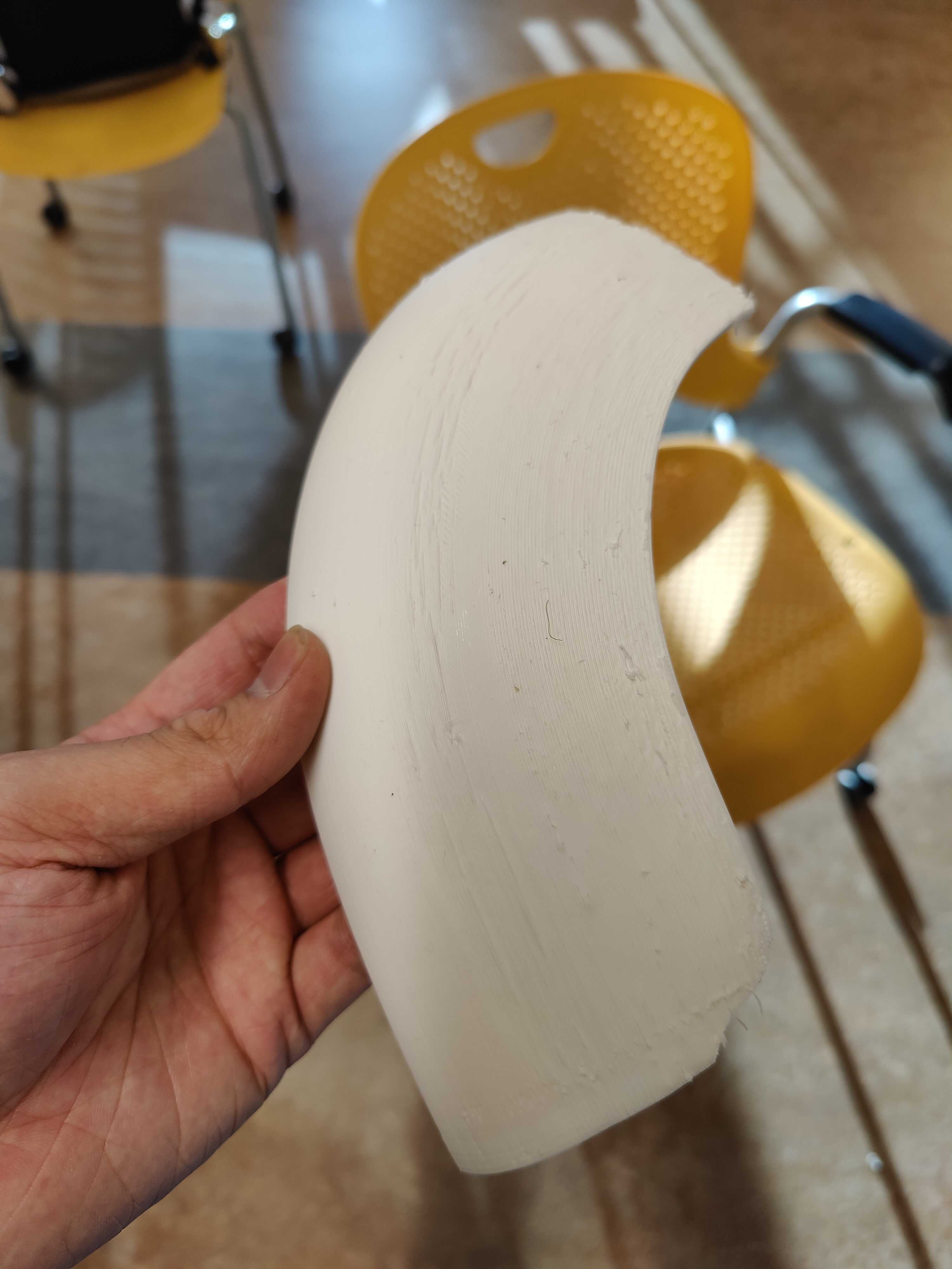
One of the printed shell
I was pleasantly surprised how well the press fit holes I made worked. In CAD, I made them have a slight taper outwards near the surface to help the shells and plate fit in. However, I still had to use a combination of superglue and hot glue to secure the two base pieces together, and to make the shells fit tightly with each other.
Half assembled with the display board.
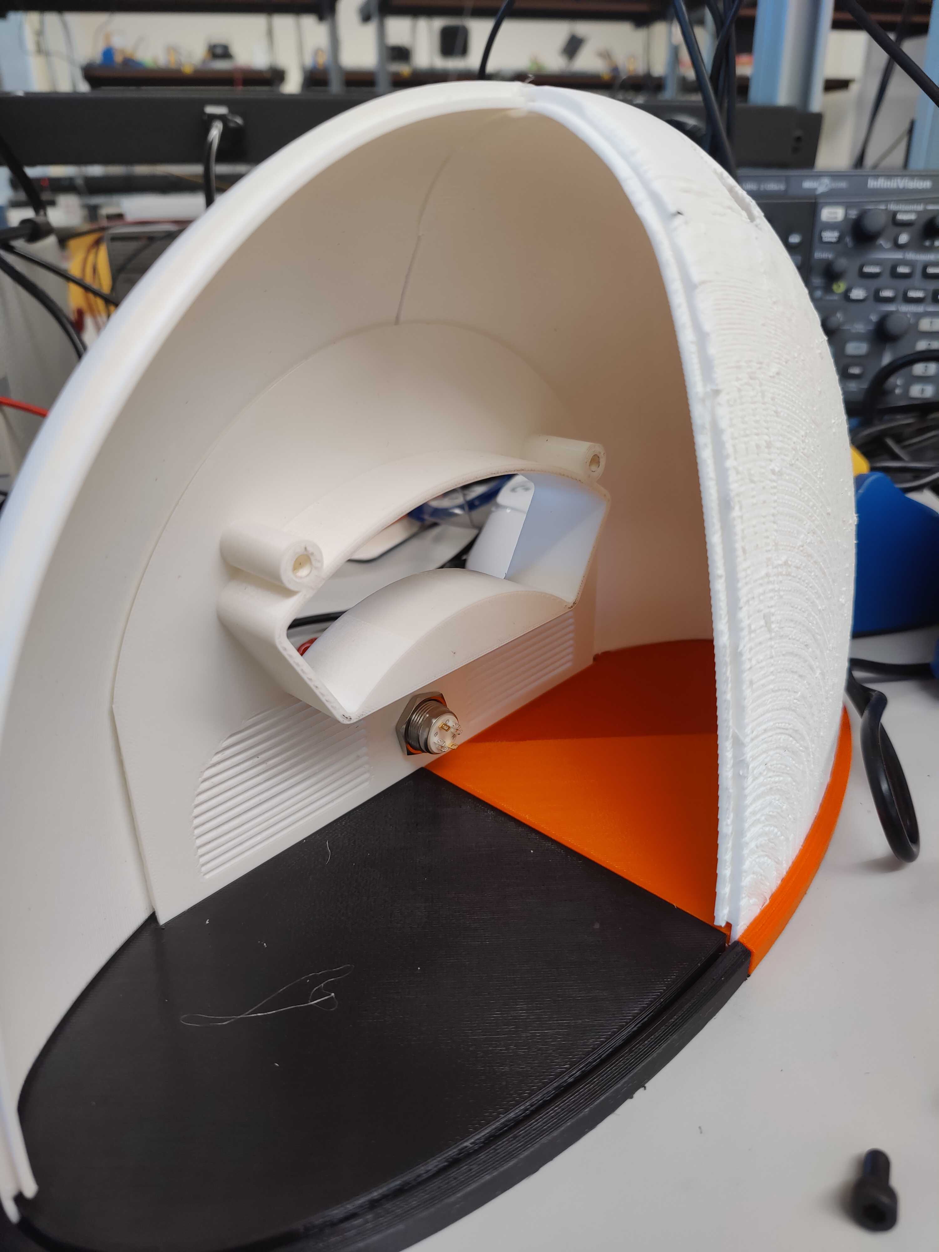
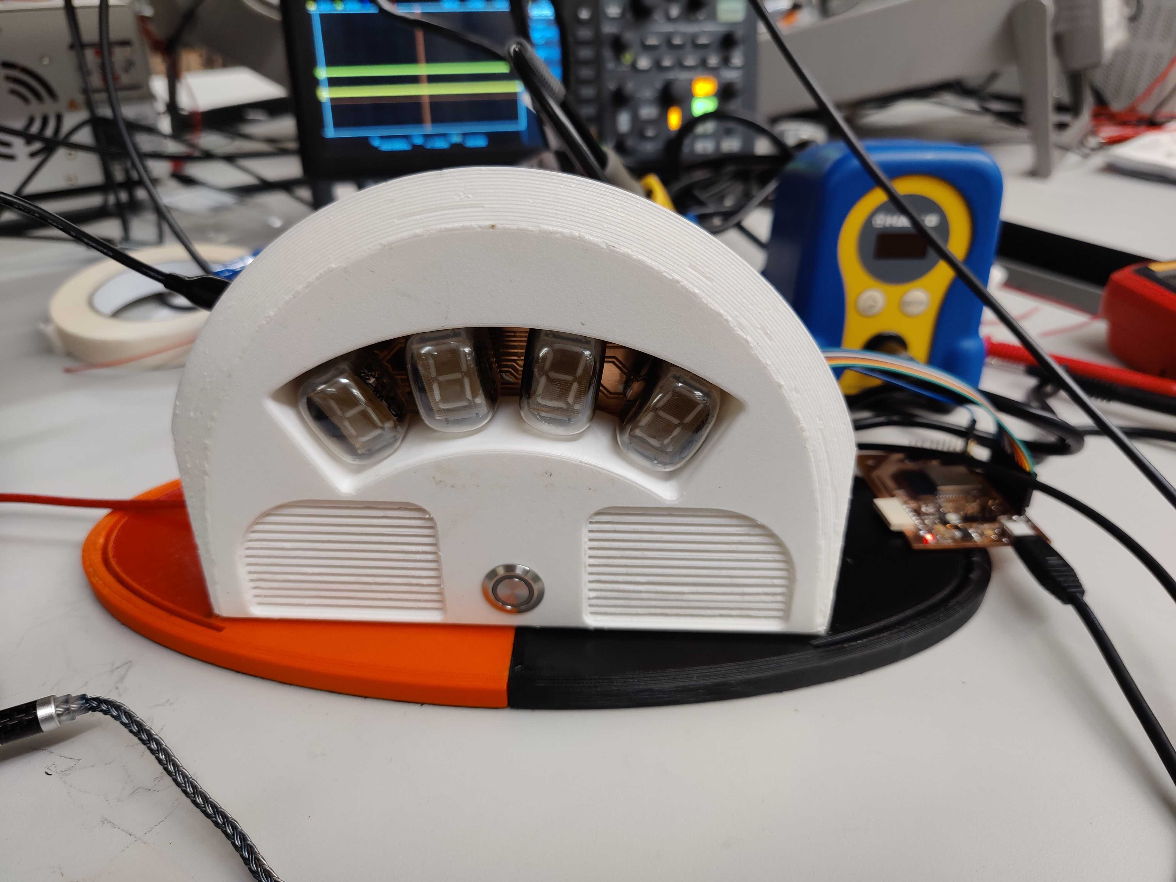
Fully assembly without PCB and one of the shells
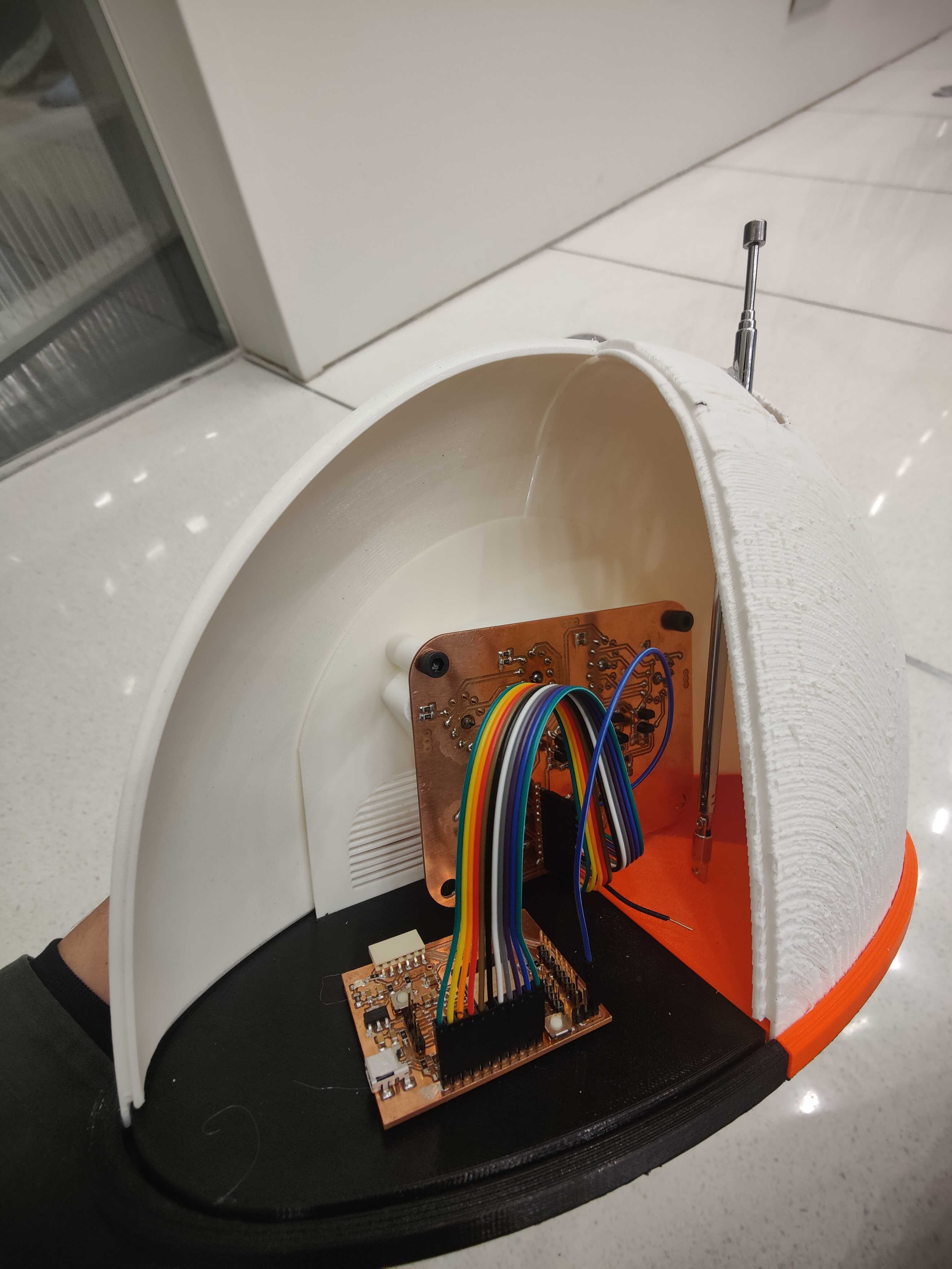
Fully assembly with main board and display board, with decorative antenna
Software
I’ve covered the software needed to operate the multiplexed tube in week 10 and how to retrieve time from the internet in week 11, refer to those for implementation details.
There is one bug that was not noted in week 10. If I left the program to run long enough, eventually it will break. I have no idea what the cause of it is, but it has to do with the functions that I run from the alarm callback function. It seems that I must search for another solution to operate the multiplexed tubes in the next revision.
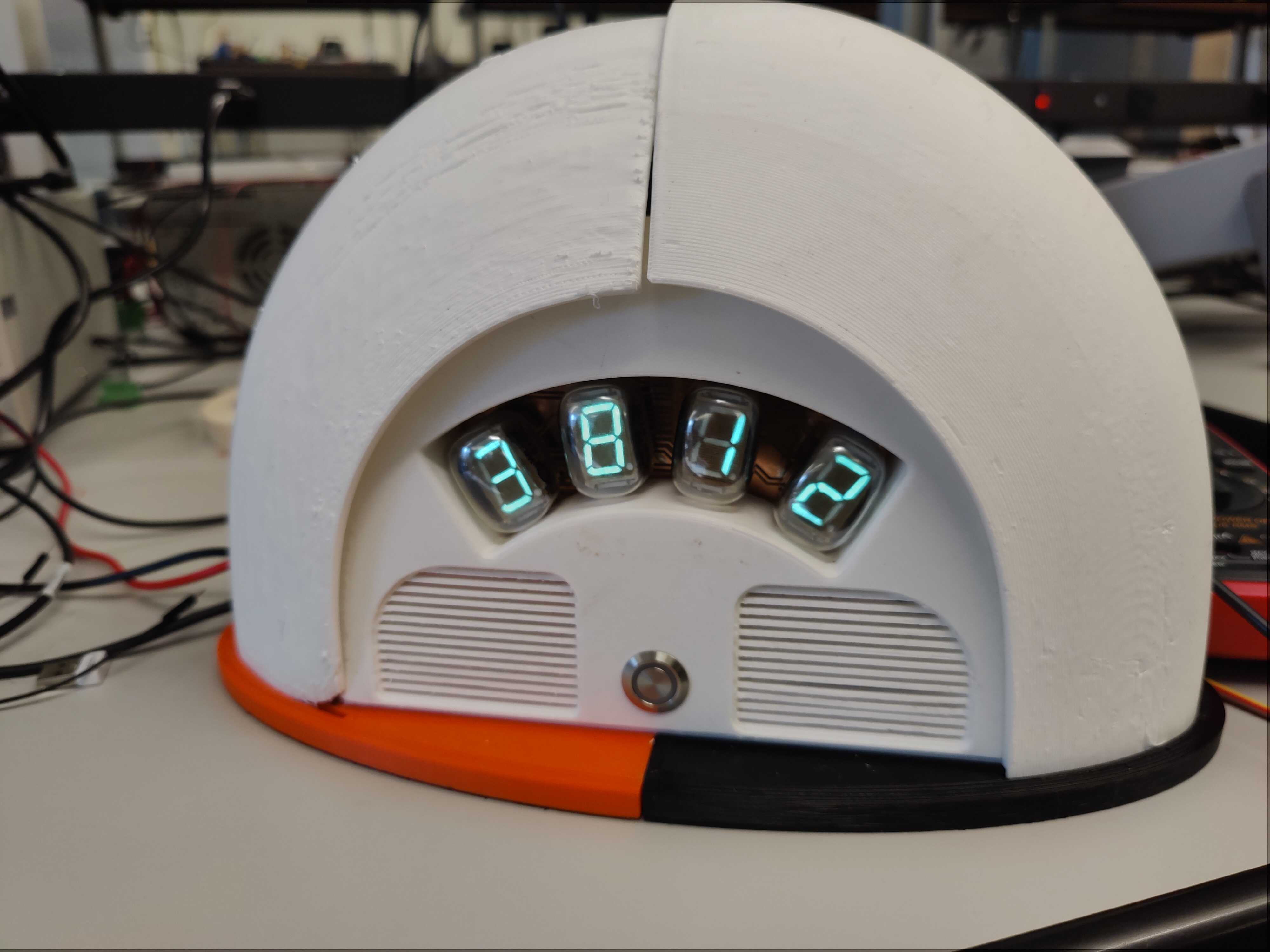
Final Product
In the end, I have a clock that sort of works. It needs an internet connection to retrieve time, but otherwise will start counting from 0. It needs an external power supply hooked up to its 27V rail, but otherwise will not work at all. I also did not have had time to even begin working on any of my stretch goals, unfortunately. However, I will continue to work on this project in my spare time, and hopefully achieve my full vision.
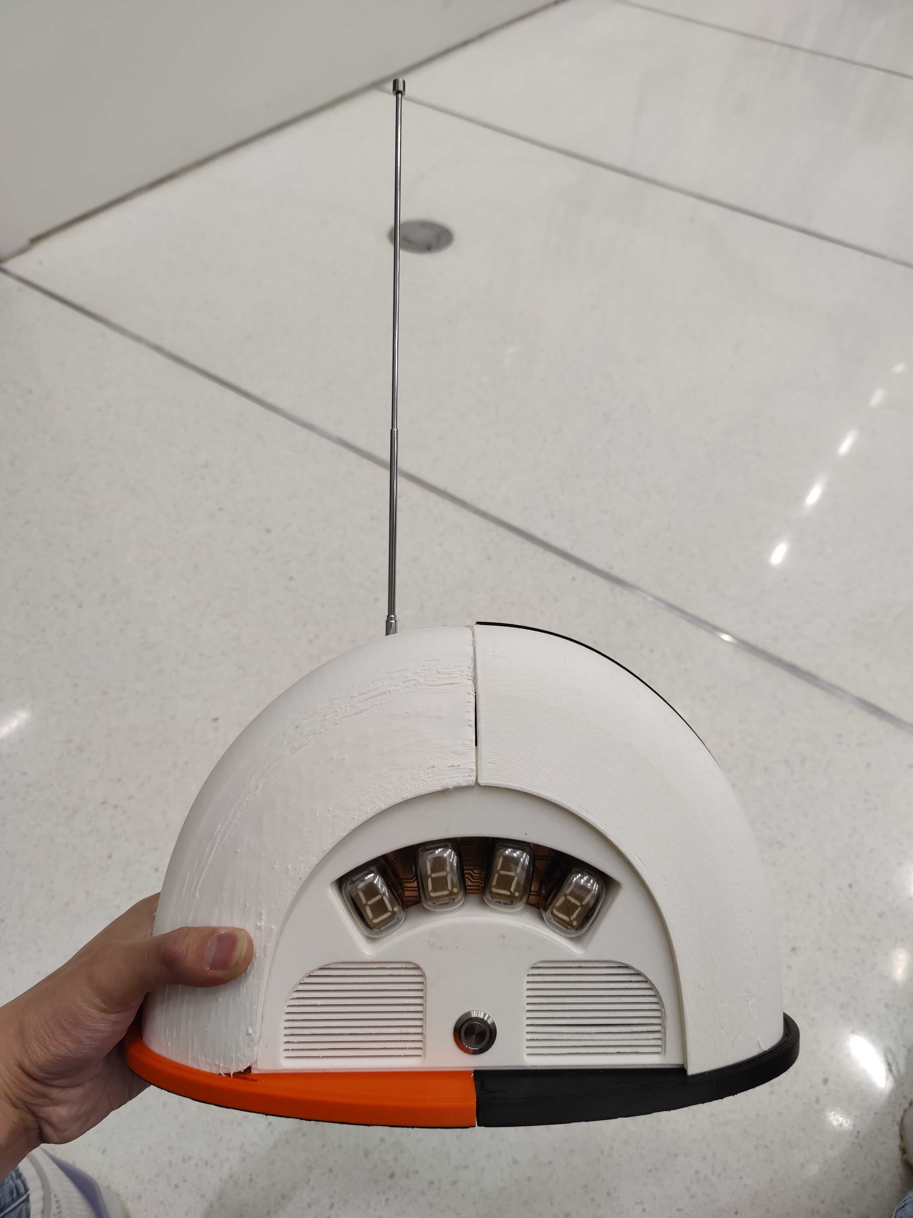
Full Assembly