HTMA Week 6: Prototyping a VFD board
Published: 2023-10-16Changes Since Week 5
Since last week, I’ve made major design changes to my schematic.
- The TPIC6B595 Power Logic Shift Register is basically out of stock everywhere, so we’re now going with a regular shift register with tons of transistors.
- Instead of driving LEDs, we’re going to drive IV-22 VFD tubes. Their theory of operation is similar enough to a nixie tube that we can simply build off of this prototype when the time comes to use real nixie tubes.
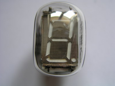
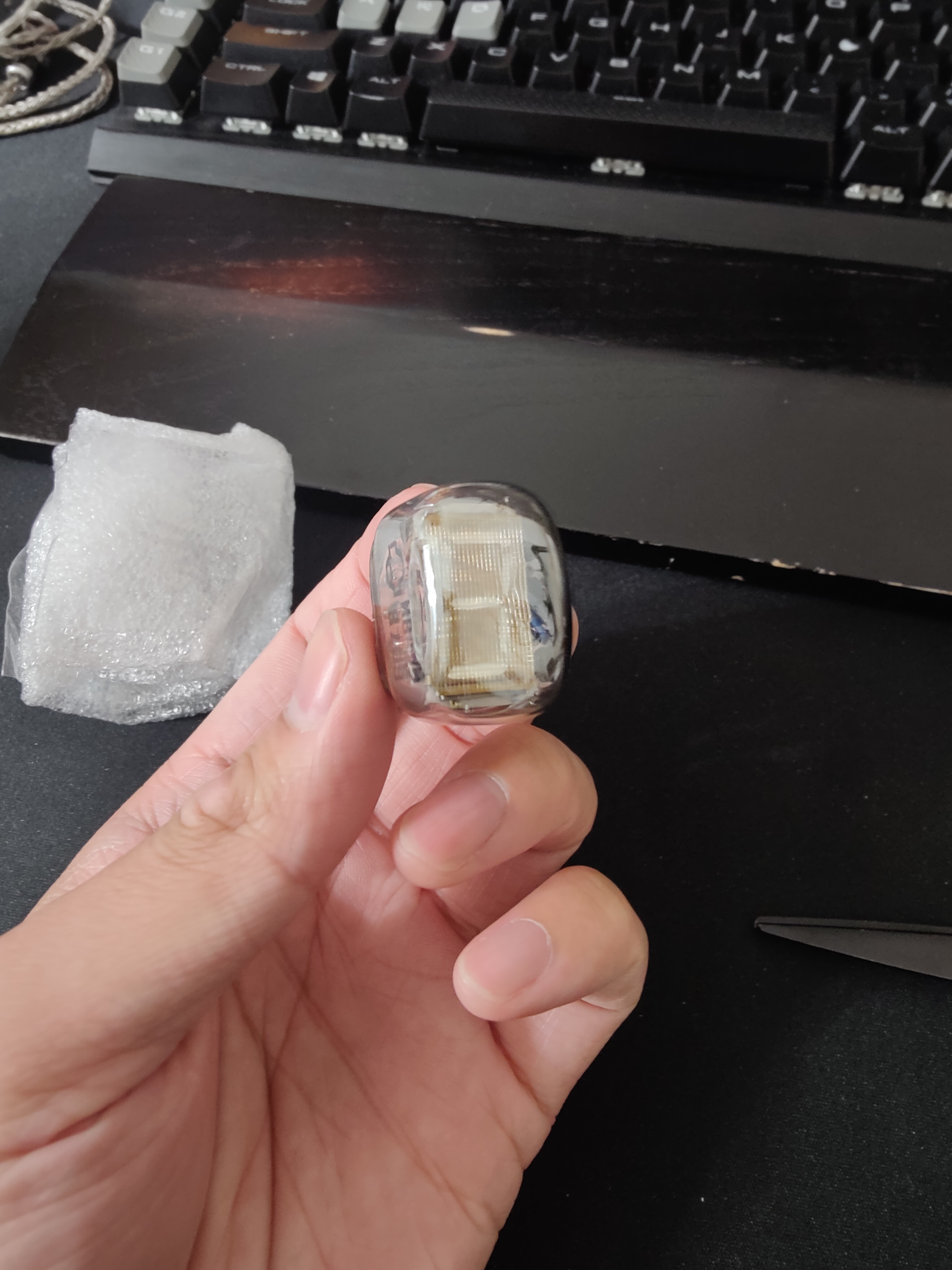
IV-22
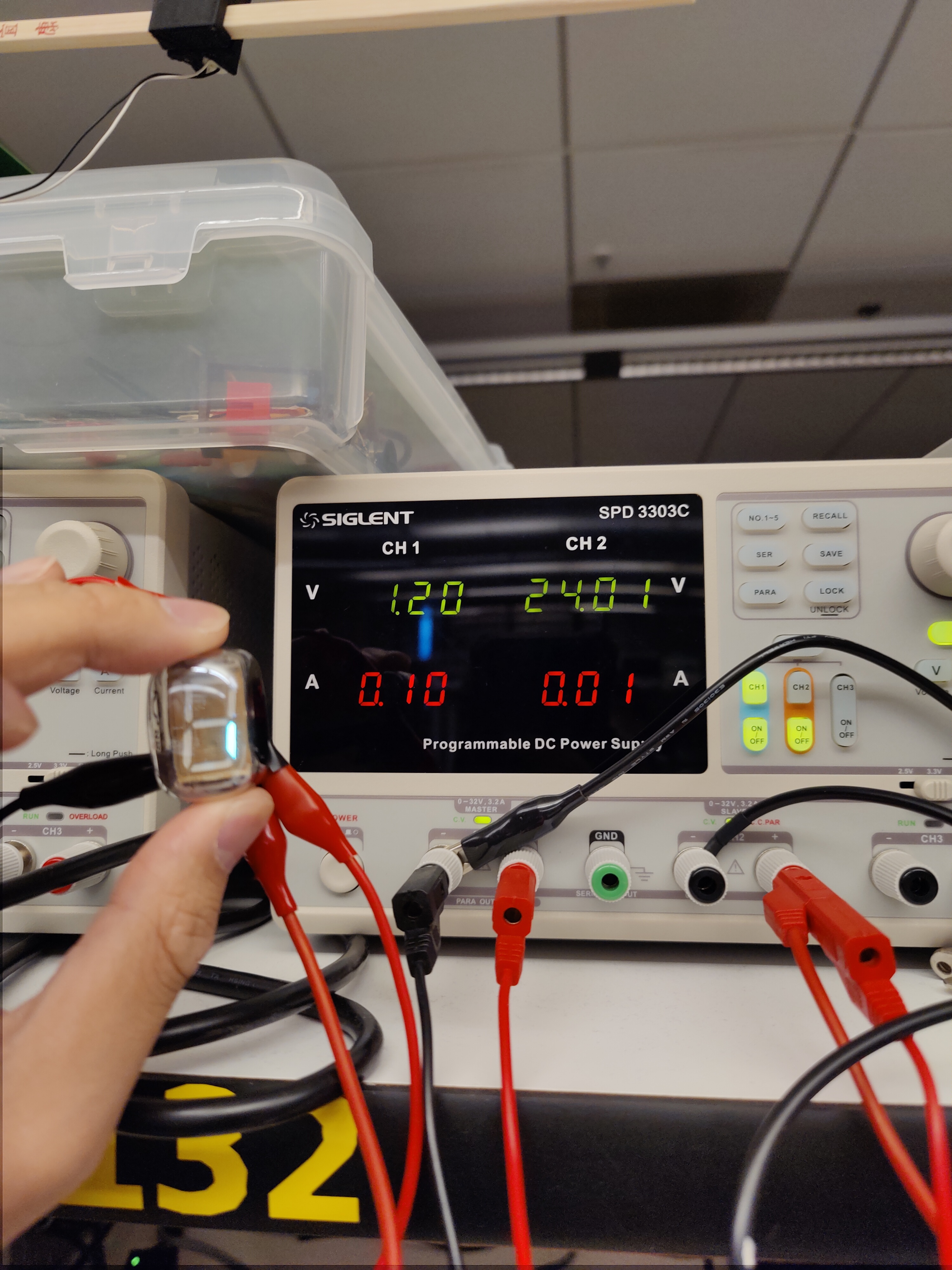
I received my IV-22 tubes from eBay. As with any online purchase from third party sellers, I need to test it. I used one of the programmable DC power supplies right outside of the EECS lab, and configured it according to the datasheet. After some fiddling and help from Anthony, I was able to get a segment to light up. I then proceeded to successfully test all 6 tubes that I received.
Schematic
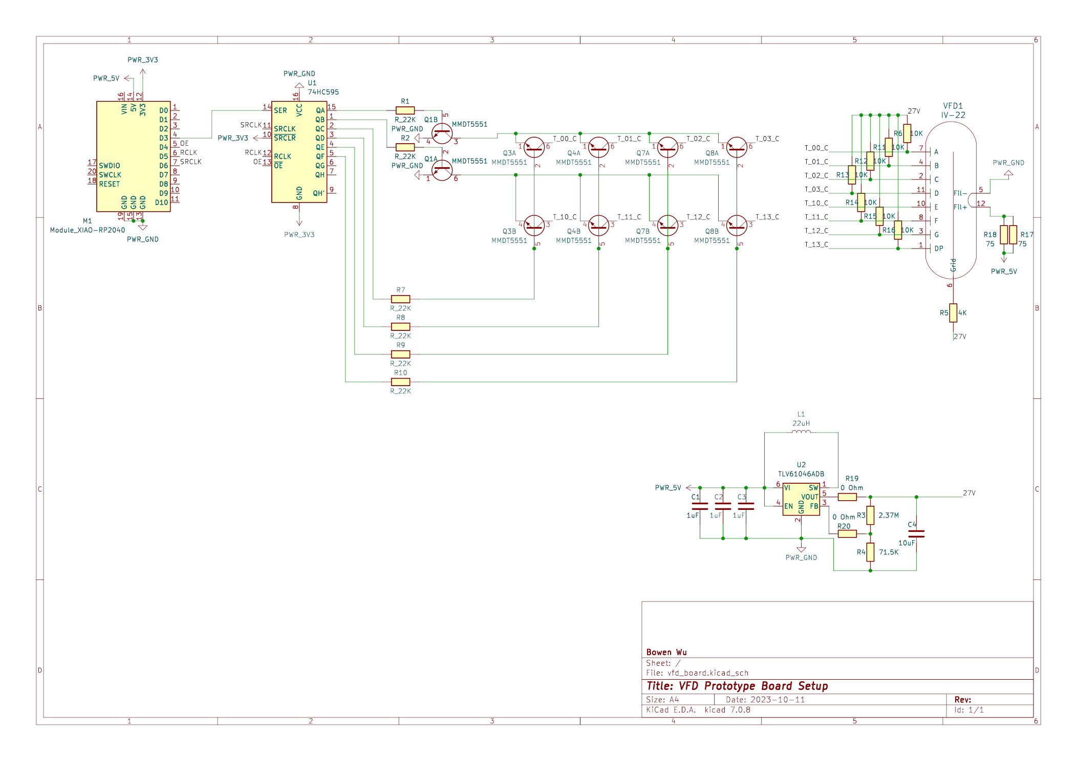
Transistor Matrix
For this prototype, we’re using a 2x4 transistor matrix setup to control the 8 anode pins on the VFD tube with 6 pins (design inspired by this Hackerday project). For the transistor matrix, I’m making use of the MMDT551 2-NPN transistor array. I’m using this IC because if I were to use individual transistors, for the final project I’d need to lay out 50 transistors by hand; with this I’d only need 25.
Since we don’t have access to the TPIC6B595, I’ll be using the 74HC595 shift register to control my transistor gates, same as the Hackerday project.
Power
For the power supply, I’m still using the TLV61046A from last week with the same design.
PCB Layout
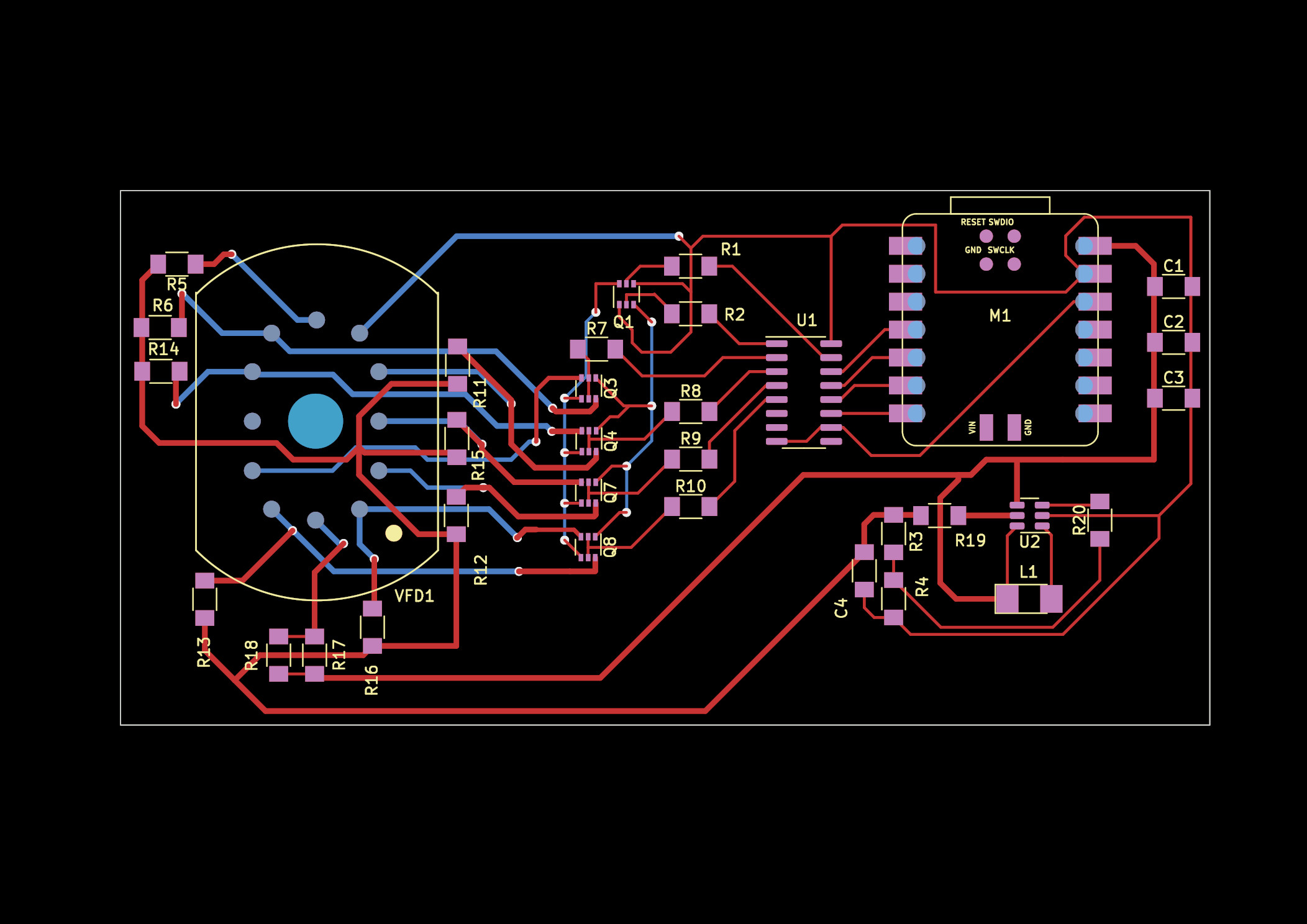
A simple overview:
- M1 -> Xiao
- Net around U2 -> Boost Converter providing 27V
- U1 -> Shift Register
- Q# -> Transistor Arrays
- VFD1 -> IV-22 VFD Tube
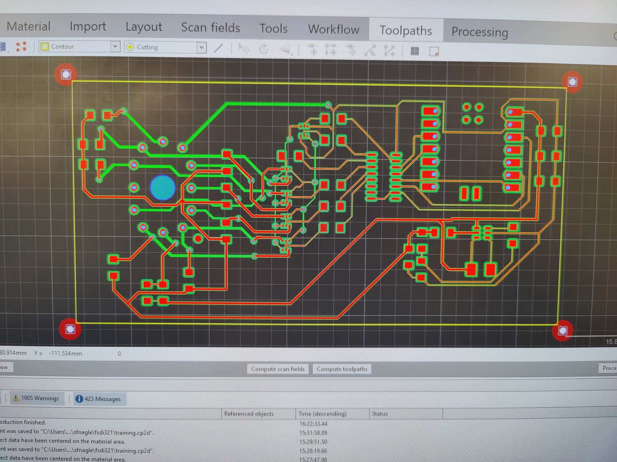
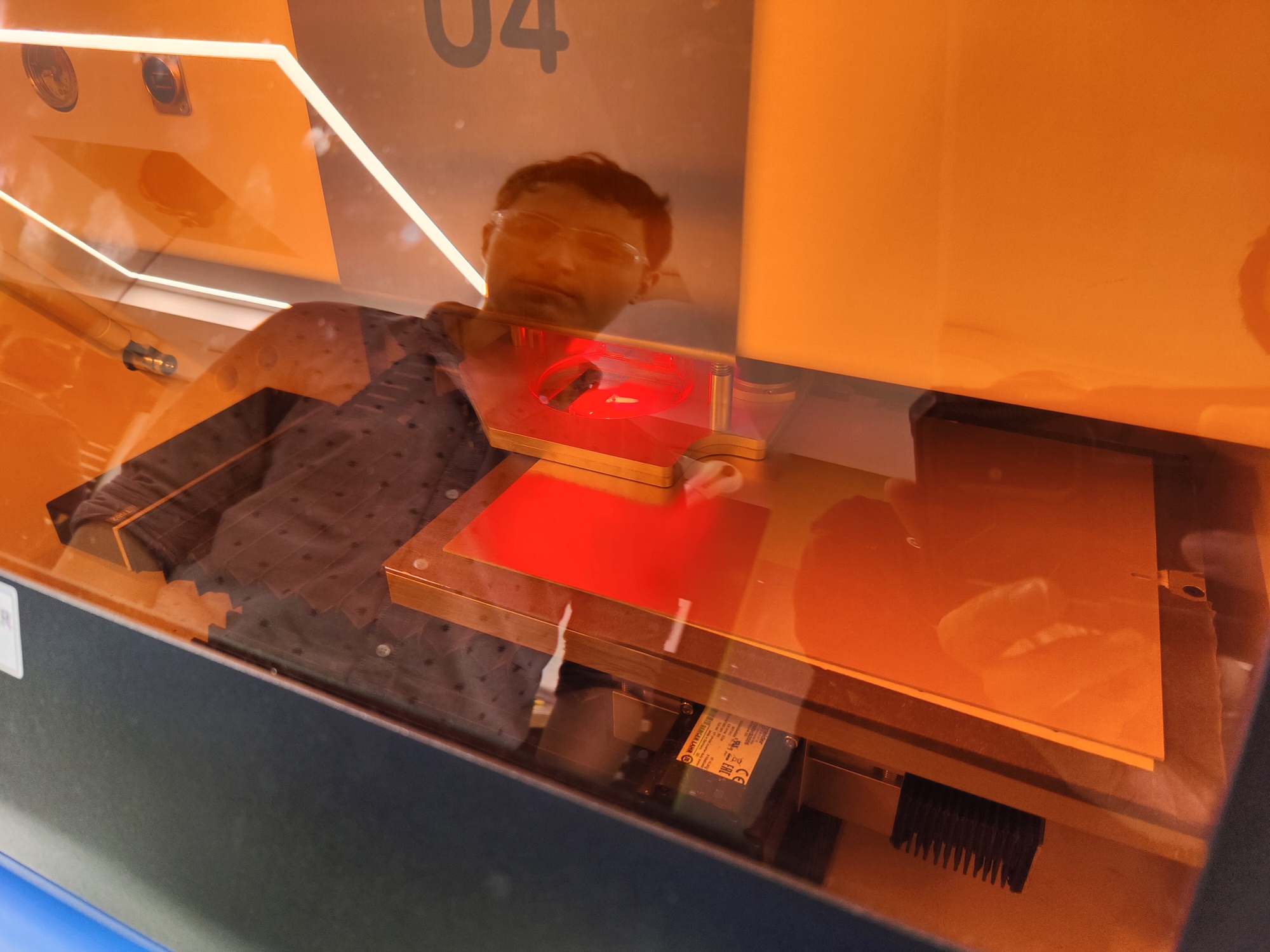
PCB Fabrication
Because of the small footprints that I have, Anthony took me to Research Laboratory of Electronics (RLE) in building 36 to borrow their laser PCB fabricator from Steven Nagle. This process would give the precision needed for my components, specifically the transistor arrays and boost converter.
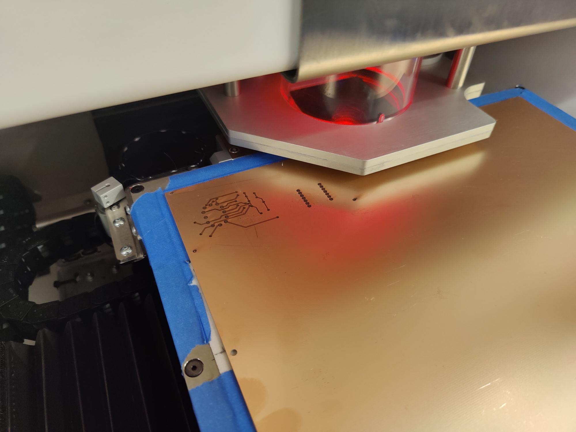
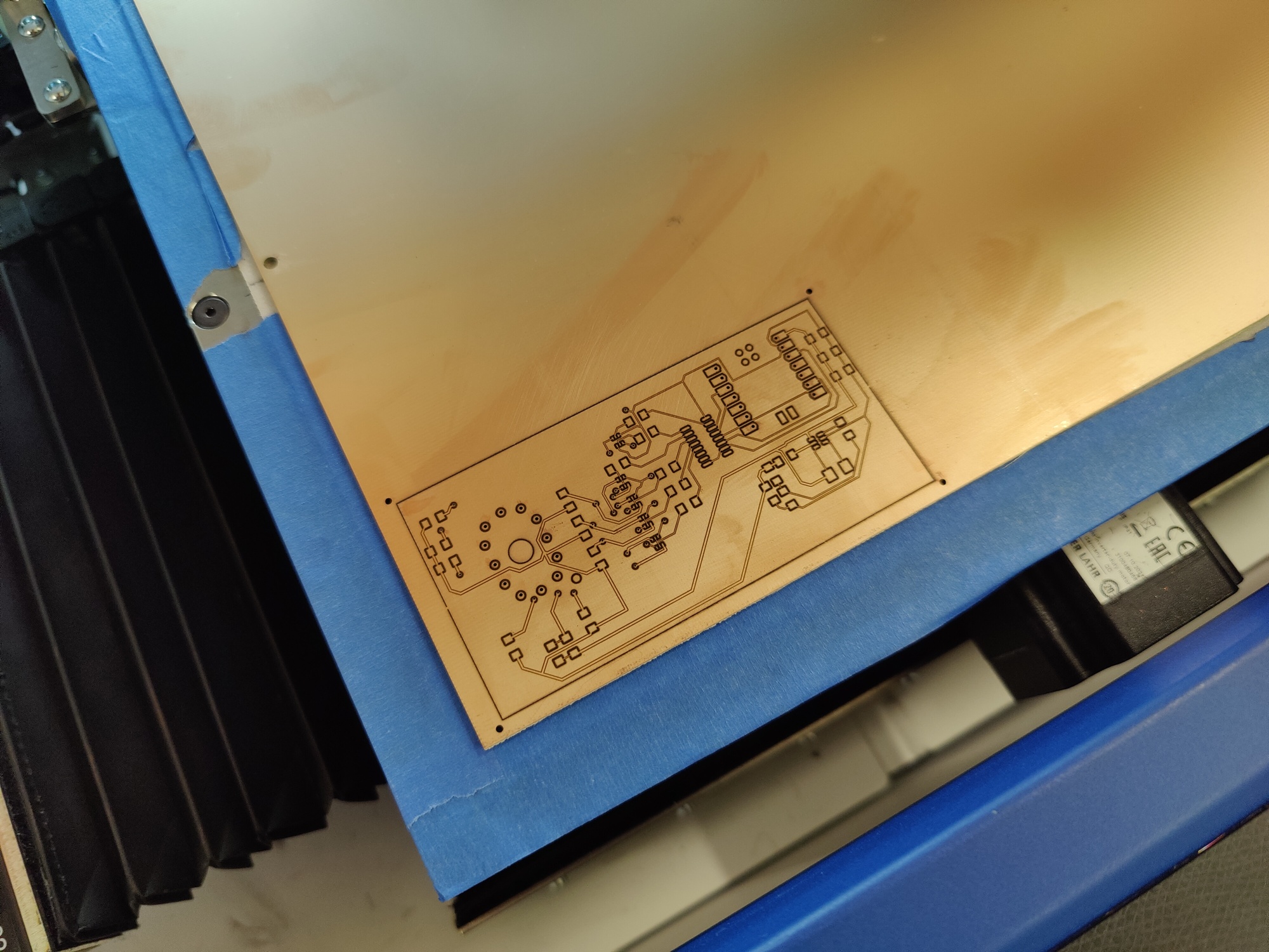
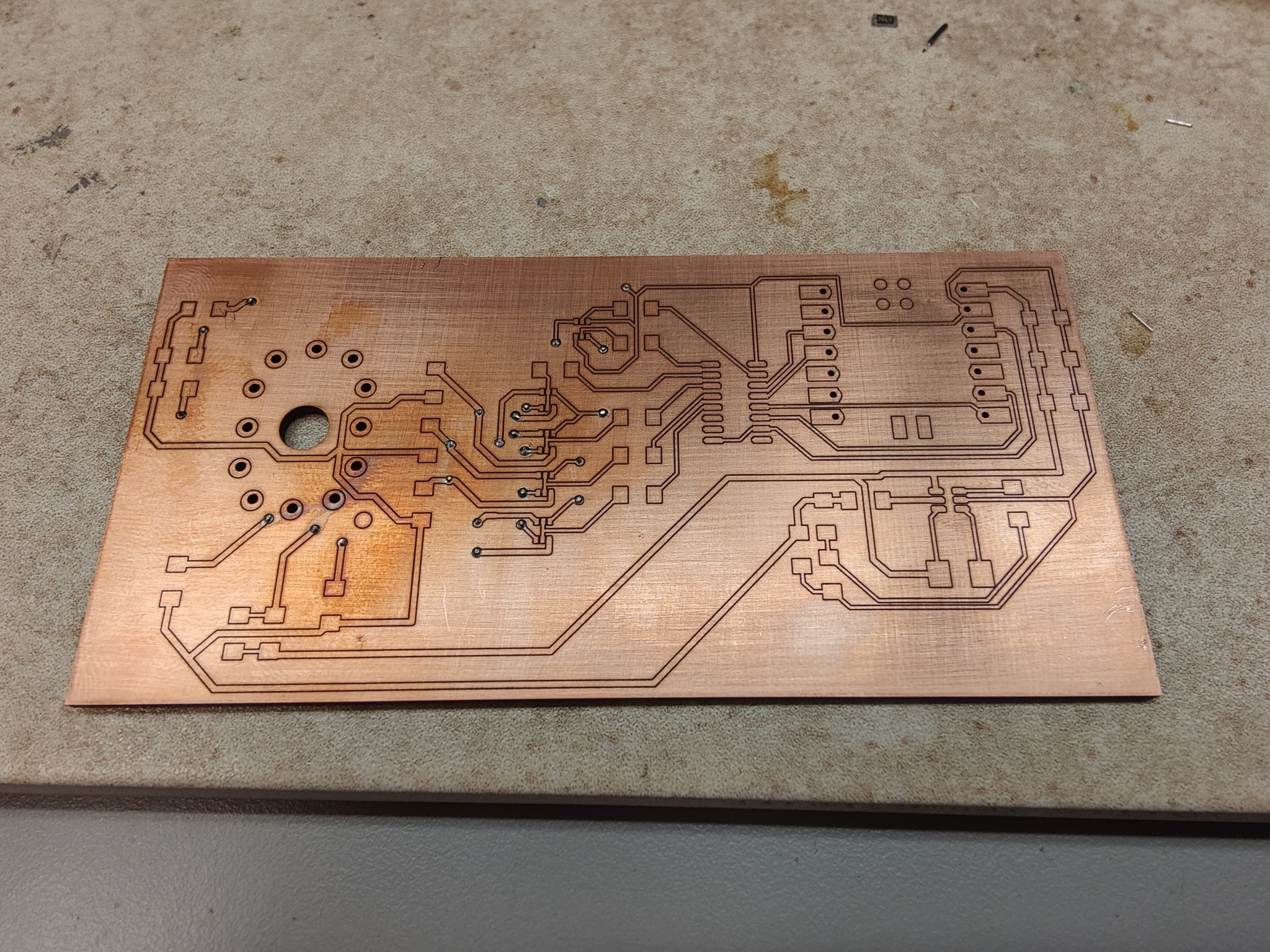
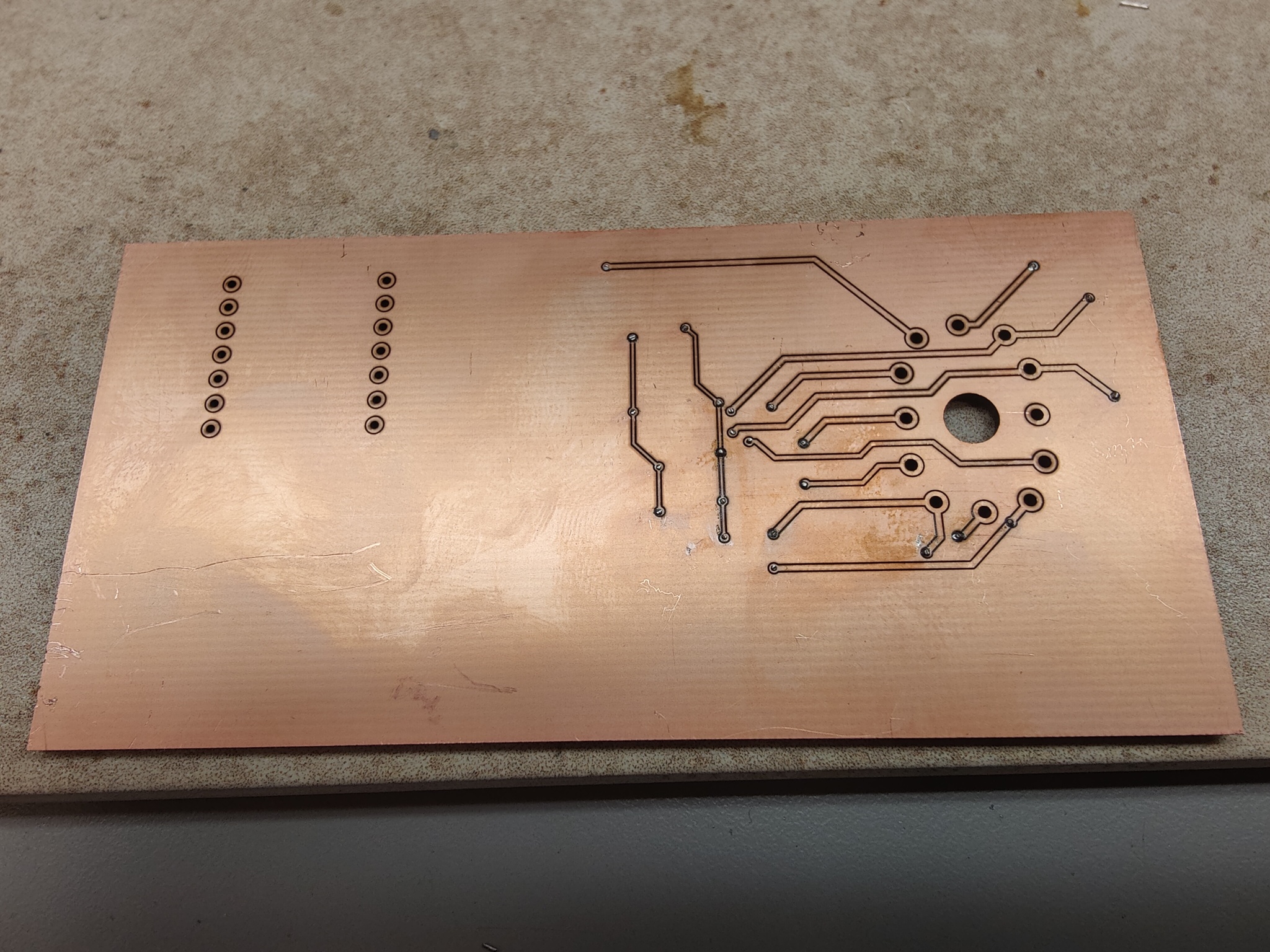
Unfortunately, I didn’t double check my footprints and the holes for the VFD tube were too small. So I had to make some adjustments and ask Steven to make a second run for me. Turns out the second run had a mistake with only 15um isolation for the traces, which was way too small. So my final board came out in the third run. Both shown in the image below.
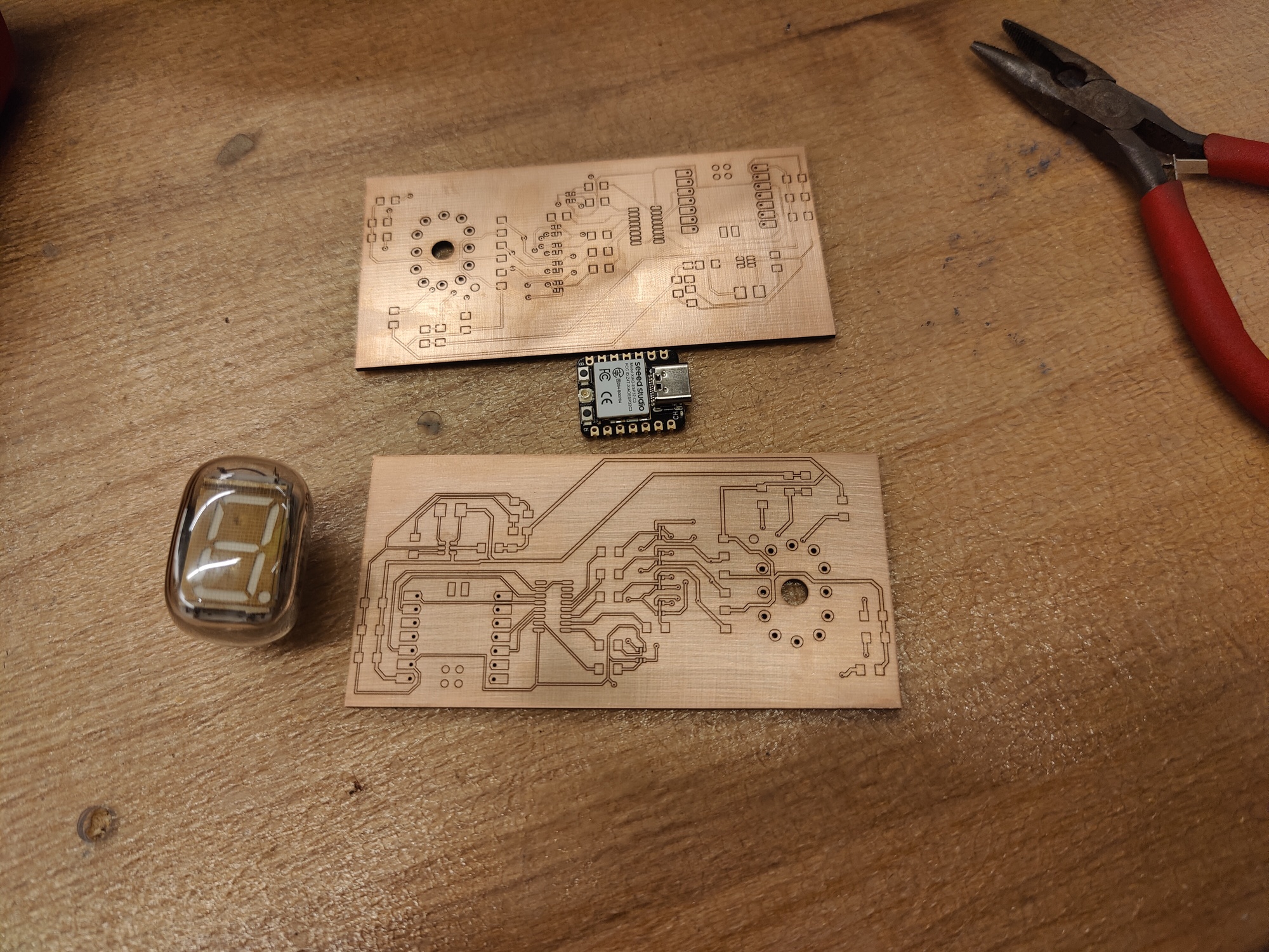
Top board has 15um trace isolation, bottom board has proper trace isolation
Filling Vias
Because I made the vias on the board so small, I couldn’t use rivets to connect the two side. Instead, at Steven’s suggestion, I pushed a thin wire through each via and soldered each side with a tiny bit of solder paste, then clipped them off.
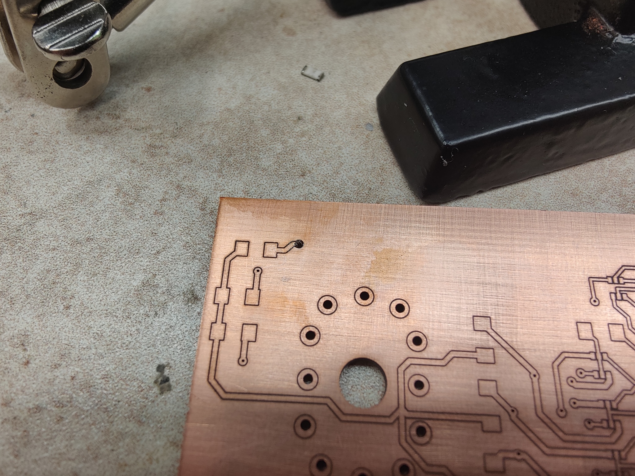
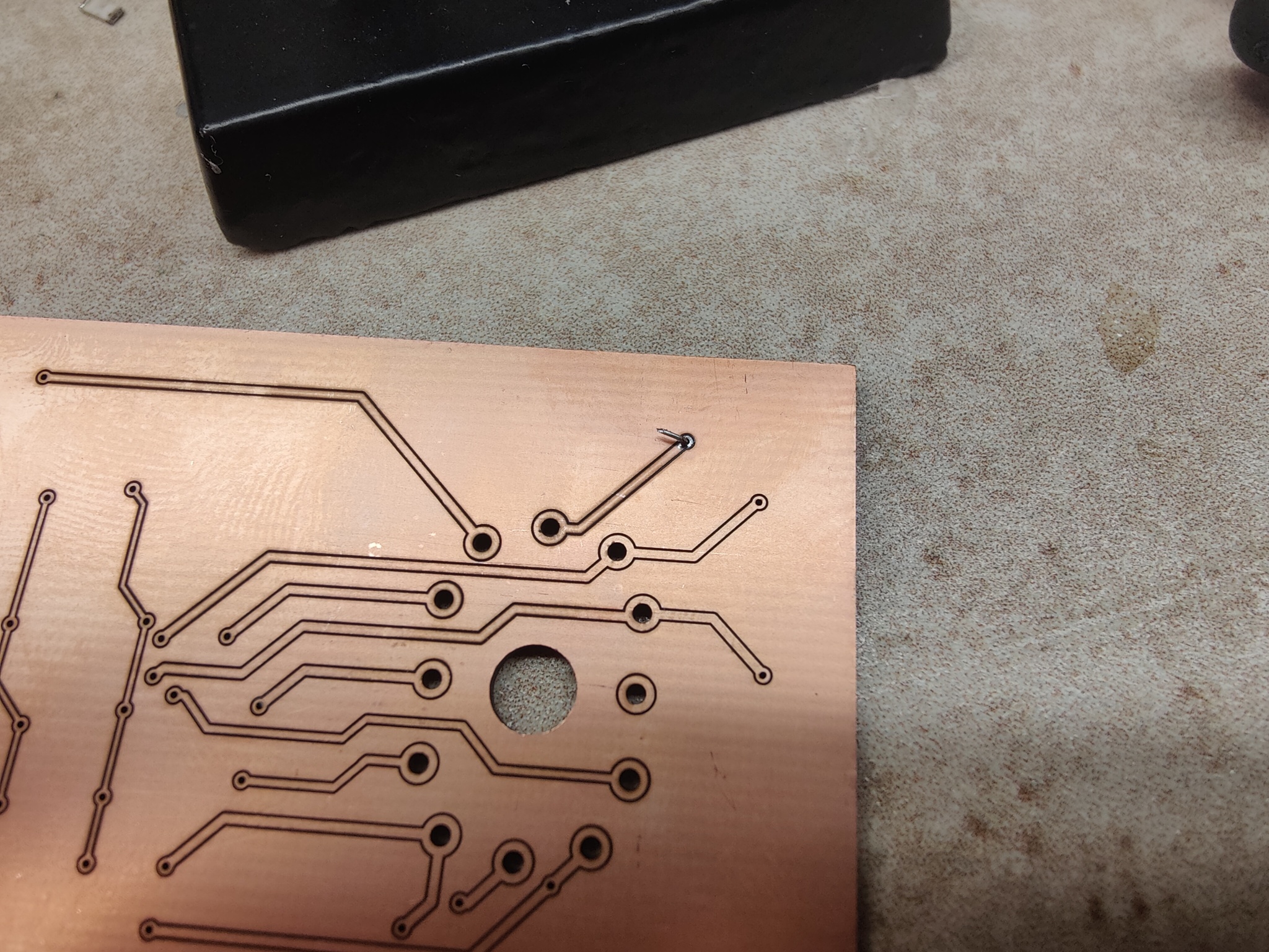
I then did this for all vias. After an hour or two, I have a finished bare copper board.
After many days of painstakingly hand soldering these tiny components, I finally have a finished board.
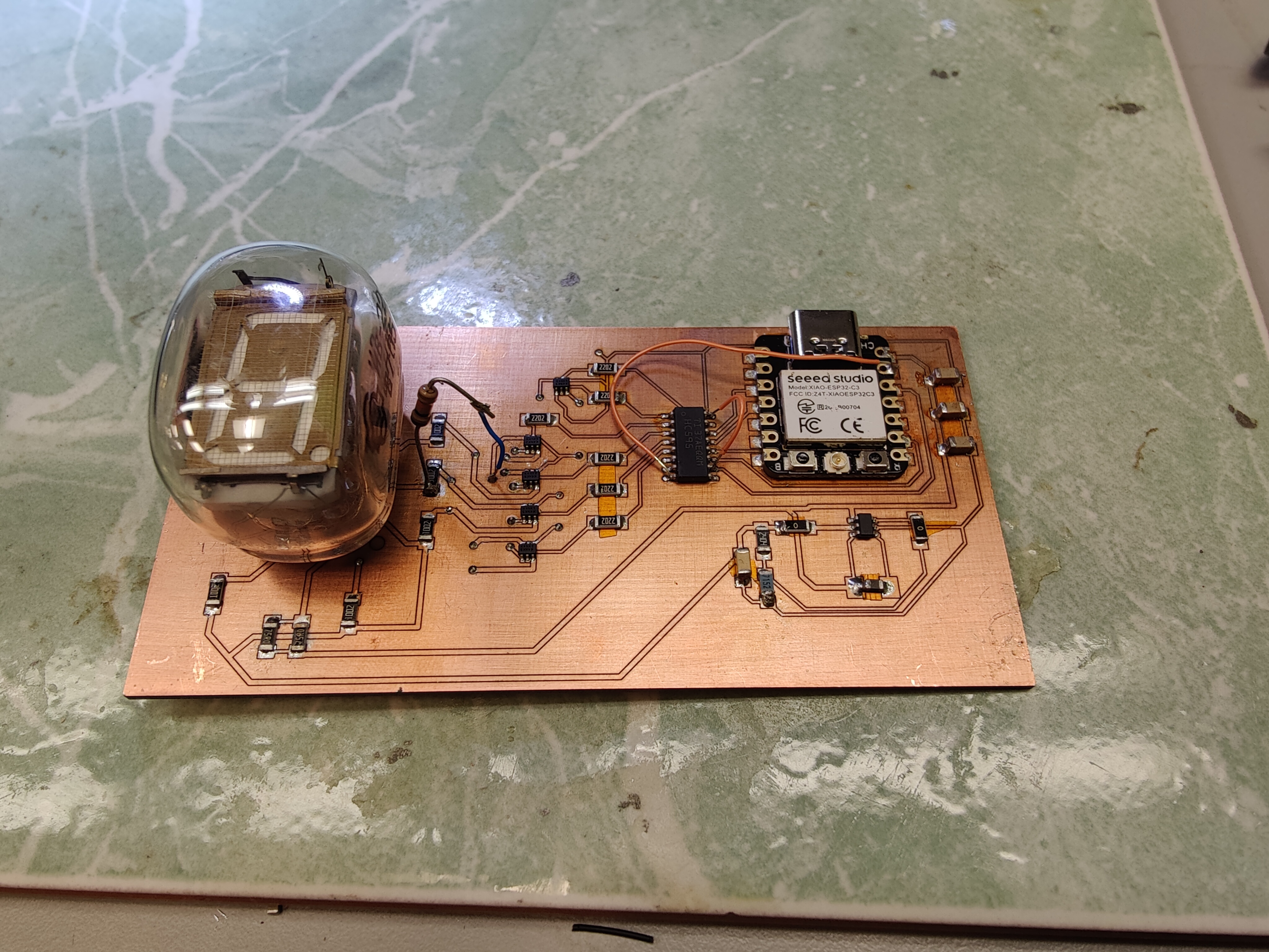
Unfortunately, this board had many issues:
- I merged designs that I’ve seen on the net without thinking too much. This led to a design issue that prevents me from properly operating the VFD.
- Each anode is pulled up to 27V, but I have a 2x4 transistor matrix to pull it down, where the 8 anode pins are split into 2 groups.
- This means that I can only control which segment is turned off for each group, however I cannot turn off two segments at the same time if they belong in different groups.
- I flipped 3.3v and ground on the shift register, hence I had to do surgery with the orange wires.
- Whatever material the pins of the VFD was made out of does NOT like to adhere to solder, so I had to just try to smother it in solder to make a connection.
- I had forgotten to place a resistor for one of the VFD anode, hence the through-hole resistor coming out of the board.
- There were many small places that actually shorted parts of the 27V rail to the surrounding copper plate.
- Anthony helped me to identify and remove those shorts. I then grounded it.
- I couldn’t source exactly 2.37M Ohm for my boost converter, so I had to use 2.40M Ohm. Therefore, instead of 27V we have 28V, but it isn’t much of an issue.
Software
While I had downtime from working on the physical components, I wrote up some simple firmware.
Configuring Shift Register
I created a shift register class to handle sending out data:
class ShiftRegister {
  public:
    ShiftRegister(){};
    // Shift 8 bits of data into the register and update its output
    void shift_data(uint8_t data);
    // Enable the shift register and clear it
    void init(int dataPin, int sClkPin, int rClkPin, int oePin);
  private:
    int dataPin;
    int sClkPin;
    int rClkPin;
    int oePin;

    // Shift one bit into the register
    inline void shift_in_bit(bool bit);
    inline void pulse_shift_clock();
    inline void pulse_register_clock();
};
Matrix Limitation
The intent was to rapidly flash segments so that they make up a whole number. But because of the aforementioned design flaw, that’s impossible. Therefore, we are limited to only the following digits and letters.
constexpr uint8_t VFD_DIGIT_0 = 0b01001000;

constexpr uint16_t VFD_DIGIT_6 = 0b10010000;

constexpr uint16_t VFD_DIGIT_8 = 0;

constexpr uint16_t VFD_DIGIT_9 = 0b01100000;

constexpr uint8_t VFD_DIGIT_A = 0b10000100;

constexpr uint8_t VFD_DIGIT_B = 0b10110000;

constexpr uint8_t VFD_DIGIT_E = 0b10011000;

constexpr uint8_t VFD_DIGIT_F = 0b10011100;

constexpr uint8_t VFD_DIGIT_H = 0b10100100;

constexpr uint8_t VFD_DIGIT_P = 0b10001100;
Source Files
Source Code Schematic and Layout