HTMA Week 9: Input Devices
Published: 2023-11-01Preface
For my final project, I wanted the VFD clock to be able to automatically adjust its brightness according to the environment’s light level. To achieve this, I needed to use a phototransistor, a device that responds to its light level.
Hardware Design
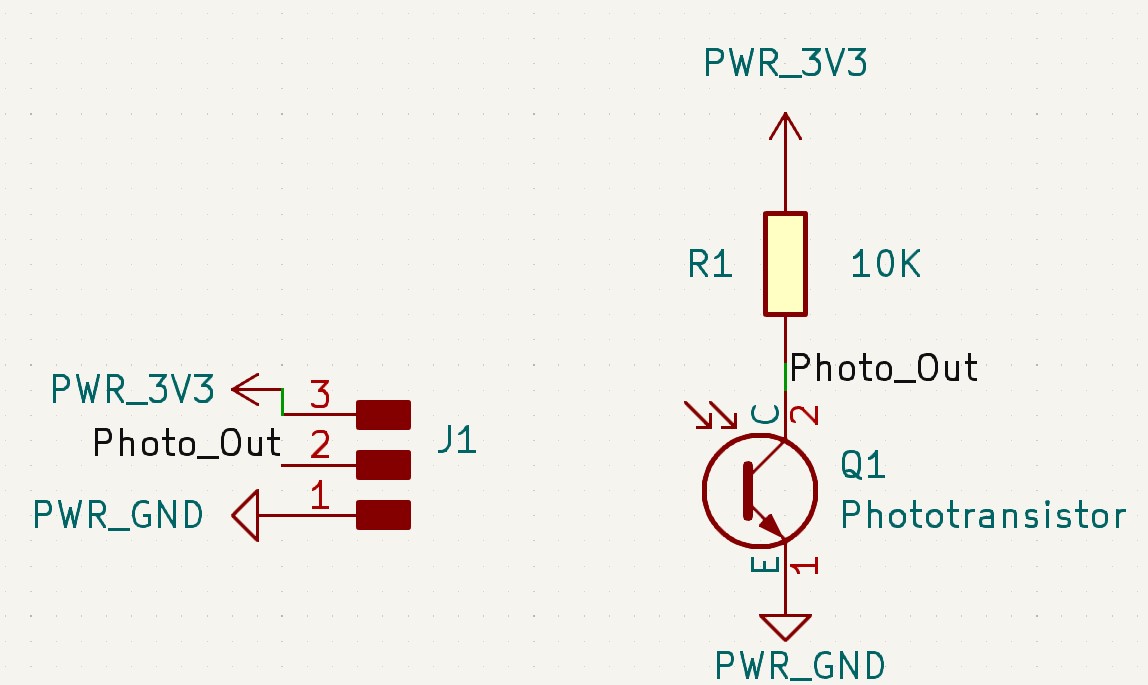
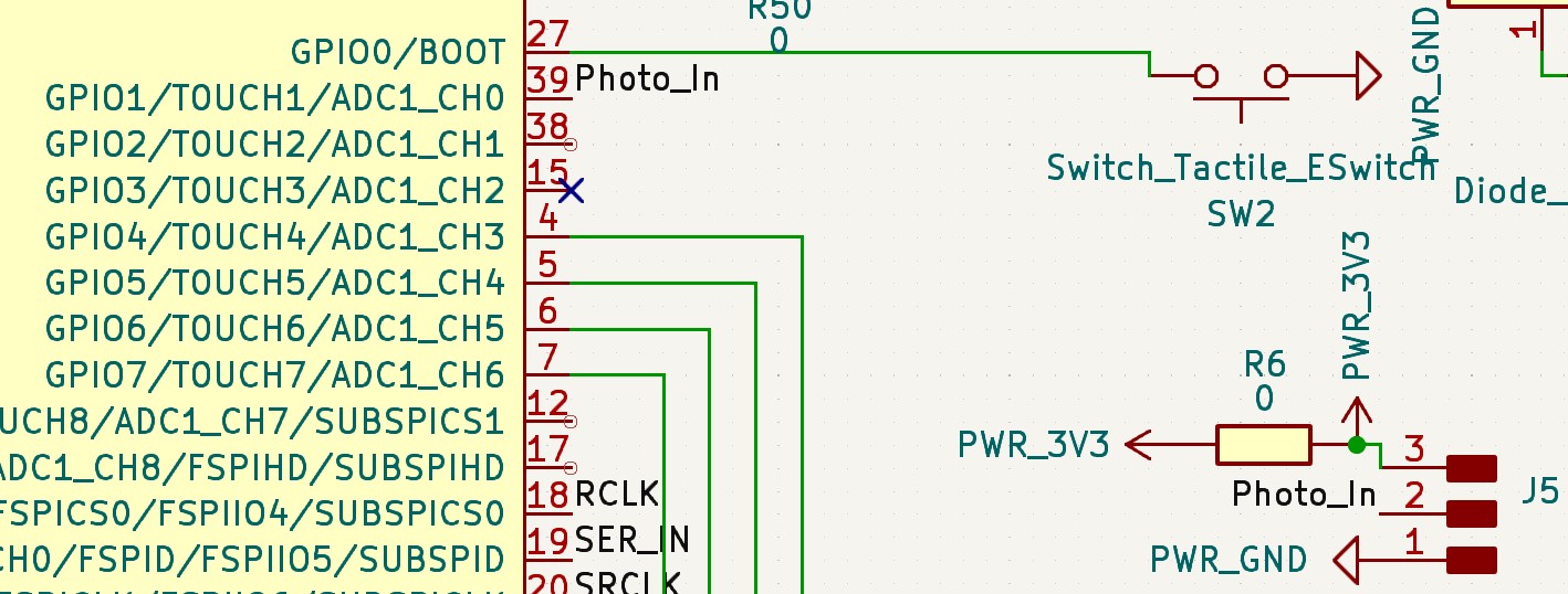
The phototransistors that the EECS section had in stock was the PT15-21C/TR8. The more photons it receives, the more current it will let through its collector and emitter. So we can put it in series with a resistor at the collector, and measure the voltage at the collector.
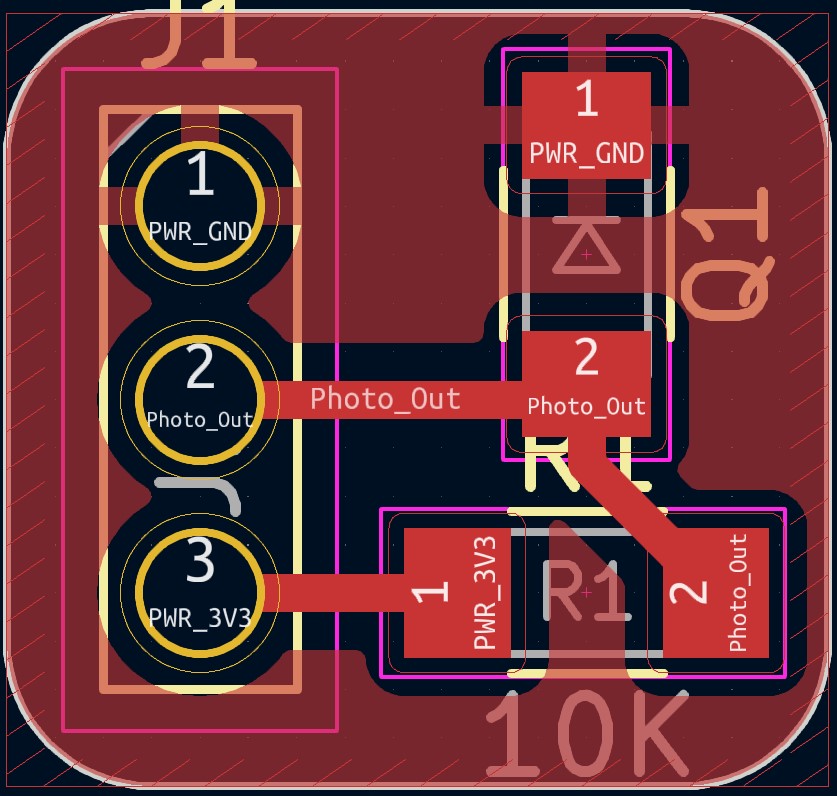
I decided to put this on its own board, with the following schematic and small board.
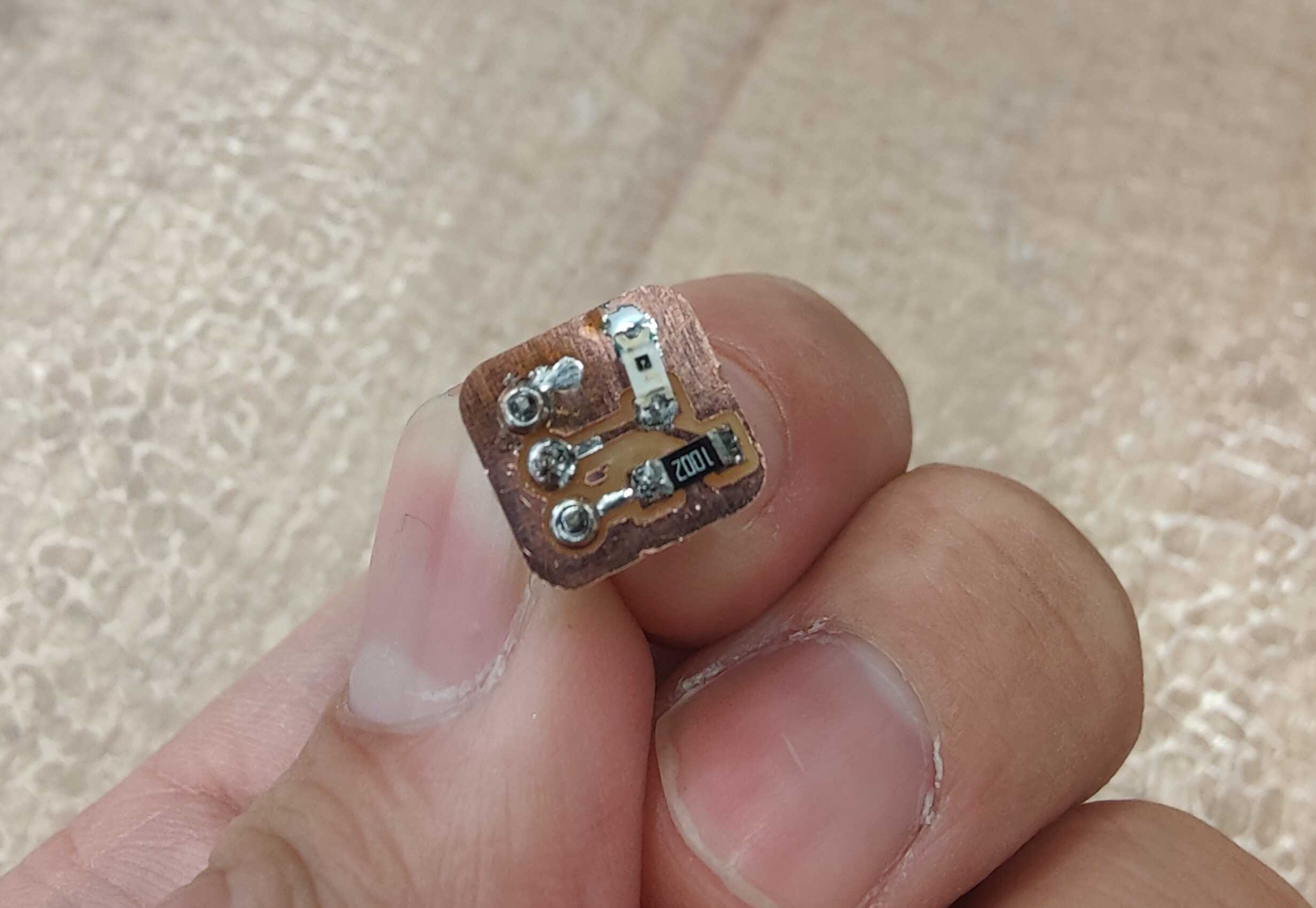
Hardware
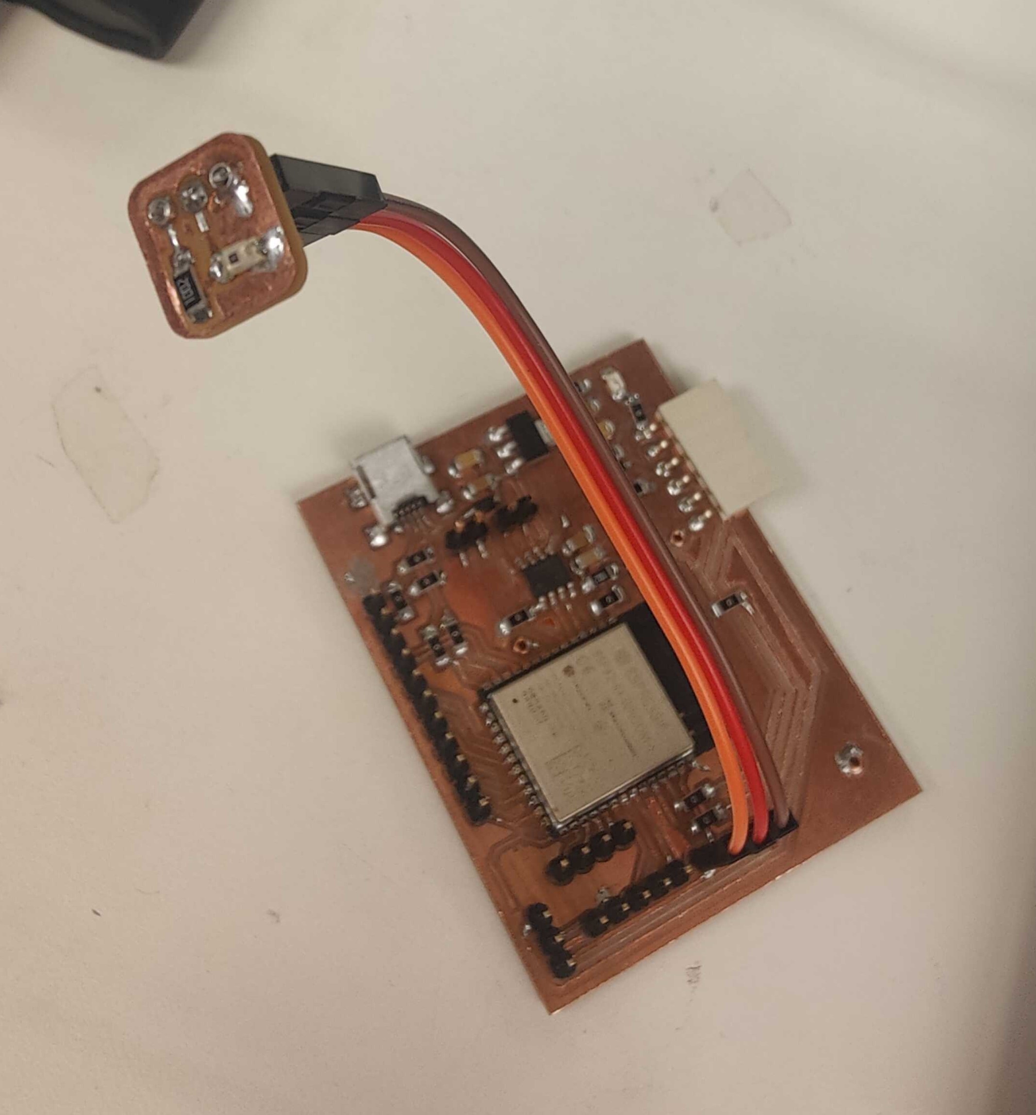
After a quick mill and some solder, I had a small module that can easily be connected to my main board.
Photon Response
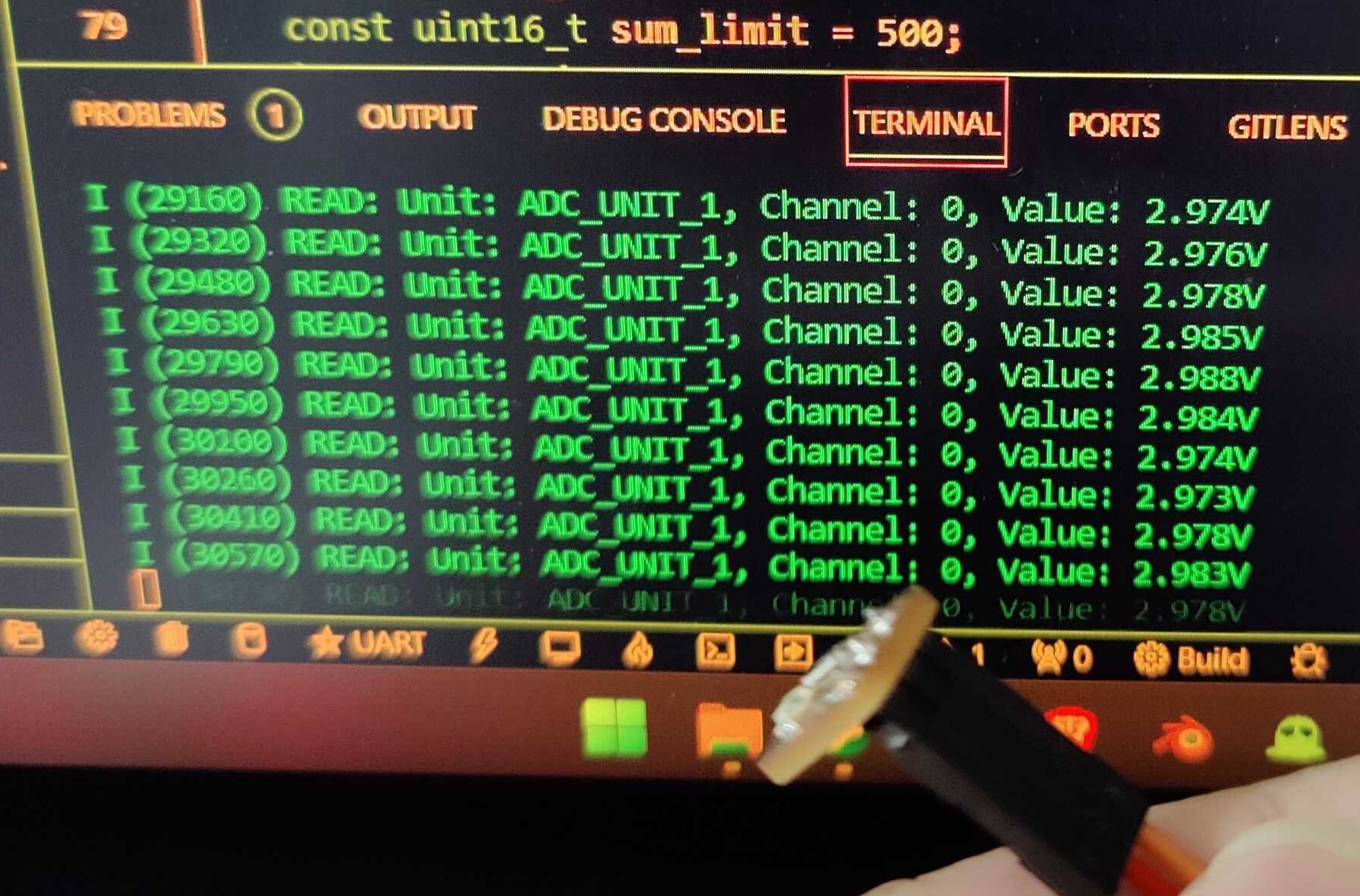
I then tested the voltage response to light, here are my results:
- In EECS lab, I see about 2.7V without anything obstructing the phototransistor
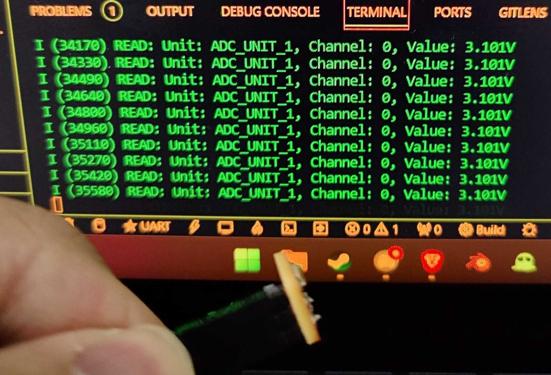
- If I put my finger on it, I see about 3.15V
This indicates to me that the more photons hit the phototransistor, the more current it allows through, so there is a larger voltage drop across the 10K resistor.
Software
To measure the voltage between the phototransistor and resistor, we must use an Analog to Digital Converter (ADC) on our microcontroller. For the ESP32-S3, that’s GPIO 1, which I’ve connected to the pin header that connects to the light sensor board.
To use the ADC on the ESP32-S3, I followed this example along with the API reference. However, some things to be aware of is that
- The ESP32-S3 must use type 2 output format during ADC configuration, this means the output format uses 12 bits.
- The ESP32 runs on an Real Time Operating System (RTOS) by default, which has timeouts on tasks. If you use an infinite loop like your typical arduino code to run your main program, then the watchdog timer will trigger and prompt a reset on your microcontroller.
- To resolve this, one way is to use
vTaskDelay(1);at the end of your while loop.
- To resolve this, one way is to use
- The callback function and RTOS task used in the example is not necessary to get things to work.
ADC Input Range
Another thing that caught me offguard is that the ADC of the ESP32-S3 has a limited range of voltages it can measure. According to the adc calibration page, the reference voltage in the ESP32-S3 is 1100mV. This is the formula for converting your 12 bit outputs to voltages:
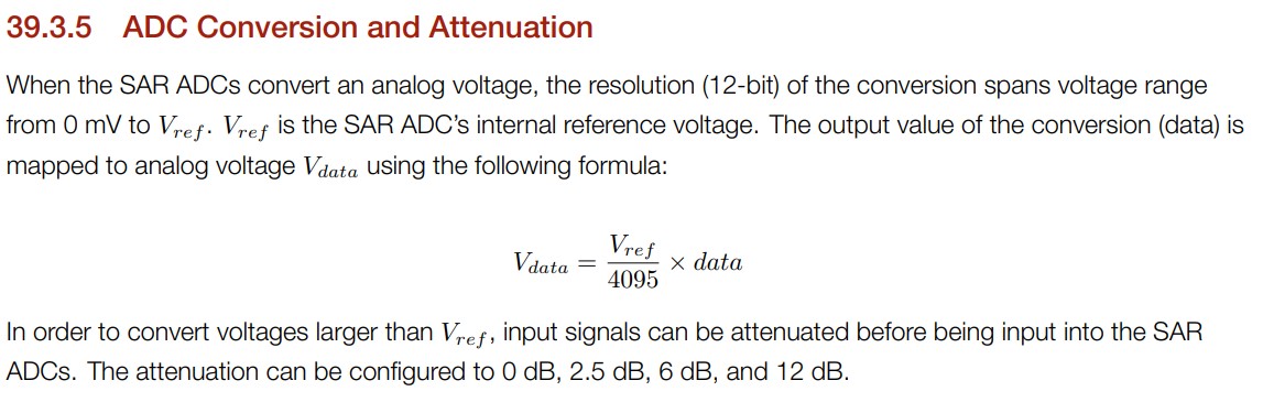
This means that the most voltage you can measure is the reference voltage, 1.1V. I tried using the highest attenuation value of 11dB (though it says 12dB in the manual), but that still barely gets me a good range of light to measure.
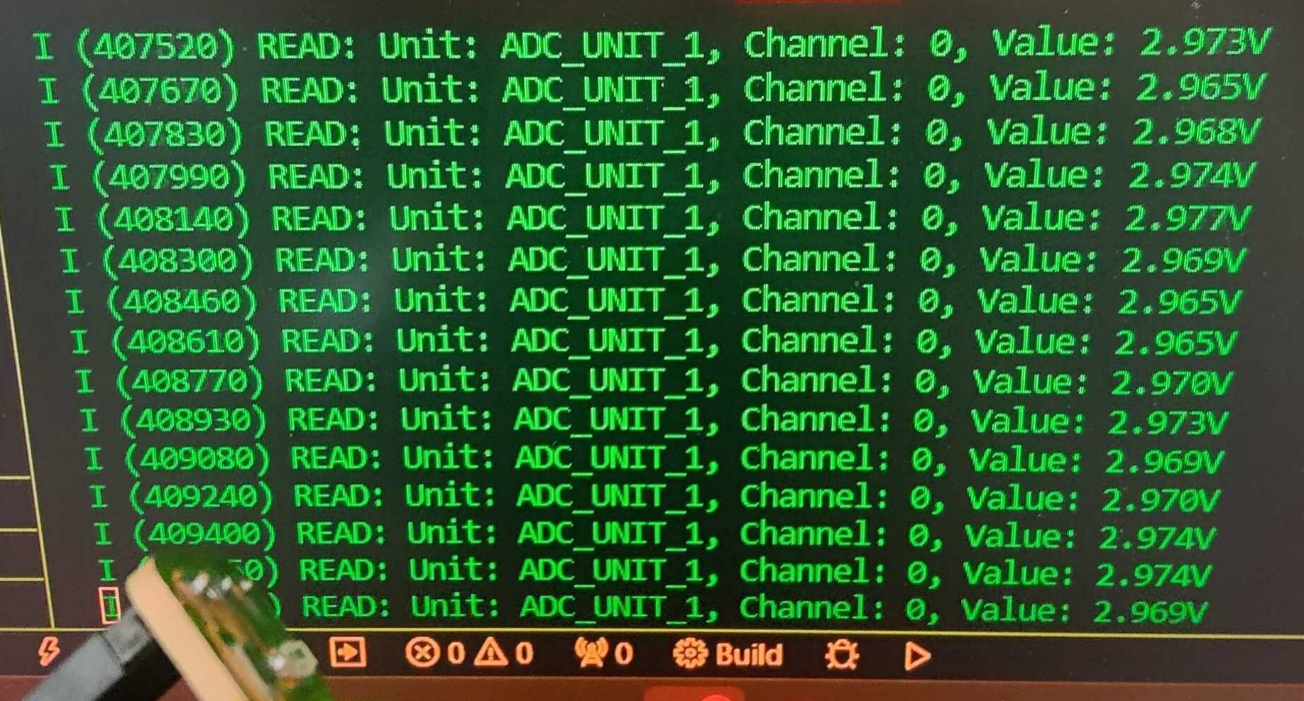
In my room, when I point the sensor to somewhere slightly darker, the voltage measurement is clamped to 3.1V (value of 0xFF), while it only measure 2.7V when I point it towards a lamp light.
This indicates to me that I need to use a resistor larger than 10K to be able to properly measure darker areas, so I switched the resistor to 50K.
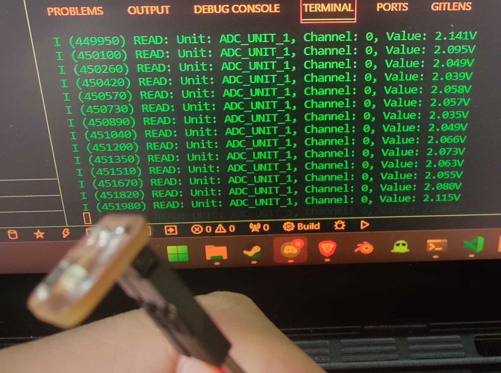
Now the measurement is no longer clamped to 3.1V as quickly as before.