Progress


Hey there! My name is Jesus and I am a Junior Majoring in 6-2 (Electrical Engineering and Computer Science) and Minoring in 2 (Mechanical Engineering). I'll be using this website to document my progress in this class so feel free to take a look around!
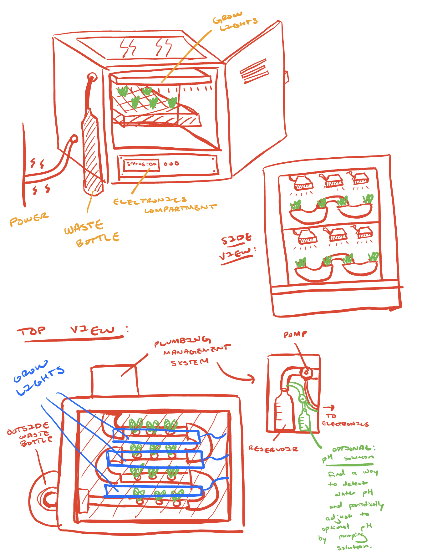
For the first week, we were tasked with brainstorming ideas for a final project. I have always wanted to make some kind of automatic hydroponic garden that would automatically water and provide light for my plants. If I do end up doing this as my final project I think it would be able to easily incorporate a lot of the various skills we'll be learning in the course.
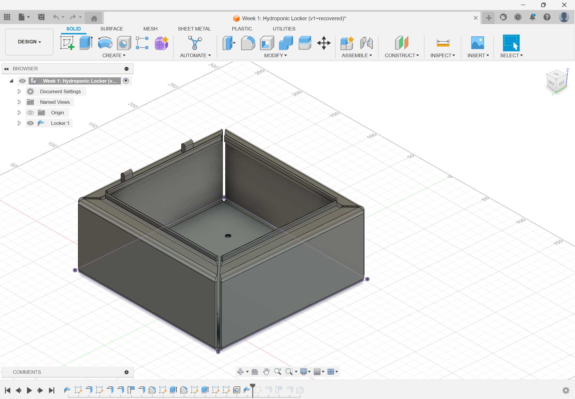
The sketch above is my idea for a 'Hydroponic Locker'—a kind of all-in-one that would have some electronics to regulate everything by itself. After doing the sketch, I also made a basic CAD to get an idea of what the locker could look like made out of sheet metal.

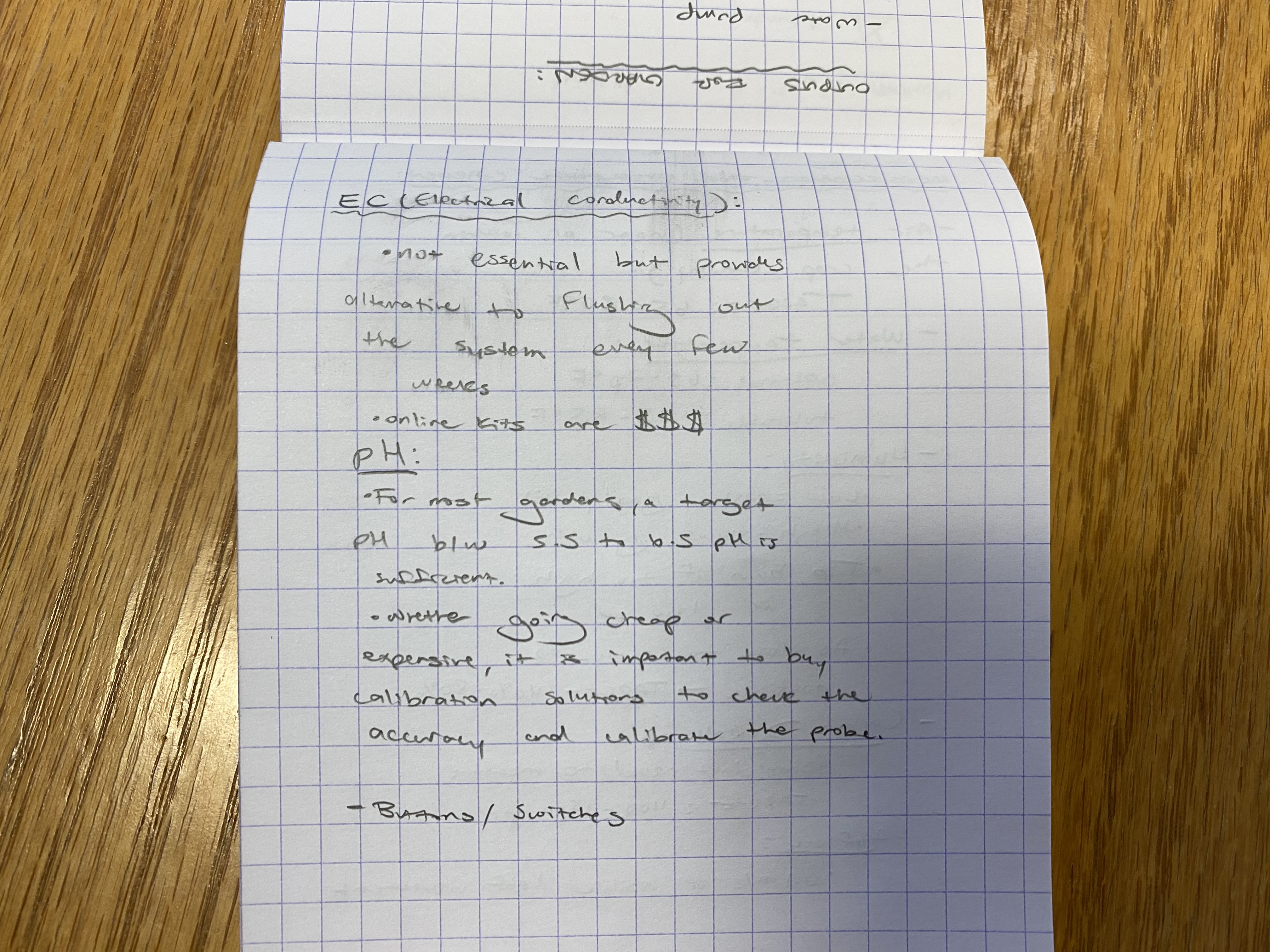
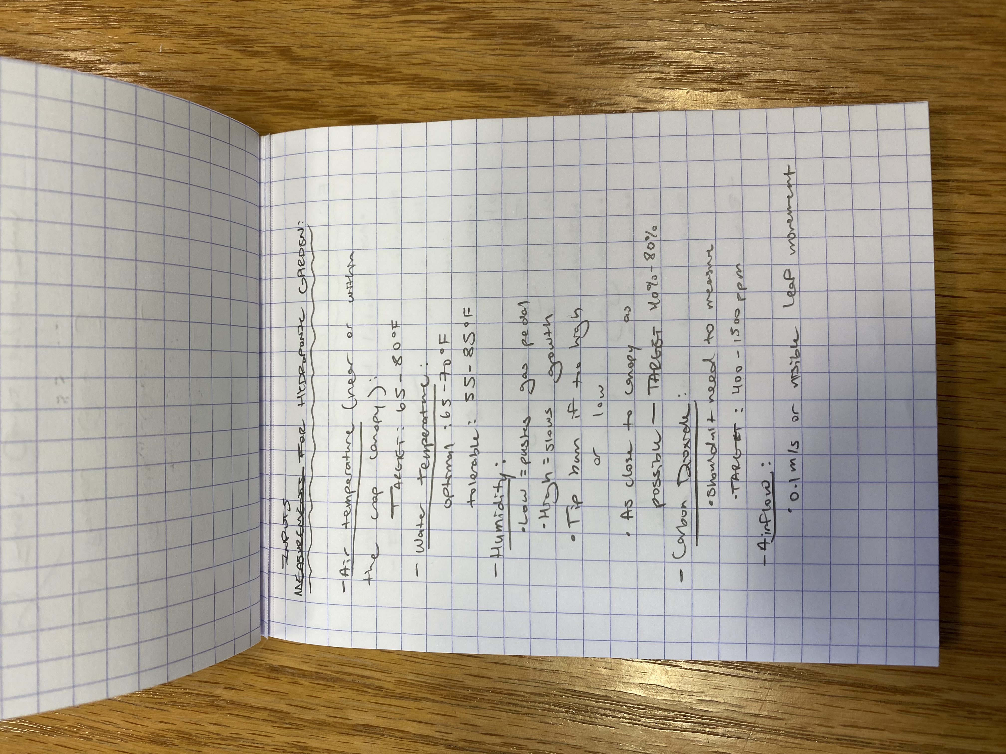
In preparation for inputs and outputs week, I also thought it would be a good idea to get an idea of which devices I'd need for the project. Here are some of my notes:
You can access the CAD file here.
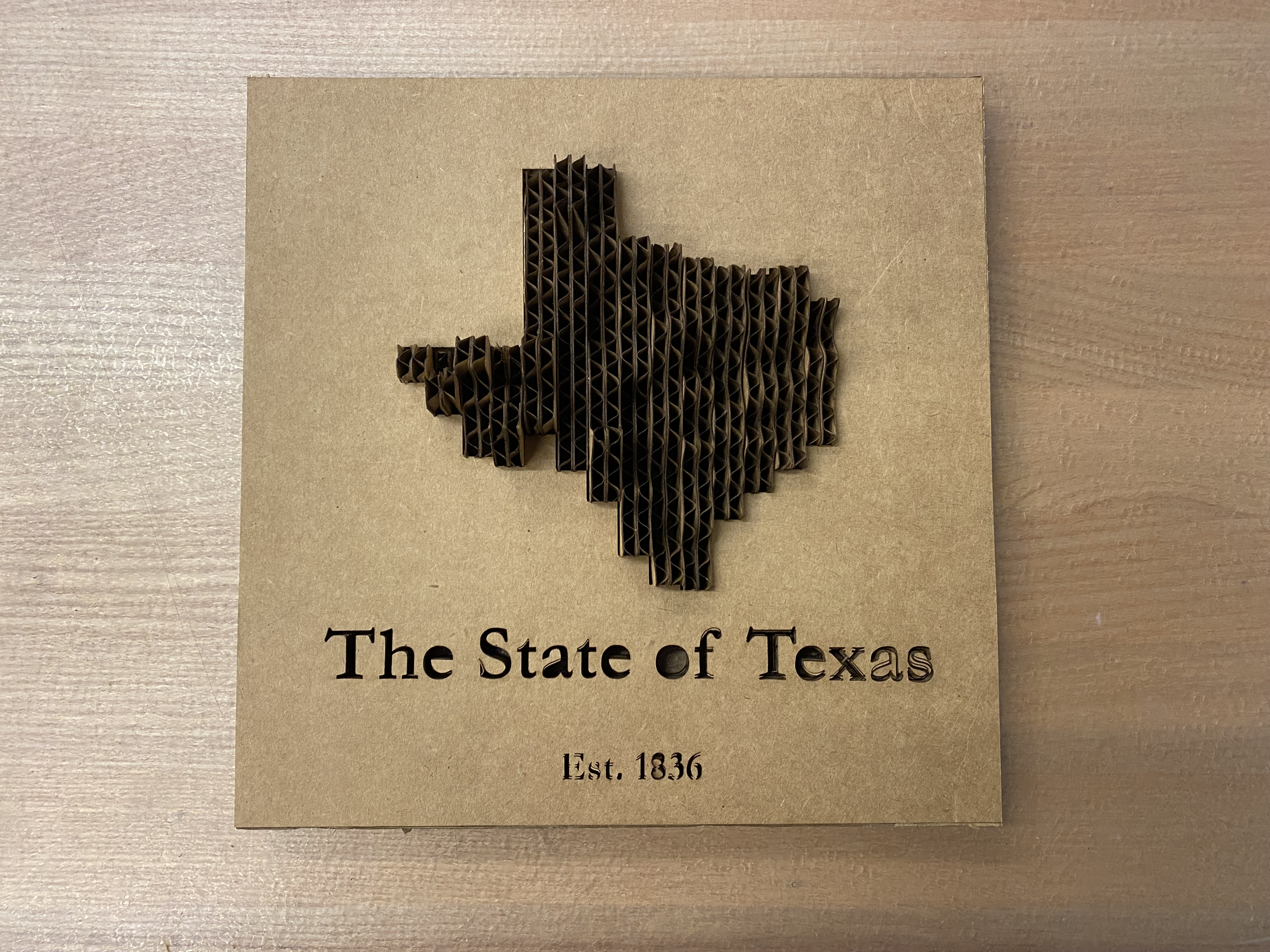
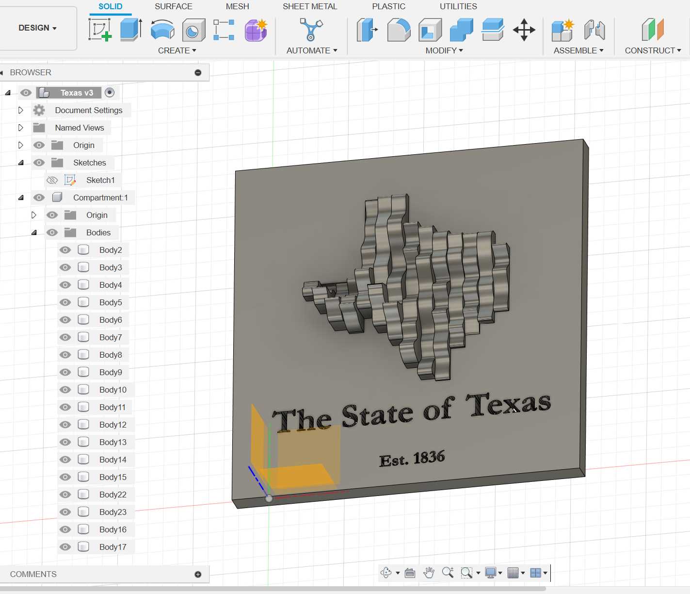
This week, were instructed to "design, lasercut, and document a parametric construction kit." I wanted to make something that was 3D, but I didn't particularly want to deal with making joints, and as I was scrolling thorugh laser cut projects in Google Images I stumbled upon a contour map—perfect!
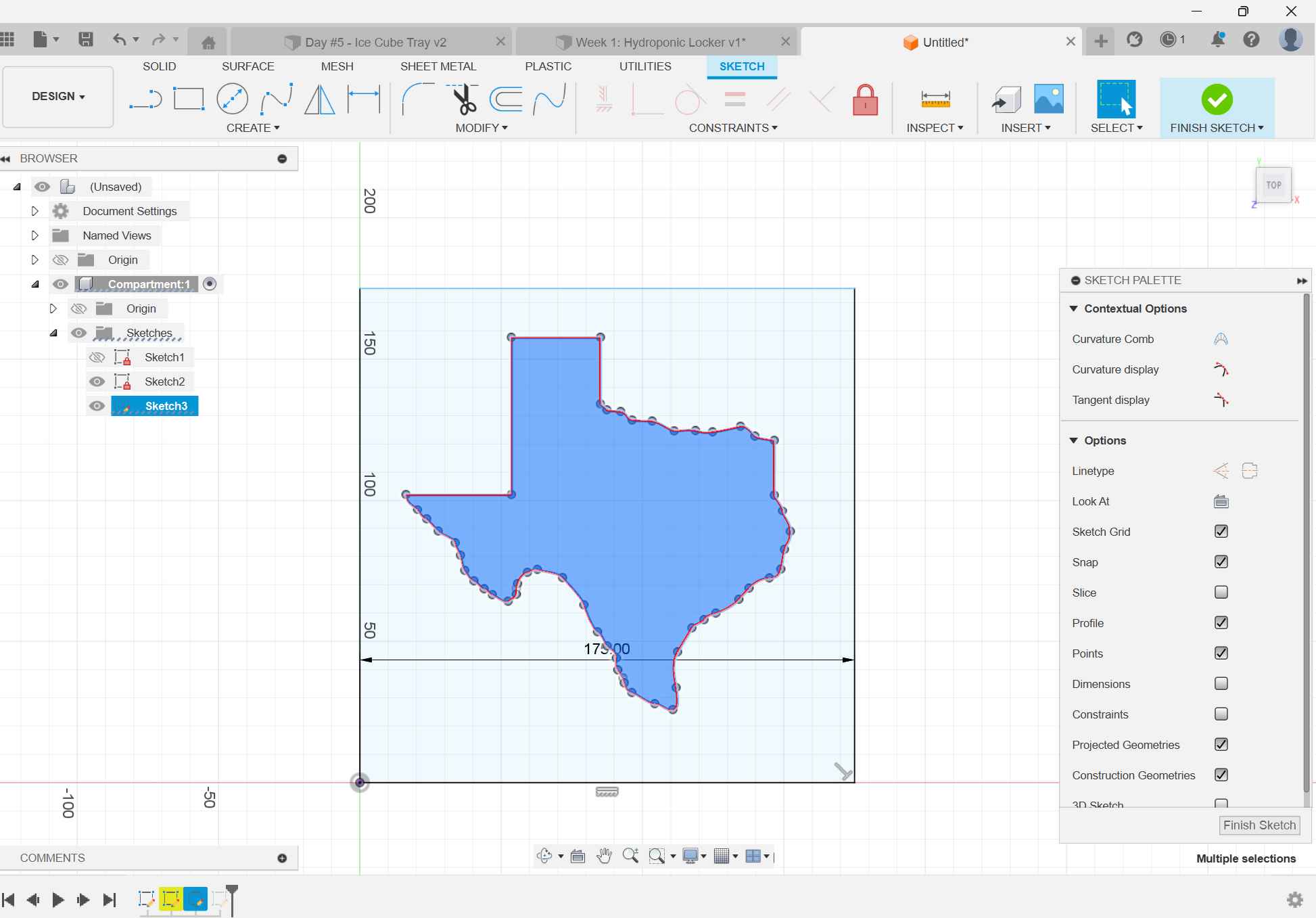
I decided to change things up a bit and try to design the pieces to lay vertically rather than horizontally. I wasn't sure what the exact thickness of the cardboard would be, so the only way to do this was to take advantage of the parametric functionality of Fusion360 and define a parameter for cardboard thickness that I would use for all my measurements.

I initially tried to get the exact topological data for Texas. I created an account with the United States Gelogical Survey, but it turned out to be a lot harder to analyze this data than I thought. In the end, I pulled up the image shown above, and eyeballed the elevations.

With the CAD done, I was able to adjust the cardboard thickness and kerf once I started working with the laser cutter. Luckily for me, it was cardboard which meant that even if the space was just a little bit smaller than the thickness, I could compress the cardboard to make it fit. Because of that, I was able to make it fit first try!
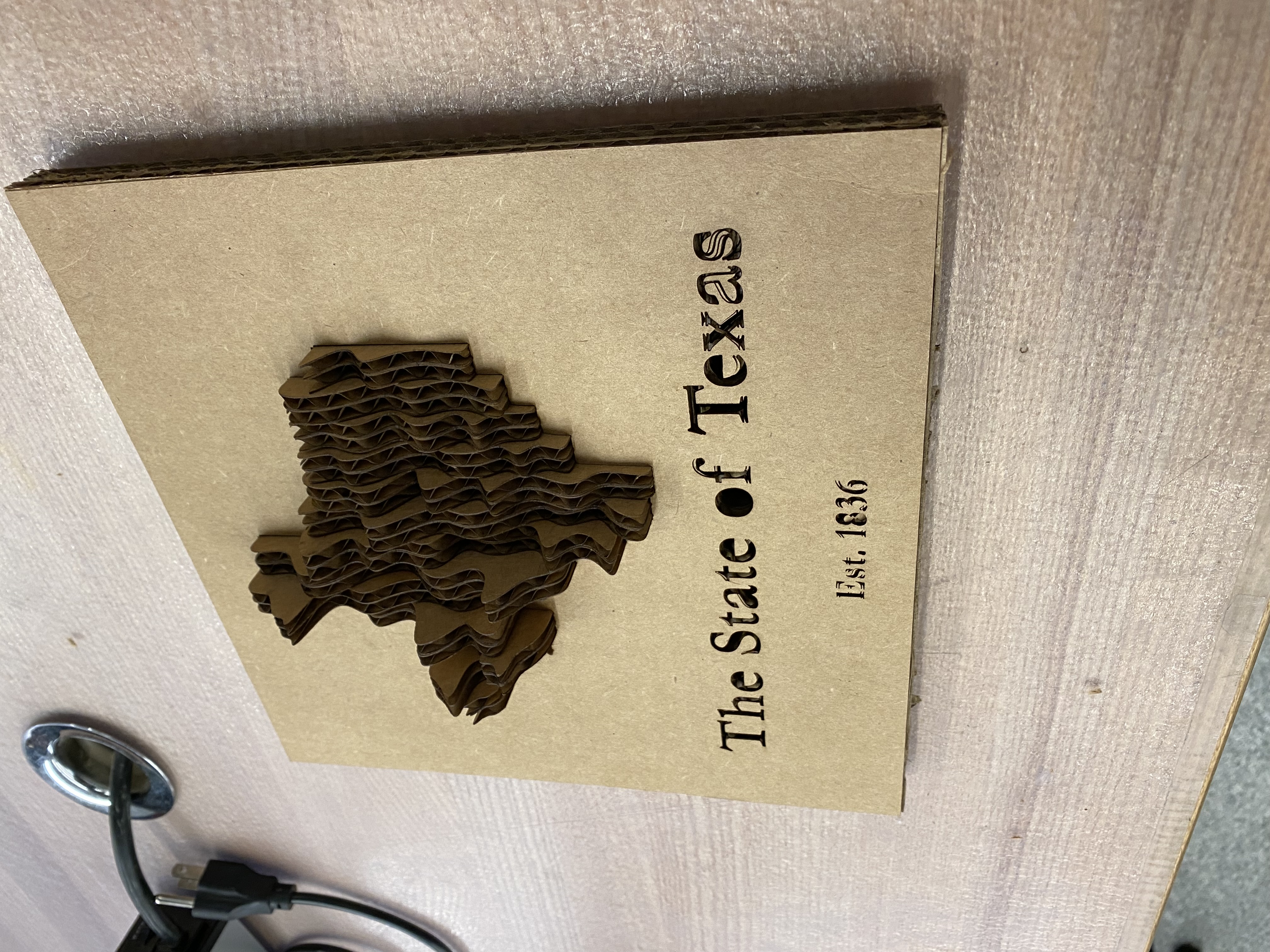
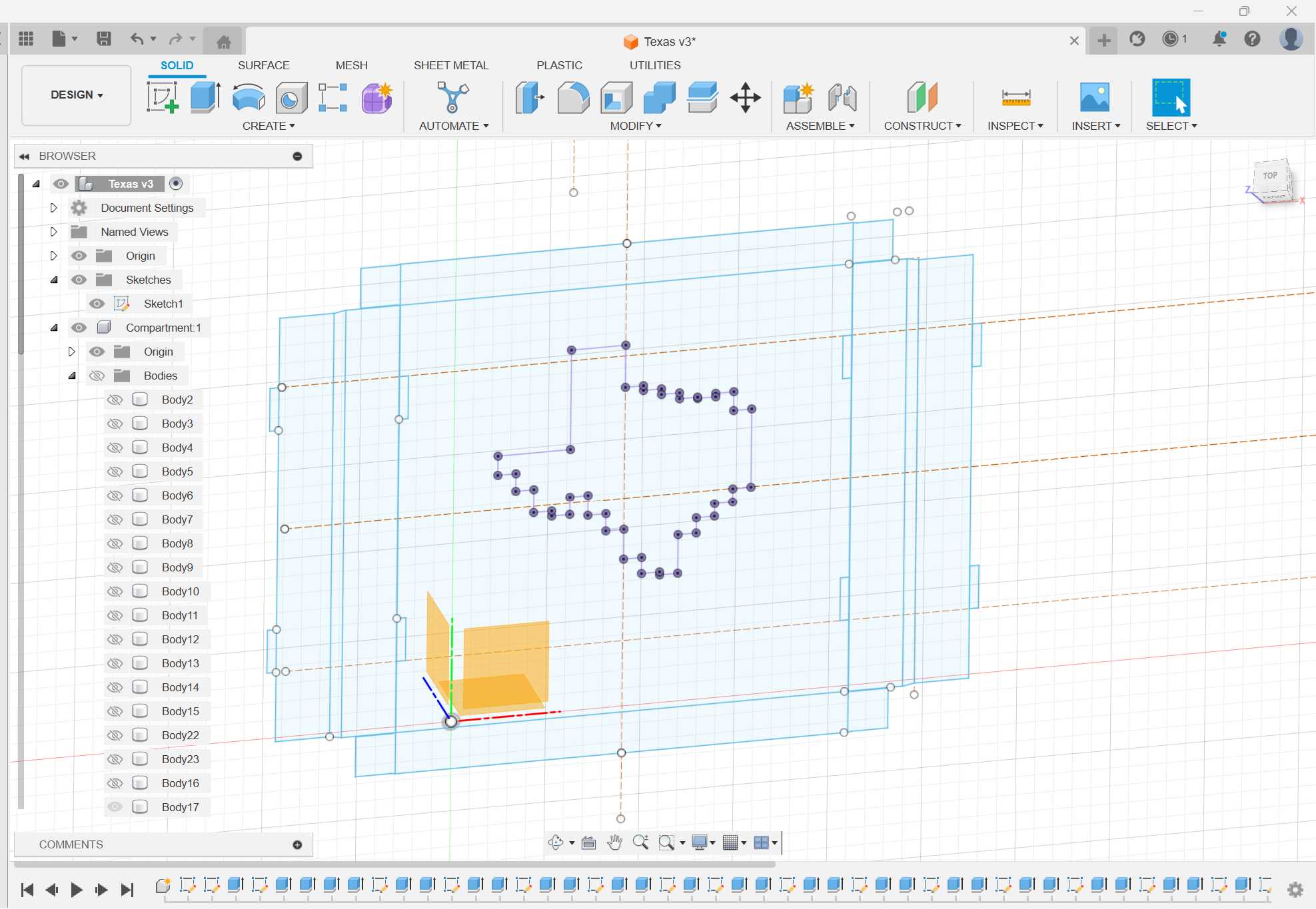
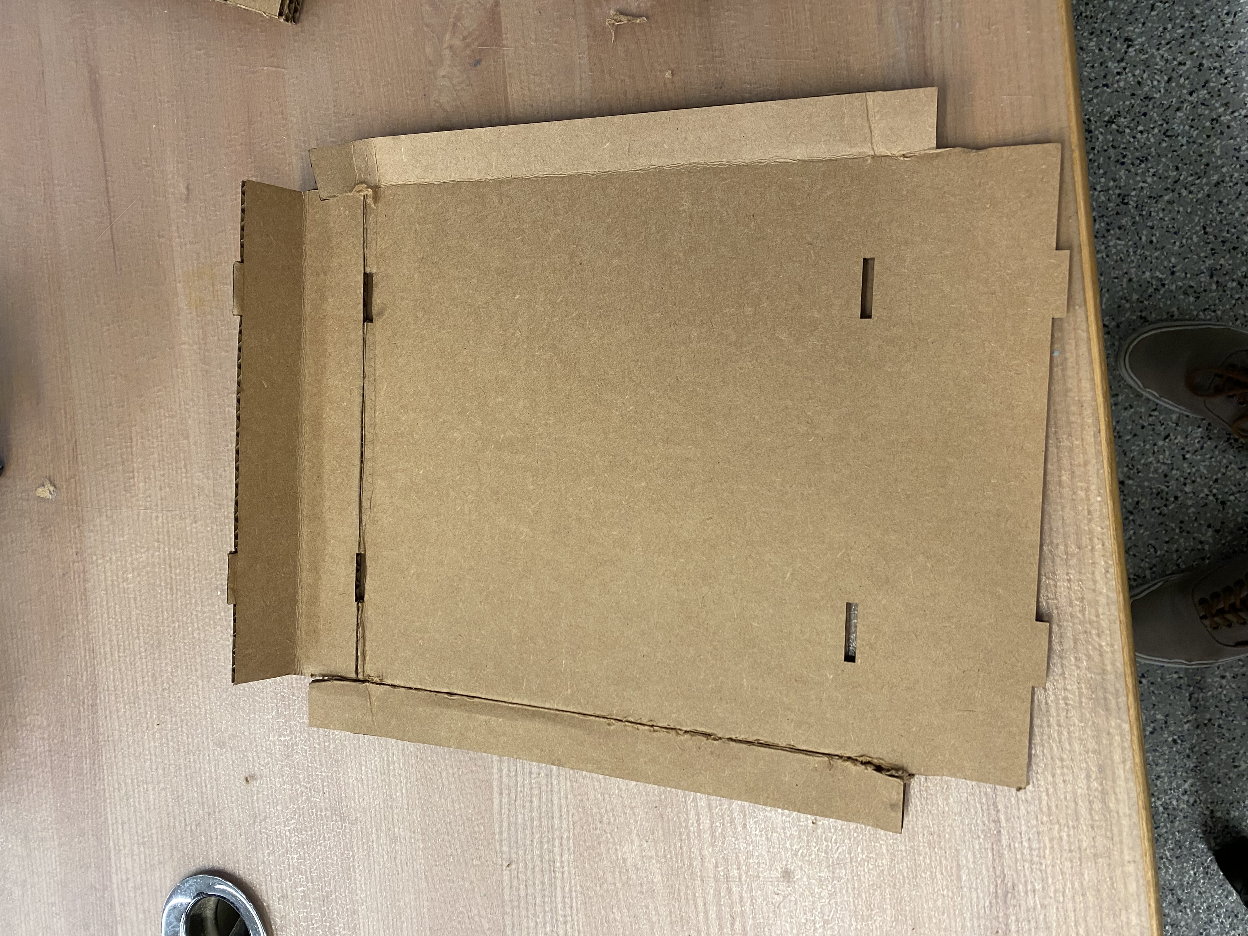
Not everything went according to plan though. On top of the design shown above, I also designed a box to fold around the edges of the square and hold everything in place. After several attempts and more than enough wasted cardboard, I figured the design was sturdy enough to be left as-is.
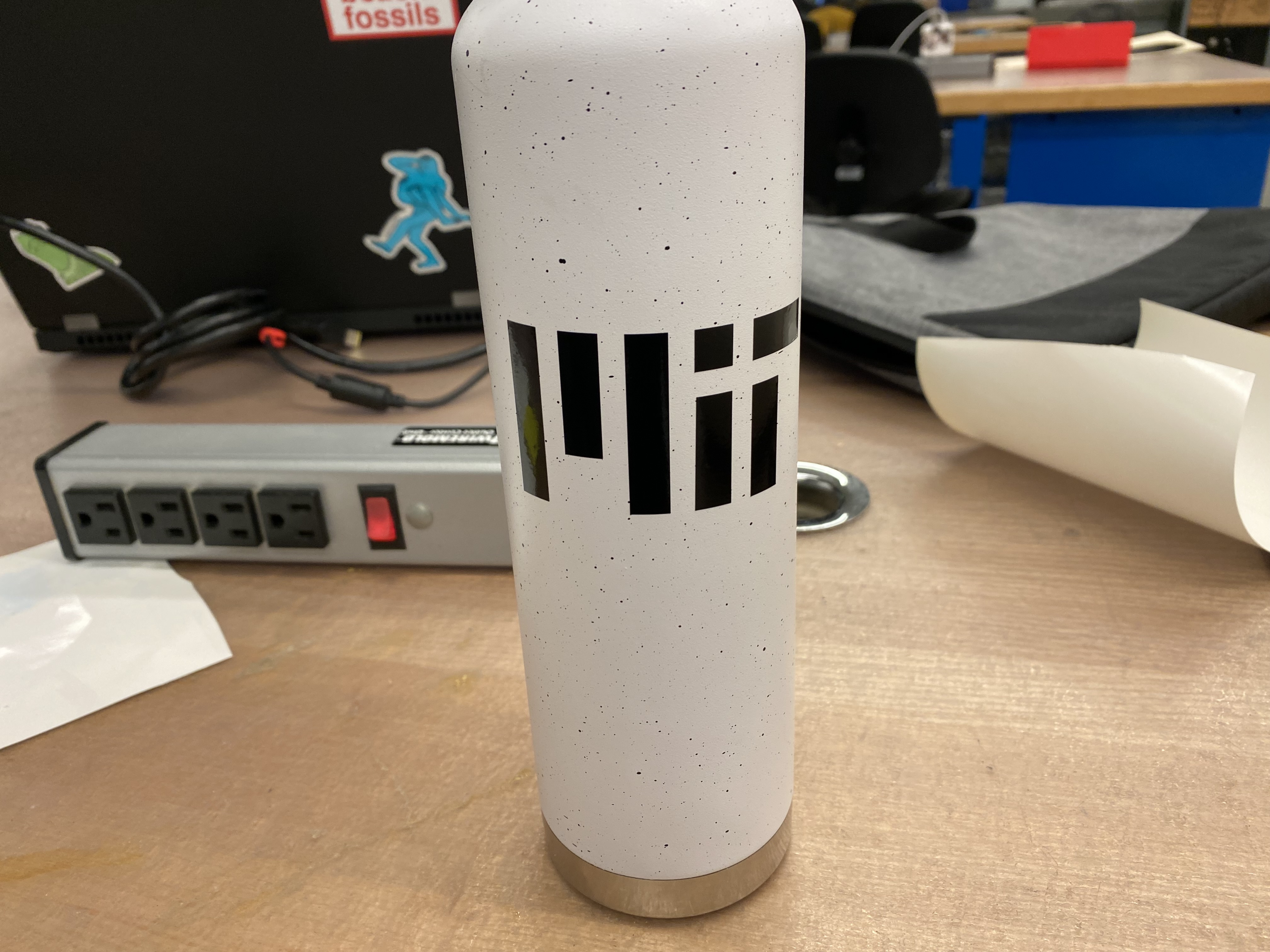
Lastly, I also needed to use the vinyl cutter. I used Neil's mods CE website with the Roland program to generate the toolpaths I needed for the vinyl cutter. I tried a few different designs before I realized how hard it was to work with complex designs so I settled for the simplest logo I could think of: the MIT logo. With the vinyl cut out and ready to go on my water bottle, I carefully placed it on to avoid getting any bubbles, and then I removed the exterior by pulling as low as possible and...it was done! Looks like I was able to save myself $36.98 from The Coop.

If you would like your own Texas sign, you can find my CAD file here.

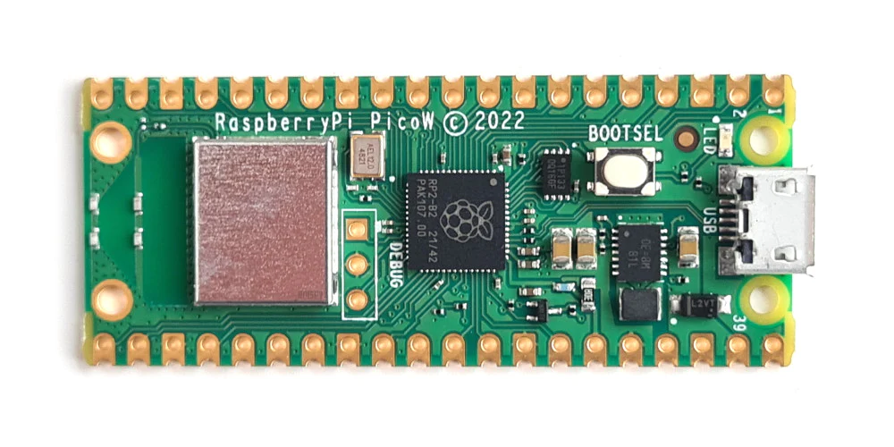
Our task for this week was to write a program for a microcontroller development board to interact with input/output and to communicate remotely. I've worked with ESP32 before, so I thought I'd try something new this week with the RP2040 on the Rasberry Pico W.
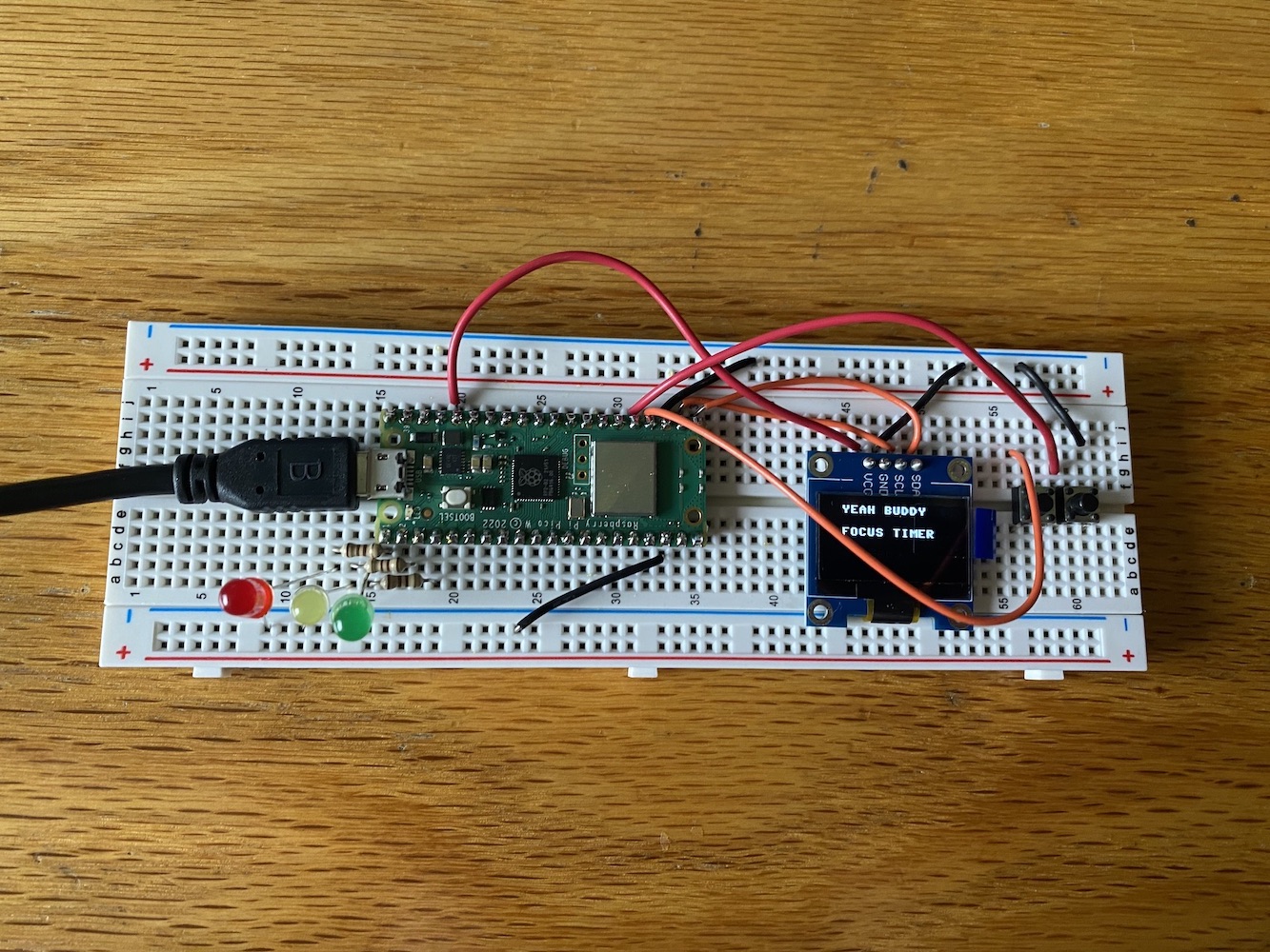
First things first, I took a quick look at the Pico W datasheet. Next, I put some headers on a breadboard with the Pico and soldered them on. Luckily, I am taking 6.200 (Circuits and Electronics) this semsester, and I was able to get some expereince this past week with soldering. Once that was done, I got the Thonny Micropython editor installed on my Mac, I ran through the Pico W Tutorial, and I got the LEDs on my breadboard to turn on and off.
But I wanted to do something more with my Pico. Around campus, it seems that now is right about the time when classes are picking up and people are struggling to stay alive. With that in mind, I thought it would be great to have some kind of tool to help me focus and be more productive in these trying times. I also needed to be realistic and choose a project that would be doable given my limited expereince with Microcontrollers, so I settled on a Pomodoro Timer.
But I wanted something more than a simple timer. Something to inspire and motivate me. So I turned to legendary bodybuilder Ronnie Coleman.
Ronnie is famous for his catchphrases "yeah buddy" and "lightweight" as seen in the following video:
With all this in mind, I started writing the code. Using the OLED display and its corresponding text library, I wrote the functions yeahBuddy() and lightweight() to display the text on the screen and initiate an animation with flashing LEDs. Next, I coded a startup sequence that would count down to 3 and light up the LEDs one by one. Following this sequence, the timer would automatically start by calling a timerSequence funciton for a given number of minutes.
Lastly, I needed a way to adjust the number of minutes for the timer. I used two buttons as input to be able to adjust the number of minutes by increments of 5. Once the adjuster was done, it was just a matter of passing the number of minutes to the timerSequence funciton. Lastly, the microcontroller also to send something back to my Mac. For this, I added another variable to keep track of the overall time that had been spent, and after every session was over, the microcontroller would print this back to my Mac.
And that was it! I wanted to see if there was a way to add some kind of image of Ronnie Coleman using the frame buffer library, but it turned out to be more complicated than I was expecting. At best, some corrupted-looking image would display and at worst nothing would pop up. As I keep working on this in the future, I'll circle back with any updates.
If you would like to see the code for this week, here it is:
from machine import Pin, I2C
from picozero import pico_led, LED, Button
import ssd1306
import utime
from time import sleep
import framebuf
WIDTH = 128
HEIGHT = 64
i2c = I2C(0, scl=Pin(17), sda=Pin(16), freq=200000)
display = ssd1306.SSD1306_I2C(WIDTH, HEIGHT, i2c)
fbuf = framebuf.FrameBuffer(bytearray(100 * 10 * 2), 100, 10, framebuf.RGB565)
currentSelection = True
red = LED(0)
yellow = LED(1)
green = LED(2)
red.off()
yellow.off()
green.off()
fbuf.fill(0)
TotalTime = 0
left = Button(18)
right = Button(19)
def selectionScreen(pastTime):
global add
global minutesSession
def updateScreen(add):
fbuf.fill(0)
fbuf.text("Time:" + str(minutesSession) + " min", 0, 0, 0xffff)
display.blit(fbuf, 10, 25)
fbuf.fill(0)
if add:
fbuf.text(" + 5 min", 10, 0, 0xffff)
else:
fbuf.text("- 5 min", 10, 0, 0xffff)
display.blit(fbuf, 10, 45)
display.show()
minutesSession = 60
add = True
while (not(left.is_pressed and right.is_pressed)):
sleep(0.1)
if left.is_pressed:
if add:
add = False
else:
add = True
if right.is_pressed:
if add:
minutesSession += 5
else:
minutesSession -= 5
updateScreen(add)
fbuf.fill(0)
display.blit(fbuf, 10, 45)
display.show()
timer_sequence(minutesSession)
print("Total time is :", str(pastTime + minutesSession))
selectionScreen(pastTime + minutesSession)
def yeahBuddy():
green.off()
yellow.off()
red.off()
greenOff = True
fbuf.fill(0)
introMessage1 = "Yeeeeeeeeeah"
for i in range(len(introMessage1) + 1):
fbuf.text(introMessage1[0:i], 0, 0, 0xffff)
display.blit(fbuf, 10, 5)
display.show()
if greenOff:
green.on()
yellow.on()
red.on()
greenOff = False
else:
green.off()
yellow.off()
red.off()
greenOff = True
fbuf.fill(0)
introMessage2 = "buddy!!!!!!"
for i in range(len(introMessage2)):
fbuf.text(introMessage2[0:i], 0, 0, 0xffff)
display.blit(fbuf, 10, 25)
display.show()
if greenOff:
green.on()
yellow.on()
red.on()
greenOff = False
else:
green.off()
yellow.off()
red.off()
greenOff = True
fbuf.fill(0)
display.blit(fbuf, 10, 5)
display.blit(fbuf, 10, 25)
display.show()
def lightWeight():
red.on()
yellow.on()
green.on()
fbuf.fill(0)
introMessage1 = "LIGHTWEIGHT!!!"
for i in range(len(introMessage1) + 1):
fbuf.text(introMessage1[0:i], 0, 0, 0xffff)
display.blit(fbuf, 10, 5)
display.show()
fbuf.fill(0)
display.blit(fbuf, 10, 5)
display.show()
sleep(1)
red.off()
yellow.off()
green.off()
def timer_sequence(minutes):
# startup sequence
for i in reversed(range(1, 4)):
if i == 2:
red.on()
if i == 1:
yellow.on()
fbuf.fill(0)
fbuf.text('Ready in: ' + str(i), 0, 0, 0xffff)
display.blit(fbuf, 10, 25)
display.show()
sleep(1)
green.on()
fbuf.fill(0)
fbuf.text('GOOOOOO!!!!', 0, 0, 0xffff)
display.blit(fbuf, 10, 25)
display.show()
sleep(1)
fbuf.fill(0)
display.blit(fbuf, 10, 25)
display.show()
red.off()
yellow.off()
green.off()
minutesCopy = minutes
while (minutes):
minutes -= 1
for i in reversed(range(1, 60)):
fbuf.fill(0)
fbuf.text(str(minutes) + " : " + str(i), 0, 0, 0xffff)
display.blit(fbuf, 40, 25)
display.show()
sleep(1)
display.fill(0)
display.blit(fbuf, 40, 25)
display.show()
yeahBuddy()
lightWeight()
fbuf.text("Sesh: " + str(minutesCopy) + " min", 0, 0, 0xffff)
display.blit(fbuf, 10, 25)
display.show()
sleep(5)
fbuf.fill(0)
display.show()
fbuf.text("Tot: " + str(TotalTime) + " min", 0, 0, 0xffff)
display.blit(fbuf, 10, 25)
display.show()
sleep(5)
fbuf.fill(0)
fbuf.text("RESTARTING...", 0, 0, 0xffff)
display.blit(fbuf, 10, 25)
display.show()
sleep(2)
introMessage1 = "Yeeeeeeeeeah"
for i in range(len(introMessage1) + 1):
fbuf.text(introMessage1[0:i], 0, 0, 0xffff)
display.blit(fbuf, 10, 5)
display.show()
fbuf.fill(0)
introMessage2 = "buddy!!!!!!"
for i in range(len(introMessage2)):
fbuf.text(introMessage2[0:i], 0, 0, 0xffff)
display.blit(fbuf, 10, 25)
display.show()
sleep(1)
fbuf.fill(0)
display.fill(0)
introMessage1 = "Time to"
for i in range(len(introMessage1) + 1):
fbuf.text(introMessage1[0:i], 0, 0, 0xffff)
display.blit(fbuf, 10, 5)
display.show()
fbuf.fill(0)
introMessage2 = "bleeeeed!!!!!!"
for i in range(len(introMessage2)):
fbuf.text(introMessage2[0:i], 0, 0, 0xffff)
display.blit(fbuf, 10, 25)
display.show()
sleep(1)
fbuf.fill(0)
display.fill(0)
introMessage1 = "YEAH BUDDY"
for i in range(len(introMessage1) + 1):
fbuf.text(introMessage1[0:i], 0, 0, 0xffff)
display.blit(fbuf, 15, 5)
display.show()
fbuf.fill(0)
introMessage2 = "FOCUS TIMER"
for i in range(len(introMessage2) + 1):
fbuf.text(introMessage2[0:i], 0, 0, 0xffff)
display.blit(fbuf, 15, 25)
display.show()
fbuf.fill(0)
introMessage2 = "5000"
for i in range(len(introMessage2) + 1):
fbuf.text(introMessage2[0:i], 0, 0, 0xffff)
display.blit(fbuf, 40, 45)
display.show()
fbuf.fill(0)
display.blit(fbuf, 15, 5)
display.blit(fbuf, 15, 25)
display.blit(fbuf, 15, 45)
sleep(2)
selectionScreen(0)
But was I really done with this week? I still hadn't technically communicated between the devices, right?
So with less than a week to go before final projects are due, I realized that I needed an embedded program to be able to control a motor for my pickup winder.
This is outlined more in detail on the Final Project page, but for the purposes of this week, I used an ESP32-C3 XIAO and I needed a way to control a DC motor. Using a MOSFET, I used PWM to control the speed of the motor. TLDR with PWM you can open and close the power supply to the DC motor very, very quickly and control the speed of the robot that way.
I used the Arduino IDE with the code below:
                                            int motor = D0;
                                            const byte numChars = 32;
                                            char receivedChars[numChars];   // an array to store the received data

                                            boolean newData = false;
                                            int currSpeed = 0;

                                            volatile int num_edges = 0;

                                            void cb() {
                                                num_edges += 1;
                                            }

                                            void setup() {
                                                Serial.begin(9600);

                                                pinMode(motor, OUTPUT);
                                                pinMode(D1, INPUT_PULLUP);
                                                attachInterrupt(digitalPinToInterrupt(D1), cb, RISING);

                                            }

                                            void loop() {
                                                // Serial.println(num_edges / 2);
                                                // Serial.println(analogRead(D1));

                                                recvWithEndMarker();
                                                showNewData();
                                            }

                                            void recvWithEndMarker() {
                                                static byte ndx = 0;
                                                char endMarker = '\n';
                                                char rc;

                                                while (Serial.available() > 0 && newData == false) {
                                                    rc = Serial.read();

                                                    if (rc != endMarker) {
                                                        receivedChars[ndx] = rc;
                                                        ndx++;
                                                        if (ndx >= numChars) {
                                                            ndx = numChars - 1;
                                                        }
                                                    }
                                                    else {
                                                        receivedChars[ndx] = '\0'; // terminate the string
                                                        ndx = 0;
                                                        newData = true;
                                                    }
                                                }
                                            }

                                            void showNewData() {
                                                if (newData == true) {
                                                    Serial.print("This just in ... ");
                                                    Serial.println(receivedChars);
                                                    if (strcmp(receivedChars, "+")) {
                                                    if (currSpeed > 0){
                                                        currSpeed = currSpeed - 1;
                                                        analogWrite(motor, currSpeed);
                                                    }
                                                    }
                                                    if (strcmp(receivedChars, "++")) {
                                                    if (currSpeed > 4) {
                                                        currSpeed = currSpeed - 5;
                                                        analogWrite(motor, currSpeed);
                                                    }
                                                    }
                                                    if (strcmp(receivedChars, "--")) {
                                                    if (currSpeed < 251) {
                                                        currSpeed = currSpeed + 5;
                                                        analogWrite(motor, currSpeed);
                                                    }
                                                    }
                                                    if (strcmp(receivedChars, "-")) {
                                                    if (currSpeed < 255) {
                                                        currSpeed = currSpeed + 1;
                                                        analogWrite(motor, currSpeed);
                                                    }
                                                    }
                                                    Serial.println(currSpeed);
                                                    newData = false;
                                                }
                                            }
Aaaaaand I was able to start and stop the motor via the serial monitor on my Mac!

Our task for this week was to design and print a 3D object that could not be made subtractively and to 3D scan something. With this in mind, I decided to come up with a design for slider gloves.
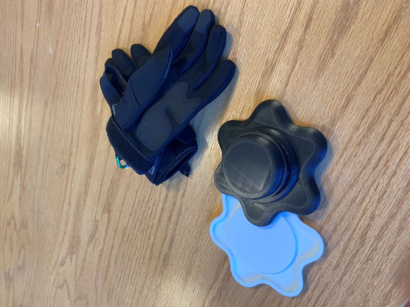
Slider gloves are special gloves with a plastic puck that skateboarders use to make contact with the ground while riding and slide the board to brake or do tricks. I've always wanted a pair to learn how to slide, and I figured this was the perfect opportunity to do so. DIY slider gloves are nothing new. You can find plenty of Youtube videos of people carving out pieces from a cutting board and hot gluing them to a cheap pair of gloves. With access to a 3D printer though, I wanted to improve on this idea by making the pucks replacable so that I wouldn't make to throw out a pair of gloves every time the puck needed replacing.
How would I do this? My idea was to make a permanent base for the gloves that would hold the puck. The base itself would have two interlocking halves that would go across the palm-side fabric of the glove. I didn't know a thing about designing snap-fit enclosures, so I researched on the Formlabs website and went with a basic cantilever joint design. There would be 12 of these "joints", with complementary top and bottom sections, and I made sure to do everything parametrically to be able to accomodate the thickness of any glove. This would mean that I would have to make 12 holes in the glove to lock the parts in place, but hopefully I would never have to do any other work on the gloves except swapping out the pucks. I figured the best way to make the pucks replacable was to make them screw onto the base itself. I researched a bit on 3D printing threads, and it seemed like depending on the printer's tolerance, the threads could get messed up, so I made an extra puck with some added clearance.
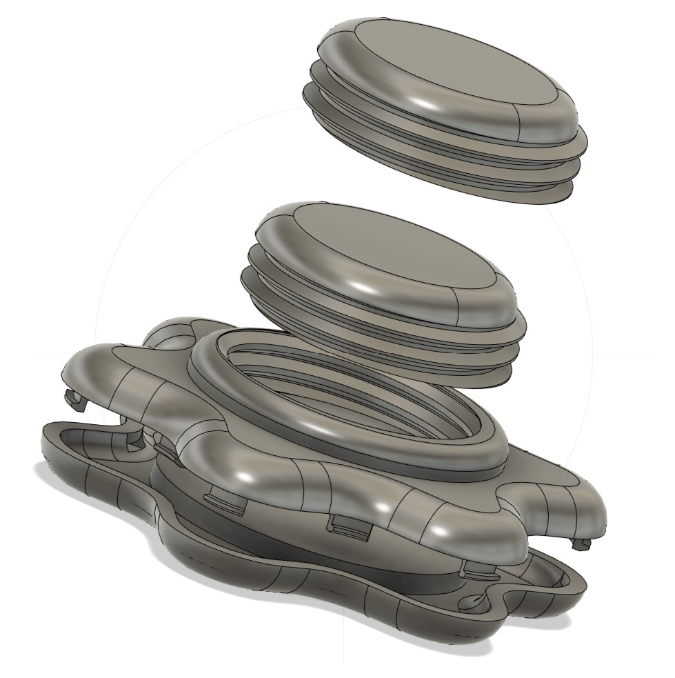
With the design done, I ordered some gloves off of Amazon and got to printing. I chose the Sindoh 3DWOX Printer, put my STL through the slicer, and 12 hours later the print was done! There were a few problems though:
So with all this in mind I made a second version with some updates:
So with the new design down, I went back to the printer for a quick 3-hour print and...there were more problems! It seems that somewhere between the original part and the scaled-down part, I passed the limit for the resolution of the printer, and the cantilever joints were basically nonexistent.
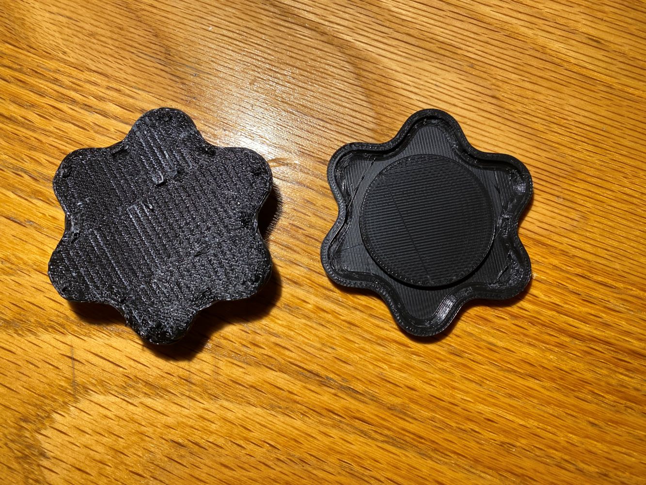
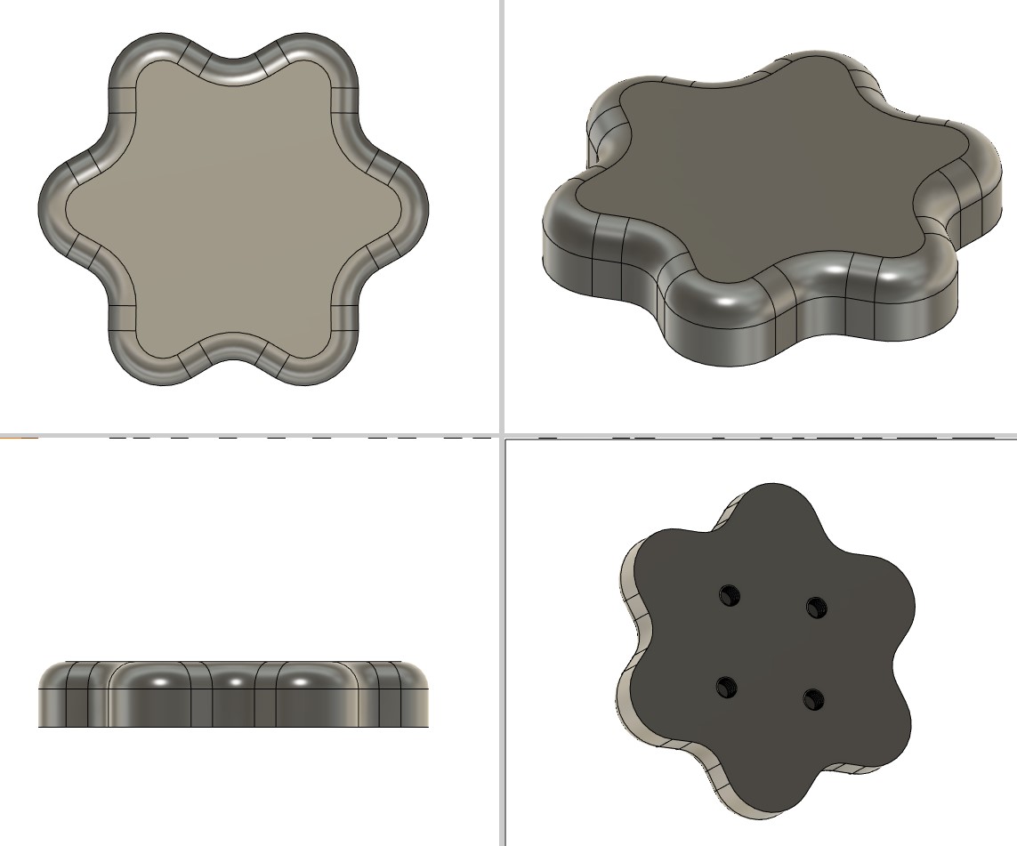
So I again needed another design. I got rid of the bottom plate entirely and just added some threads for bolts to the top plate. I didn't like that the puck was so small on the most recent iteration, so I just extruded the base plate up to become the puck.
With the clock ticking though, I figured it was best to play it safe and opt for the tried and true method to DIY slide gloves: hot glue. I took the two test pucks I'd printed from the original design, lathered them with hot glue, and left them with clamps overnight. The result was a pair of gloves that were good enough to handle my feeble attempts at sliding outside by dorm. That being said, I would expect the puck to scrape off pretty soon, at which point it may be time to revisit my design.
Lastly, for the 3D scannning part of the assignment, I learned how to use the LIDAR sensor/camera at the EDS. I'd brought a Hot Wheels car to scan, but the sensor wasn't liking the reflective finish of the car too much, so I grabbed a 3D-printed gorilla figurine off the desk and scanned that instead. There were still some supports left on the print, which I made it look creepier than expected.
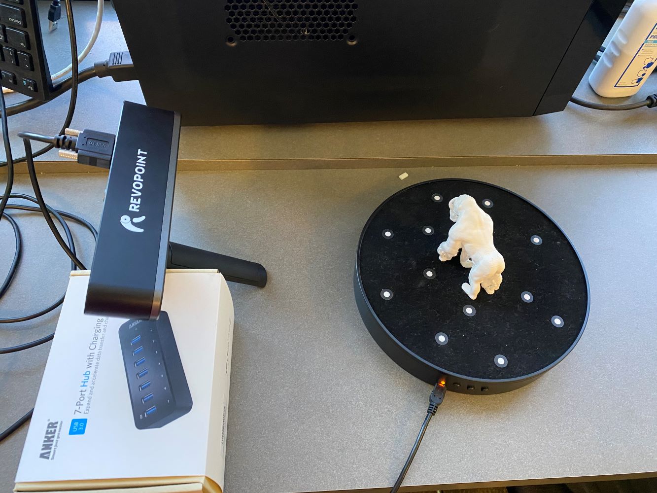
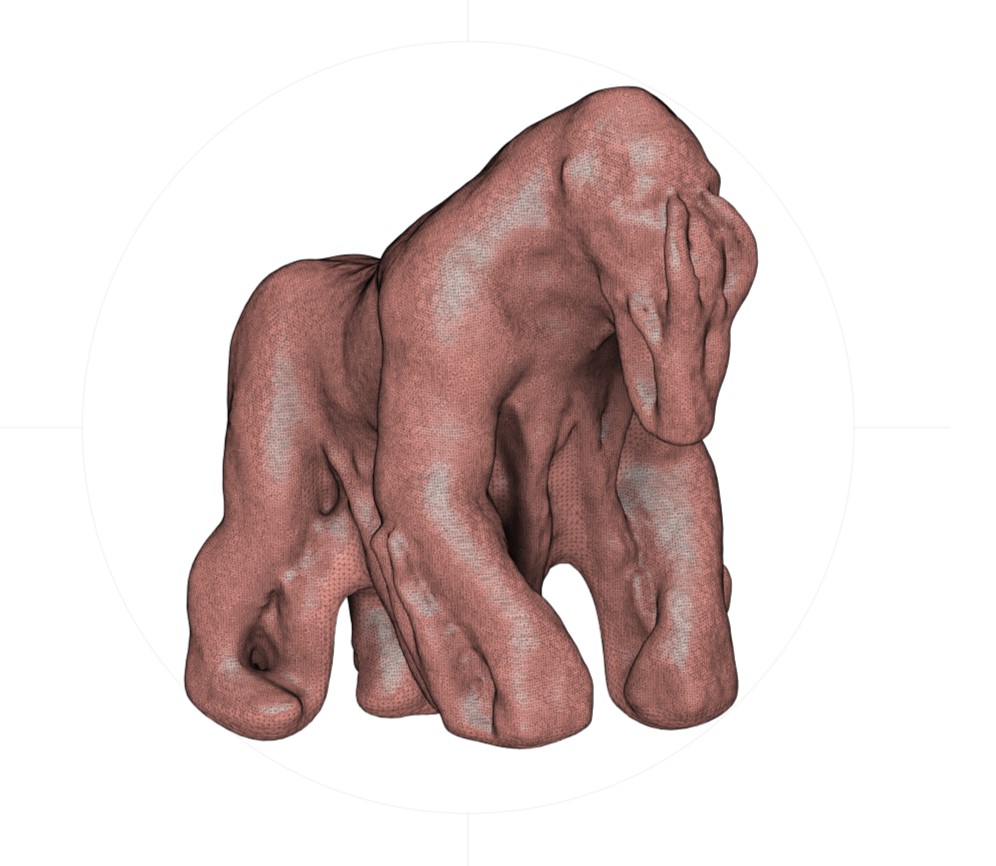
If you are interested in seeing my puck design, you can find it here.

Our task for this week was to use an EDA tool to design a development board to interact and communicate with an embedded microcontroller. I experimented a bit with both EAGLE and KiCad but ultimately went with KiCad because you can use it without being connected to the internet. I was inspired by one of the examples shown in class that made a circuit designed around Neil's face.
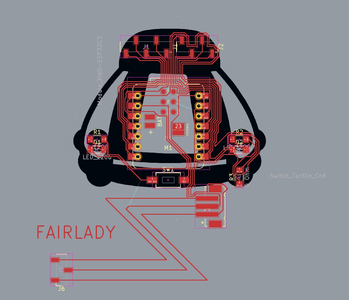
After some brainstorming, I decided that it would be cool to do something creative with the design of my board: to try to model a circuit after a car, with the microcontroller as the engine and with synchonized LEDs as headlights. The car that immediately came to mind was the Datsun 240Z, a car my older brother used to own when I was younger.

I wanted to simplify the Datsun to a duotone design like the example, so I imported a front view of the Datsun, traced the outline, redid the shape a few times to make it look good, and I was left with this design.

With that done, it was time to start the schematic on KiCad. I didn't have any particular functionality in mind of the schematic, so I decided to just make a breakout for as many pins as possible.

That being said, I wasn't entirely sure what would be the best way to wire things up working in the schematic, as my ultimate goal was to try to make the design look like the Datsun, so it took some going back and forth between the schematic and the PCB editor to make everything work. My initial design ended up looking something like this:

...but there were a few things I needed to fix before I go on to the electronics production part of this week.
The main problem was that the PCB layout was not adhering to the design rules that we specified in class. When I started out in EAGLE, this information had come with the class folder, and it completely slipped past my mind to update the design rules when I switched over to KiCad. I also found out that it was possible to convert an image to a board, so I considered the possibility of finishing up my design in Adobe Illustrator or Procreate.
The clock was ticking though, so I decided the best option would be to work with my existing design, redo all the traces to meet the clearance requirements, and mill the board out on the Othermill. I used a 1/32nd and 1/64th and the board came out great! Some of the traces were a little raspy, but with some sandpaper I was able to clean them off in a few seconds:
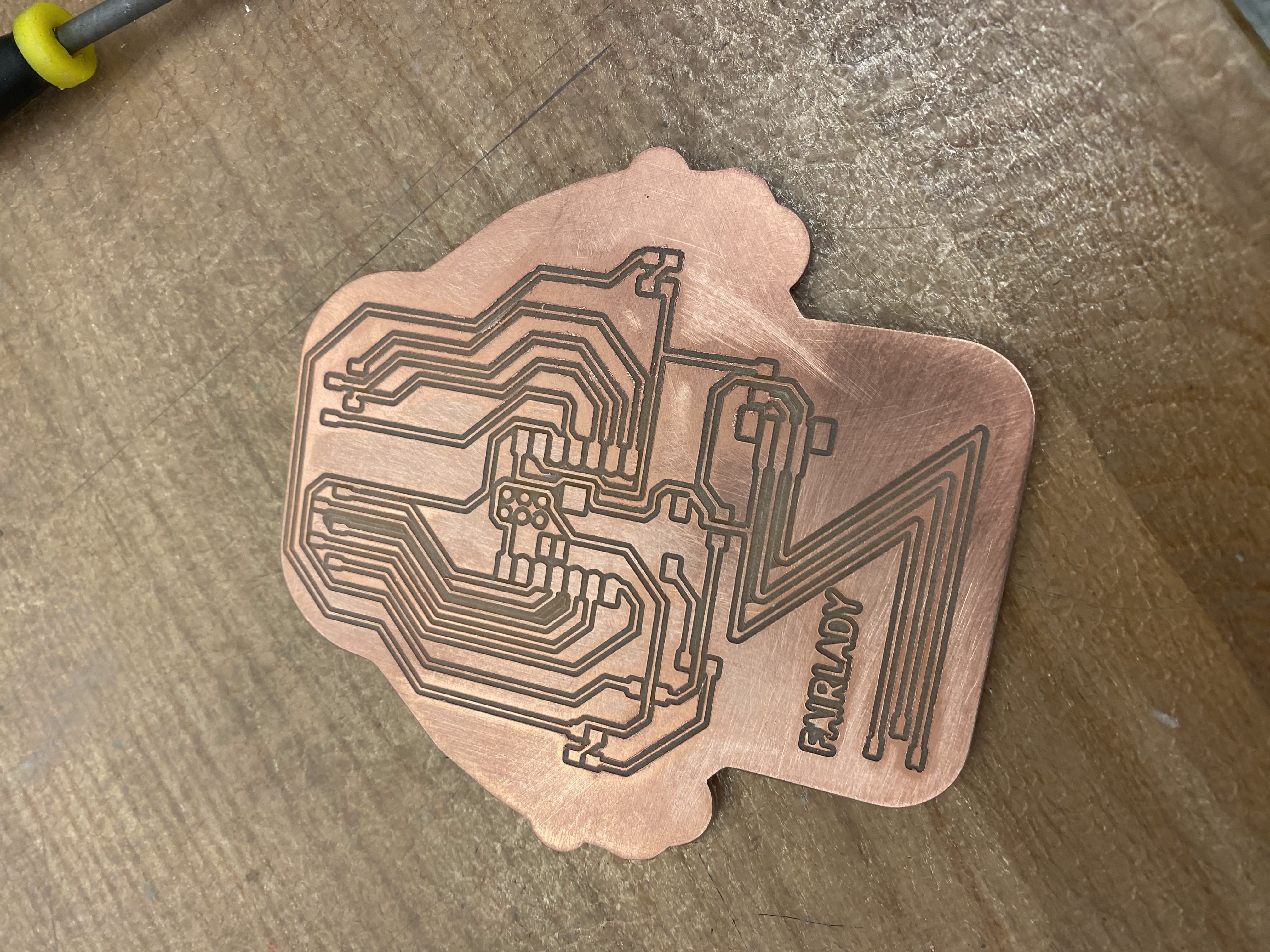
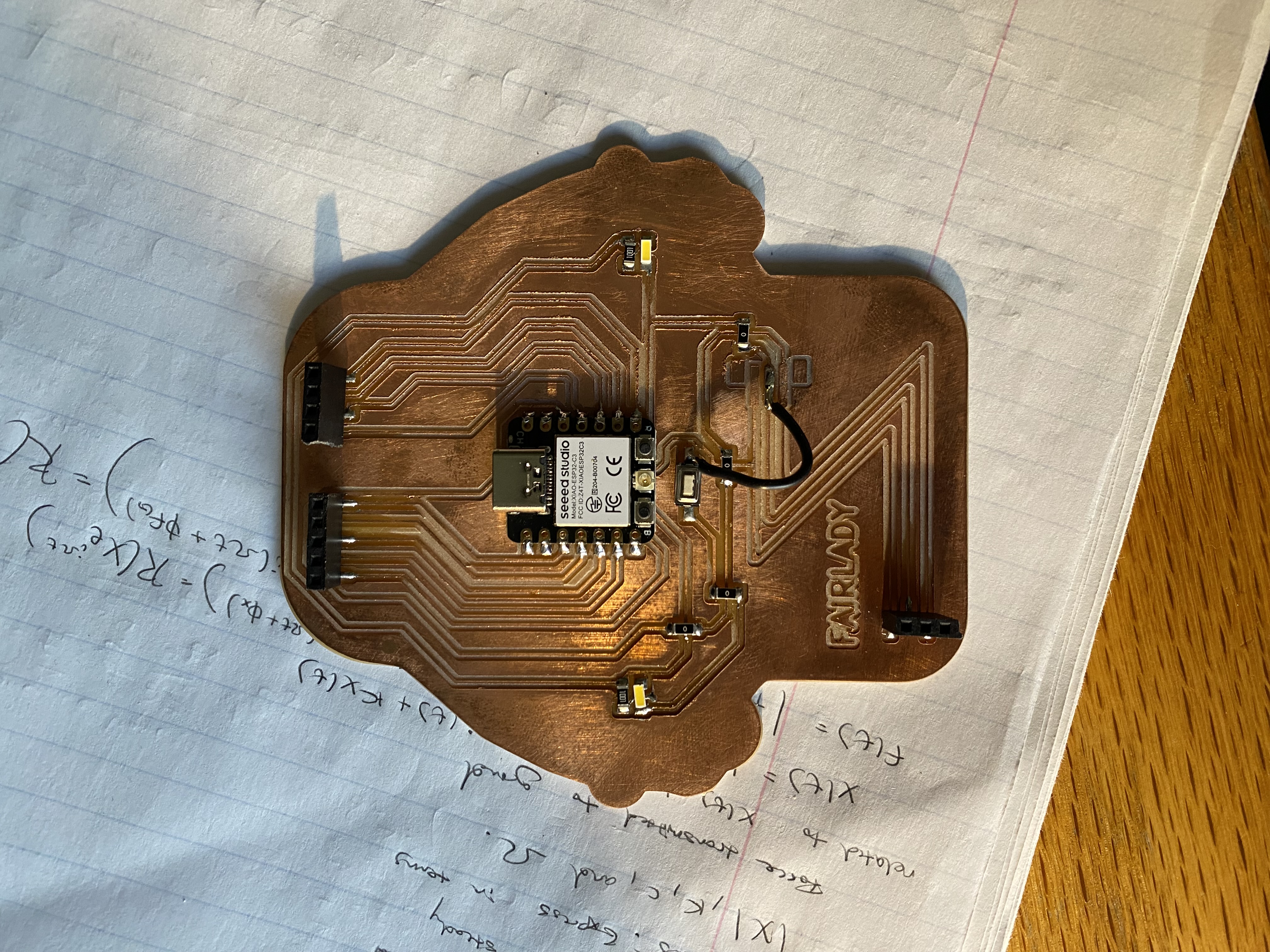
I gathered up all the components and got to work on the soldering. I got some help from Alec with reflow, which helped speed things up for the smaller components on my board. Excited to try out by board, I went back to my dorm, pulled out my connector cable, and...I realized that I had forgotten to think about how I would connect to my board. Out of all the places I could have chosen to place the connectors for voltage and ground (i.e. the only large components in my board design), I'd put them right in front of where I was supposed to plug in the wire to power and talk to the XIAO.
I had to make another board to meet the requirements for this week, so I figured I might as well make the best breakout board I possibly could. I stepped up to the Pico W which meant I'd now be dealing with 40 pins as opposed to the XIAO's meager 14. I got the design done, milled it out on the Othermill again, soldered everything together, aaaaand it worked! I tested it out during input device week, and you can catch a glipse of it in the video I attached at the bottom of that page. But here are both of the finished boards, starting with the Datsun:
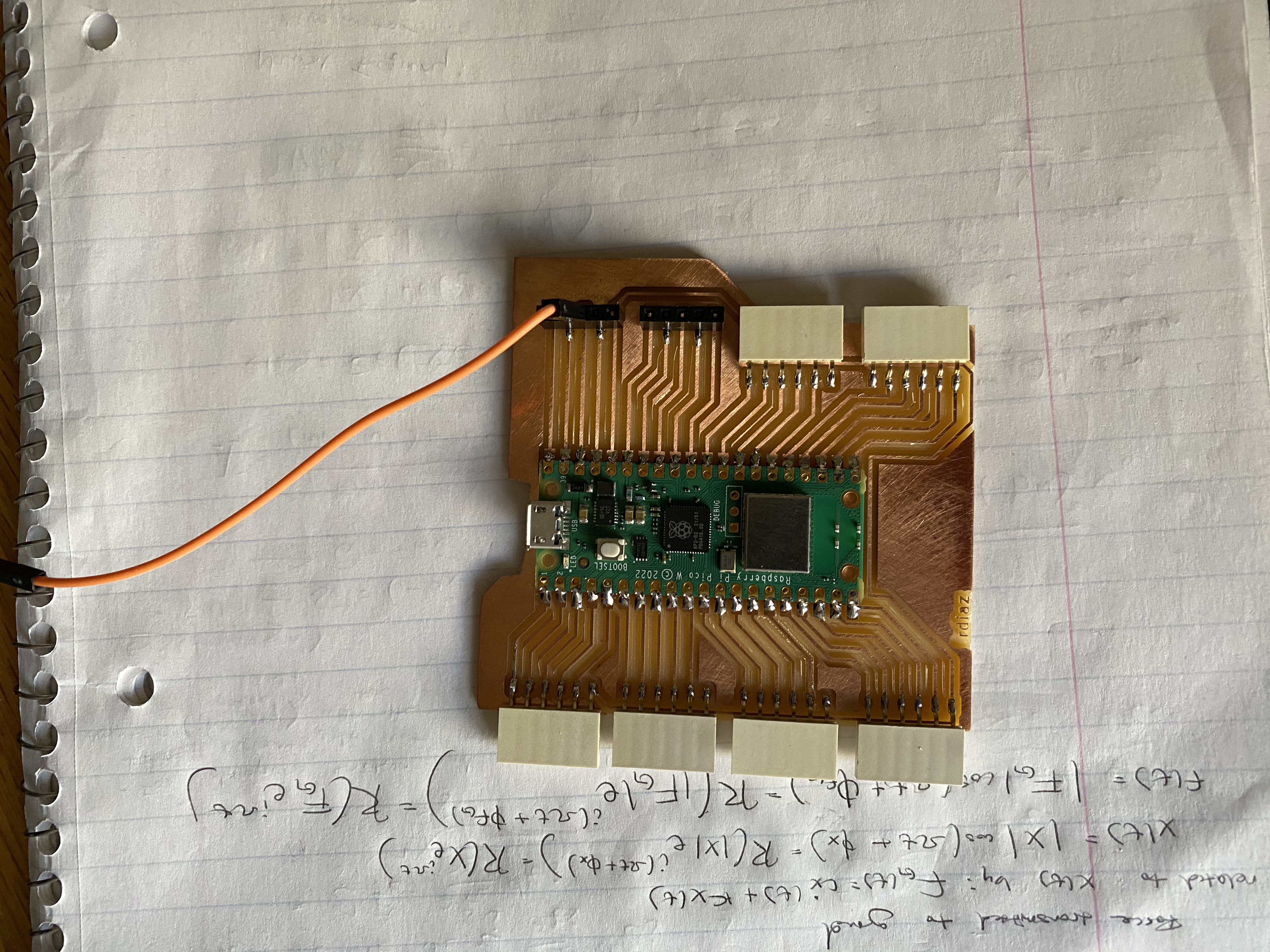
If you'd like to make your own Pico W breakout board, you can find my design here. Besides the Pico, the PCB also uses 6 of these and 4 of these.
Our task for this week was to design a mold around the wax stock we were given, mill it, and use it to cast parts. The moment I heard that we could have the opportunity to make a cast out of metal, my mind immediately went to Iron Man:
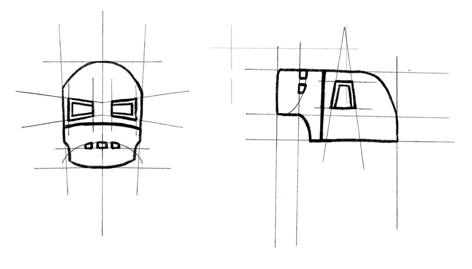
I wanted to make the mask from the original suit from Iron Man 1, one because I thought it looked super cool, but two because it was relatively simple compared to the other suits, and I thought it would be more doable in Fusion360. I started off with some initial sketches in Procreate, just to get an idea of the design that I was going for, and to lay some groundwork for the sketches I would use later on for my CAD. Using some pictures online for reference, I came up with this:

I separated the front and profile view, and imported them into Fusion360 as front and side sketches respectively. I started off by using construction lines to model all of the reference lines that I used in my sketches, and I then used these to create skecthes for the facial features, the front outline, and the side outline. With these sketches done, I then also added some circular rails that connected the front and side outlines and I lofted the two of them together. Getting the facial features to project exactly on the curved surface was a lot tricker than I expeced, but after some digging on Youtube, I was able to project the sketches onto a body, split the body from the mask, and then separate the two. I made the back of the helmet as well, following a similar process as before with the front and side profiles, rails, and the loft feature.
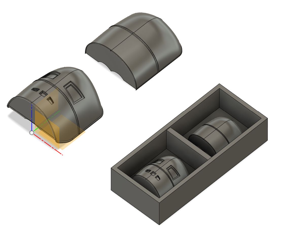
With that done, it was onto the CAM. With a lot of help from Anthony, I was able to get the CAM for my design and after about 45 minutes of running the wax stock through the CNC, the wax positive was done! From there, I washed the part, measured out the oomoo and did my first silicone cast. The back mold ended up looking amazing, but the front mold was filled with bubbles, so I redid the front mold, making sure to work as quickly as possible to keep the material from solidifying. The mold turned out much better the second time around, so I mixed up some hydrostone, poured it into my oomoo casts and...the mask was done!
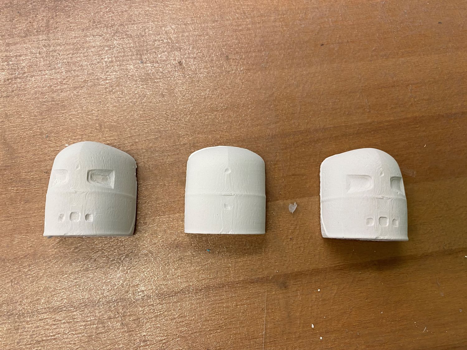
I wanted the front and back portions to stick together, so I took some hydrostone again and lathered it onto the back of the mask like a layer of peanut butter and left the two parts held together with rubber bands overnight. I checked it out the next day, and it definitely did the trick! Lastly, if you are interested, you can find my Iron Man mask CAD here.
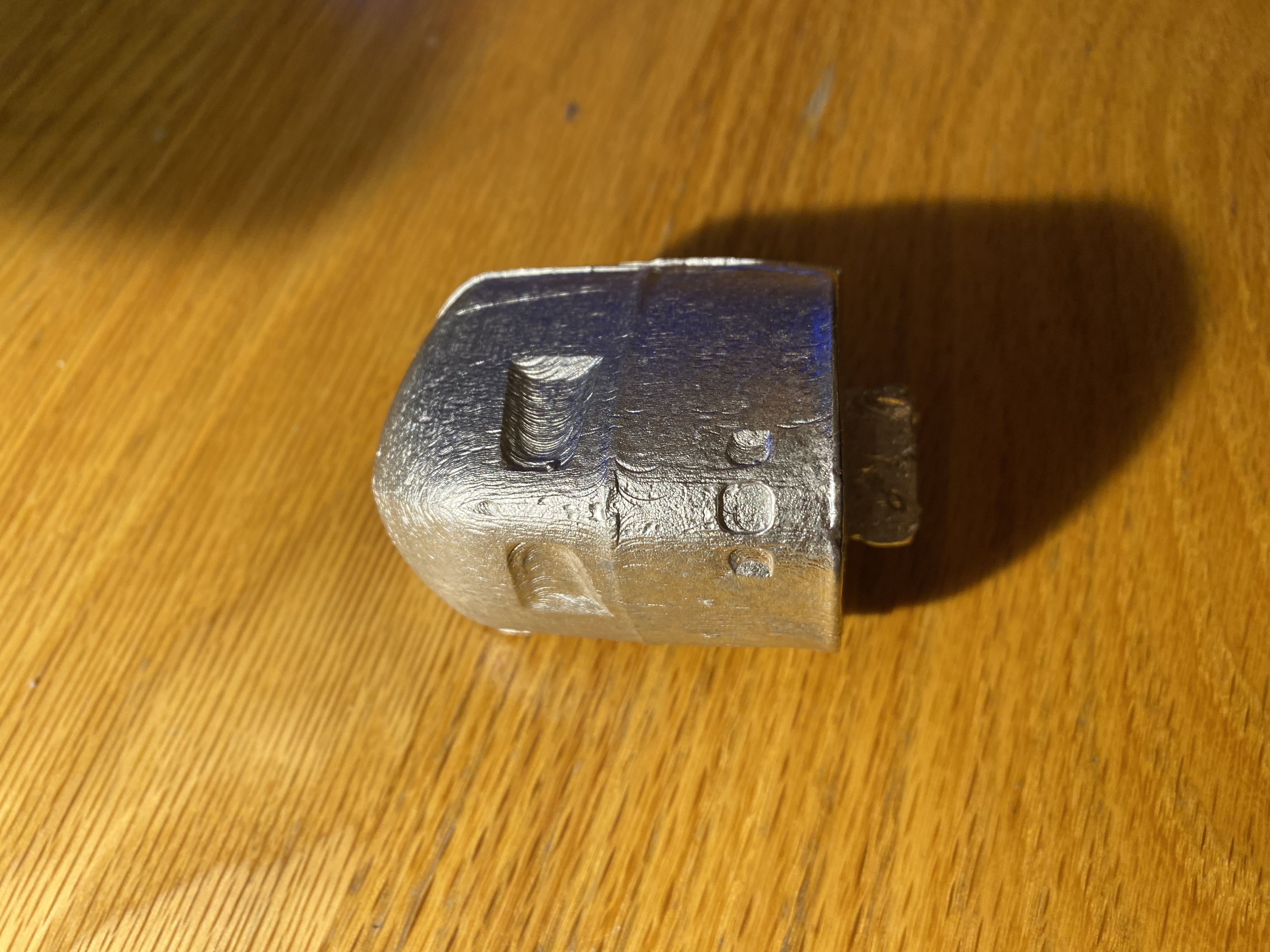
And a few weeks later, I'm back! With Friday off for Veterans Day, it was finally time to make the Iron Man mask out of Roto 281. As the name suggests, Roto 281 melts at 281 degrees Fahrenheit, so it can be melted by sticking some crucibles into a toaster oven and it won't melt the silicone oomoo molds. That being said, it is still pretty dense--something I didn't realize until I pulled the metal out of my mold and saw that Iron Man's mask was a little more narrow than I expected:
This week, our assignment was to make something BIG. In terms of materials, we would be getting a 48" by 48" sheet of OSB to work with, and we would mill out the part with a CNC. As extra credit, our design would require no screws/fasteners/glue, and I figured it was worth a shot.
I wanted to make something useful for my dorm, and I thought my current setup for scanning film negatives could use some work:
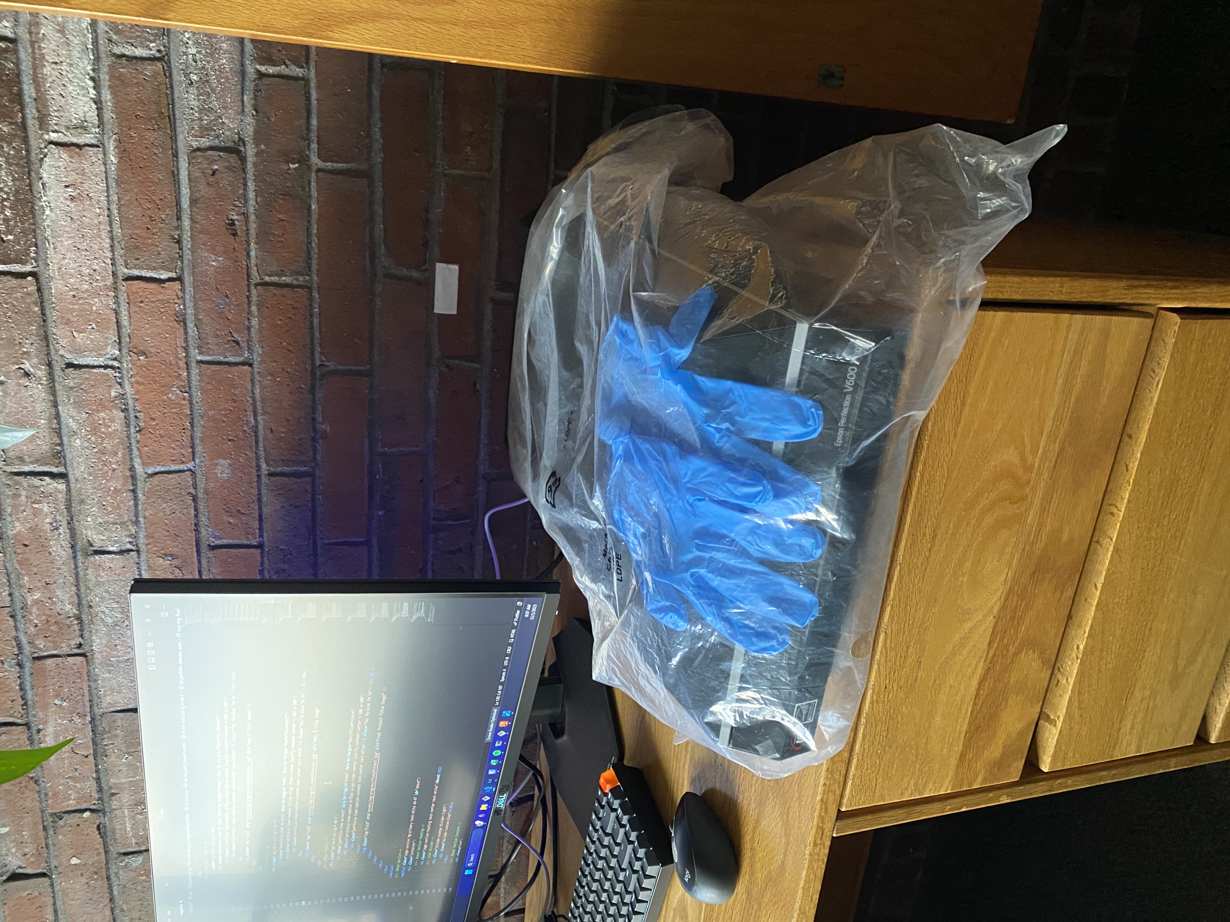
Outside of classes, I do film photography and I scan all my negatives with my trusty flatbed Epson V600 scanner. Right now I just have my flatbed on my desk, but there are at least a few problems with this:
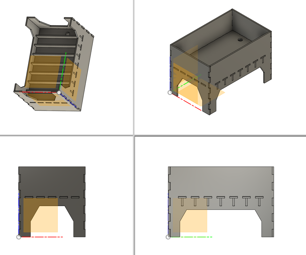
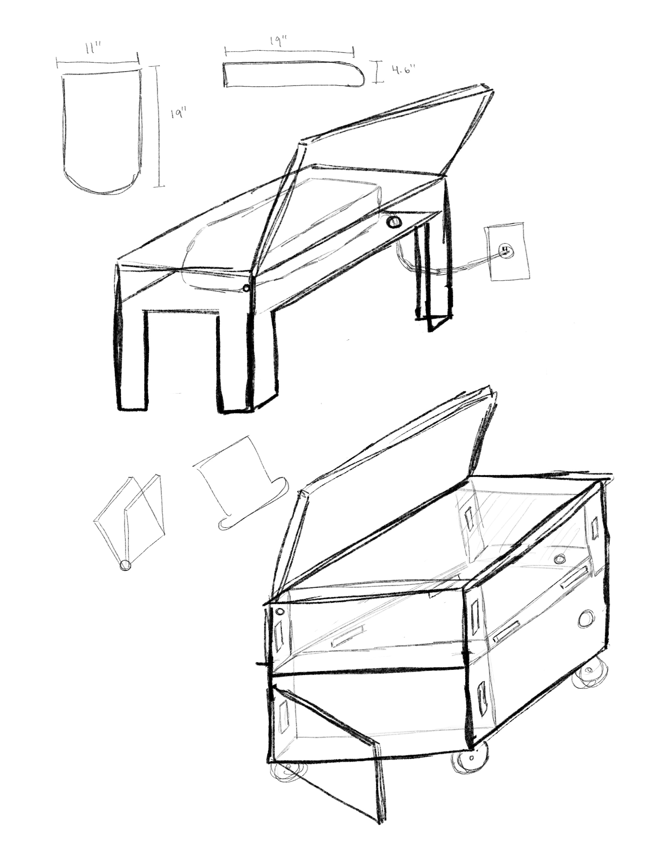
With this in mind, I started sketching out the design for the scanner-holder. I initially took inspiration from the furniture designs at a company called Opendesk that were showed during class to design the hinge shown below, but after talking it over with Anthony it seemed like OSB rubbing against OSB wouldn't be the best idea if I wanted to reduce dust. With that in mind, I adjusted my design to instead just have a cover that I could easily pop off and on into some slots on the top edges. The big thing with making the joints fit together was parametric design. All this really meant was taking advantage of the parameters feature in Fusion360 (found in Modify->Change Parameters), and making sure that I could easily adjust the clearances of the edges of the design to account for the runout on the machine. I ran through a few designs over the course of a couple of days until settling on the design below, and ultimately overlooked the parametric design aspect of the project.
I showed up to my time-slot for the CNC machine, and I quickly realized that the thickness of the OSB in my design was incorrect. No problem, I thought, I'll just change the parameter. As I soon found out though, my design was not as parametric as I thought. I did some quick adjustments to try to at least get something I could work with, and I trusted that whatever imperfections were left could be solved with a lot of time and a file. With Anthony guiding me through the process, I nailed the board down to the base of the CNC with a plastic nail gun, got the trace cut G Code files onto the machine, loaded the endmill, zeroed the axes, and watched as the CNC machine got to work.
Around an hour later, the machine was done and I had some tabs to remove. I used an oscillating power-saw to cut off all the tabs and get the individual pieces from my design. From there, I got to work with the file and managed to get the front and back to stick to the base of the design:
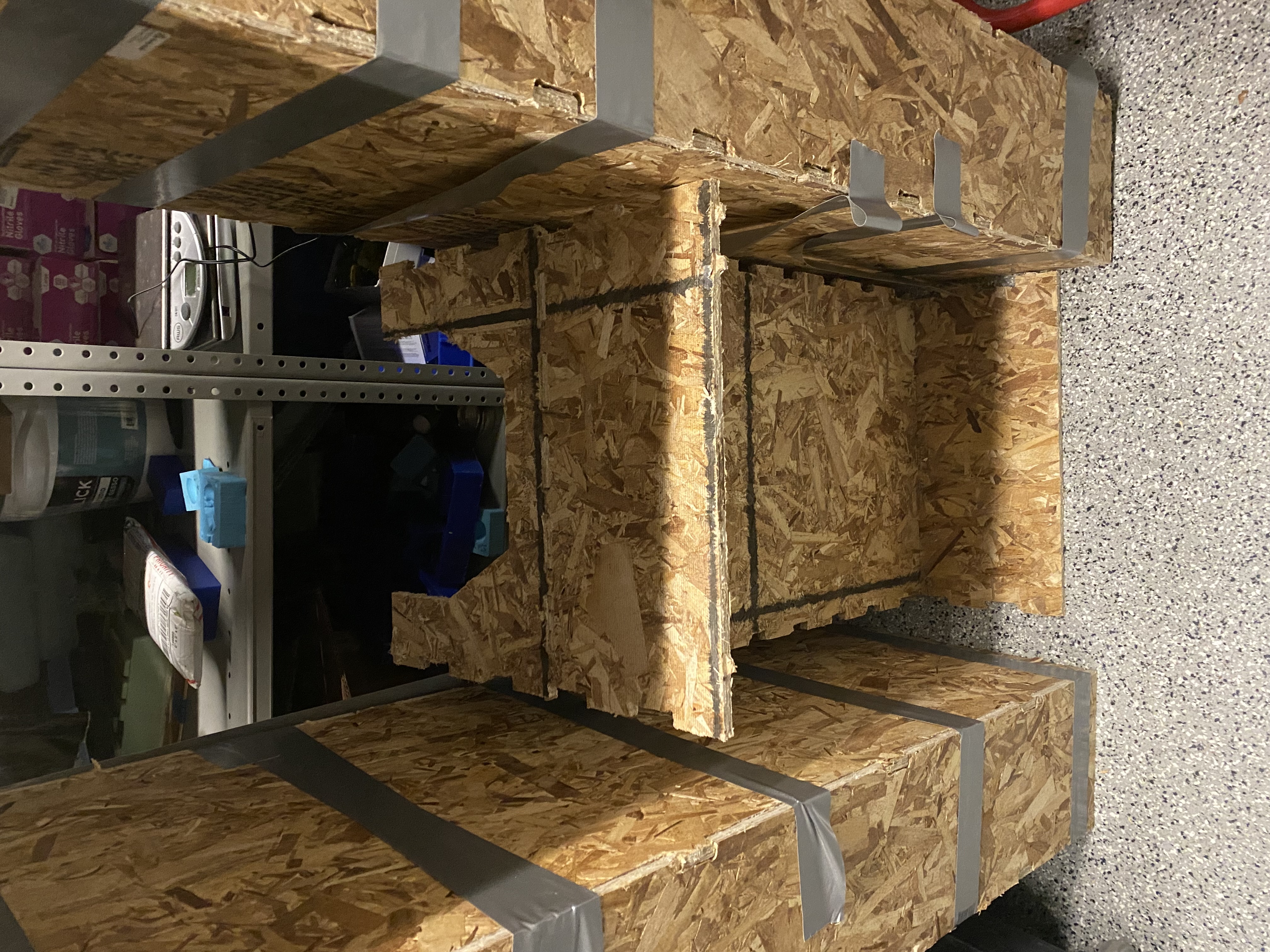
With some more filing, I could make the other two parts fit, but I realized that Anthony was right: there was way too much dust to feasibly make this a stand for my scanner. With that in mind, I got to work on another improved design that would not feature as many joints, and which I could potentially cut on some nicer plywood. Time inevitably ran out and I was a little hesitant to bike over to Home Depot to pick up a 48" by 48" piece of plywood so, for now I just have the here for download. Note that the hinges can be found here.
This week, our assignment was to "meaure something"; i.e. add a sensor to our microcontroller board and read the signal. My idea for this week was to make a light meter.
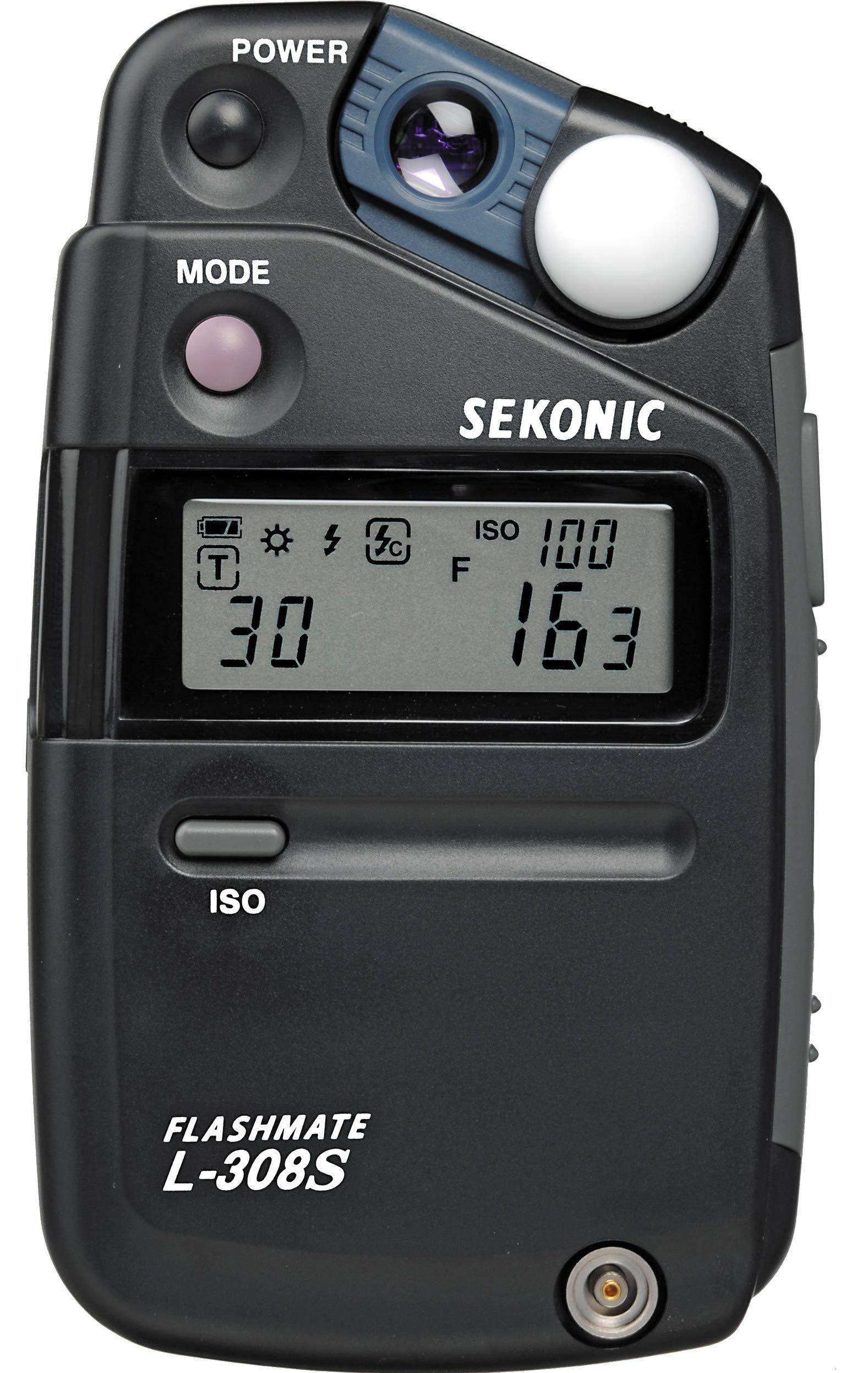
Light meters are used in photography to know how camera settings should be adjusted to get a properly exposed image. All cameras have some sort of light sensor, and depending on how bright a particular scene is, you'll have to either allow more or less light to reach the camera sensor.
The relationship between luminance (what the light meter senses) and the exposure value (what the camera uses to adjust settings) is given by \(EV = log_2(ES/C)\), where EV is exposure value, E is luminance, S is the ISO of the camera (fixed on film stocks used in SLR film cameras), and C is a calibration constant.
A good handheld light meter can run you upwards of around $150, so I wanted to see if I could make a decent knock-off with the light sensors we were given this week.
I thought it would be good to get a variety of ranges for the luminance measurements, so I went with a 940nm infrared phototransistor and an RGB sensor. This week I also redid my board from electronics production week (after the significant design oversight in my original board), so I had a Rasberry Pico W breakout board to work with.
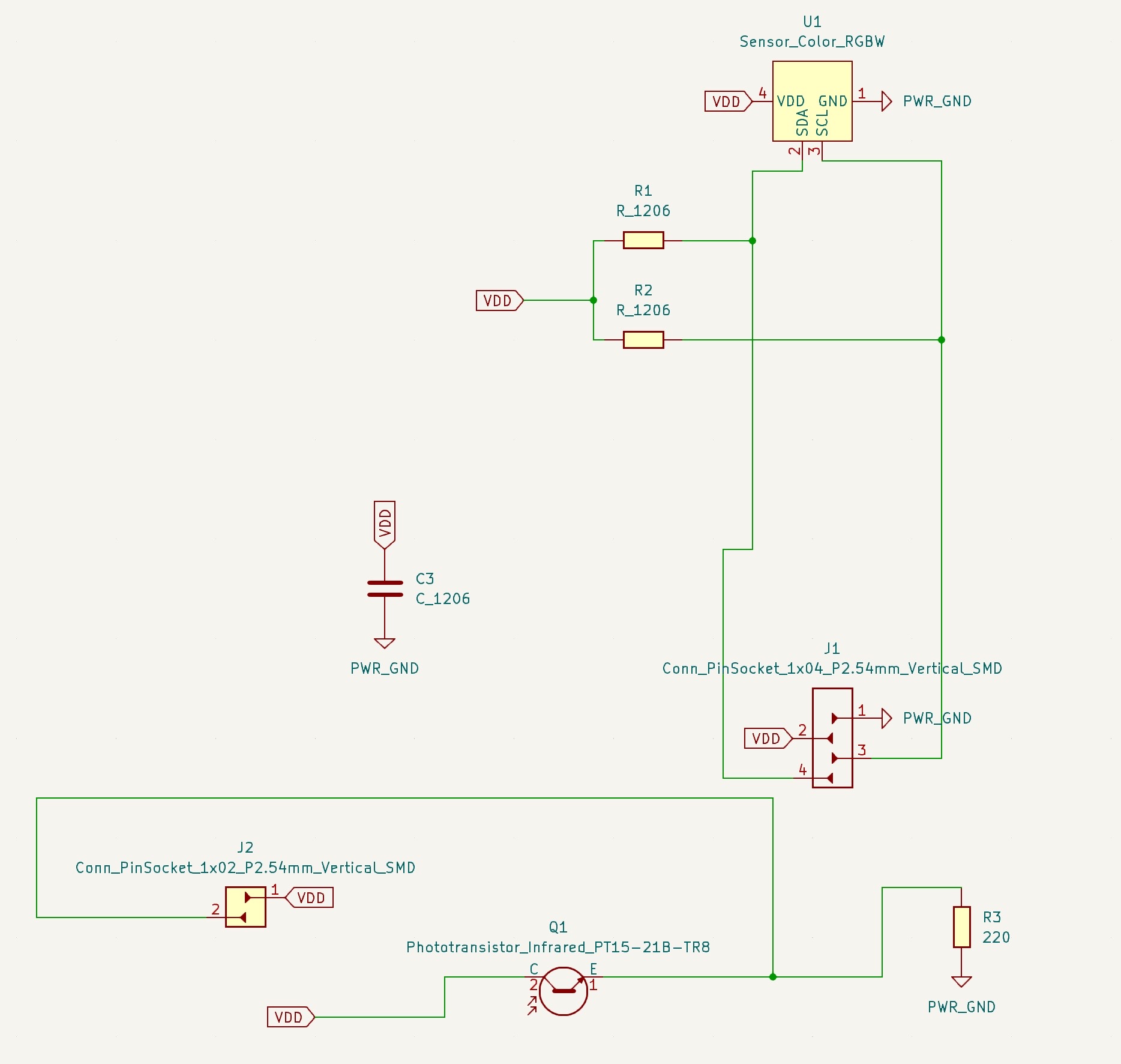
First step as always was schematic and PCB design in KiCad! The schematic was relatively straghtworward after taking a good look at the datasheets for both devices. The RBG sensor required two pull-up resistors along with a capacitor for "power supply rejection", and the phototransistor needed a current-limiting resistor to not fry itself with the voltage from the pin. Moving on to the PCB design, it was just a matter of getting all the connections down. As it turns out, the RGB sensor had a very, very, very small footprint, so it took a bit of footprint adjustment with Anthony to get the clearance big enough to be able to mill it out.
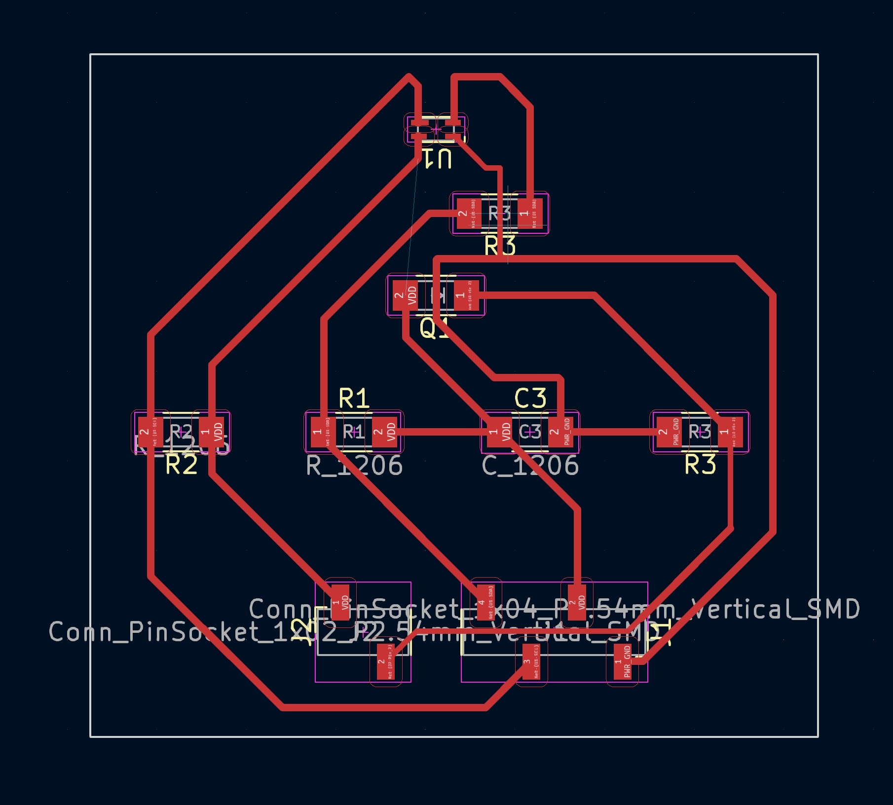
And here the problems began...
I decided to use this week to also learn how to use another CNC router. It didn't seem to have a name/brand associated with it so I'll call it the one in the plastic case in back. I used Quentin's gerber2img converter to turn my gerber files into high-resolution PNGs, opened up Neil's mods website, selected programs->open program->mill 2D PCB, and got the G Code for the traces (cut with 1/64th) and the edge cuts (cut with 1/32nd). I grabbed a semi-used PCB blank, stuck it down to the machine base with double-sided tape, and zeroed the x and y axes to the corner of the blank. To zero the z axis, I attached a little alligator clip to the endmill, got it very close to the blank, and ran the auto-zero function on the machine software.
With that I was ready to mill out the board! Since the machine was exclusively using the 1/64th for ALL the traces it took around an hour to finish. When that was done, there was a lot of leftover dust to be collected with the vacuum. Anthony had told me earlier that I could just drive the machine around to scoop everything up, so I turned the vacuum machine and got to work. The vacuum was a little too high though, I noticed, so I pressed the down Z button to get a little closer to the base. Except the endmill was creeping a little too close to the base and despite my frantic pressing of the up Z button, there was no stopping the endmill as it barrelled down towards its evitable doom. I reached over to unplug the machine, but I was too late...the 1/64th endmill was gone.
So here's a note for anyone who uses the one in the plastic case in back. HOLD the Z button to make small movements, and PRESS the button to move by the specified step size. I didn't know that there was a difference between pressing and holding, so of course I also didn't realize that the default step value was relatively large.
With the dead 1/64th still lingering on my conscience, I proceeded to load the 1/32nd endmill, zero the Z axis like before, and make my edge cuts. The machine started and I noticed that the mill was running dangerously close to my traces—definitely much closer than in my original design. Sure enough, when the machine was done and I took the blank off the base, I saw that my bottom trace had been ripped clean off by the 1/32nd. I wasn't sure what had happened, but I suspected that I possibly messed up the x and y axes between milling out the traces and edge cuts so I ran the job again on a fresh blank and 1.5 hours later...the exact same thing. The third time around, I anticipated what would happen, so I moved the y axis down a few millimeters and it worked! I would later find out that on Quentin's converter website, when you are adding in multiple files (in my case the edges and the traces) you need to press the little lock icon to keep the origin consistent. Anyway, I was just happy to have a board that was all milled out and ready to go.
I used reflow to solder everything together and the part was done! I then hooked it up to my microcontroller breakout board, and measured the signal with an oscilloscope:
For this week, our assignment was to "design, build, and connect wired or wireless node(s) with network or bus addresses and a local interface." I had practically no prior experience when it came to networking, so I thought a good goal for this week would be to connect my Pico W to Wifi. I did some digging, and I found a great tutorial on the Rasberry Pi website about connecting a Pico W to WLAN.
First things first, I plugged in my Pico W, set up Micropython, and opened up the Thonny IDE. To connect to WIFI, I'd be using the network package on Micropython and I'd need an SSID (basically just the name of the network), and the password to said network. This was tricker than I expected to figure out, since MIT has an authentication service set up via our kerbs, so the password is not freely available. That being said, a lot of people in my section had already been working with the Pico's Wifi feature over these past couple of weeks, so I was able to get it off of someone.
Now to actually connect to Wifi, I would need to make a request to the Wifi network. This wouldn't happen instantly, so I would need to keep looping until I was able to establish a connection. The Rasberry Pi tutorial did this by defining a function, connect:
                                        def connect():
                                            #Connect to WLAN
                                            wlan = network.WLAN(network.STA_IF)
                                            wlan.active(True)
                                            wlan.connect(ssid, password)
                                            while wlan.isconnected() == False:
                                                print('Waiting for connection...')
                                                sleep(1)
                                            print(wlan.ifconfig())
                                        try:
                                            connect()
                                        except KeyboardInterrupt:
                                            machine.reset()
With that, the Wifi connection was done! From there, I could take the IP address of the Pico W, and set up a socket to display information about the Pico W. Again, I used the code from the tutorial to do this, using the function open_socket and port number 80, which is normally used for web traffic:
                                            def open_socket(ip):
                                            # Open a socket
                                            address = (ip, 80)
                                            connection = socket.socket()
                                            connection.bind(address)
                                            connection.listen(1)
                                            print(connection)
All that was left to do was serve a basic website to interact with the Pico W. To do this we would need to constantly be checking if there is a web browser that is trying to connect to the Pico, and accept the connection if this was ever the case. With the connection established, we would be sending data over in chunks of 1024 bytes, as outlined in the code below:
                                        def serve(connection):
                                            #Start a web server
                                            state = 'OFF'
                                            pico_led.off()
                                            temperature = 0
                                            while True:
                                                client = connection.accept()[0]
                                                request = client.recv(1024)
                                                request = str(request)
                                                print(request)
                                                client.close()
I did some troubleshooting at this point because my laptop was having a hard time connecting to the webpage, but eventually it worked!
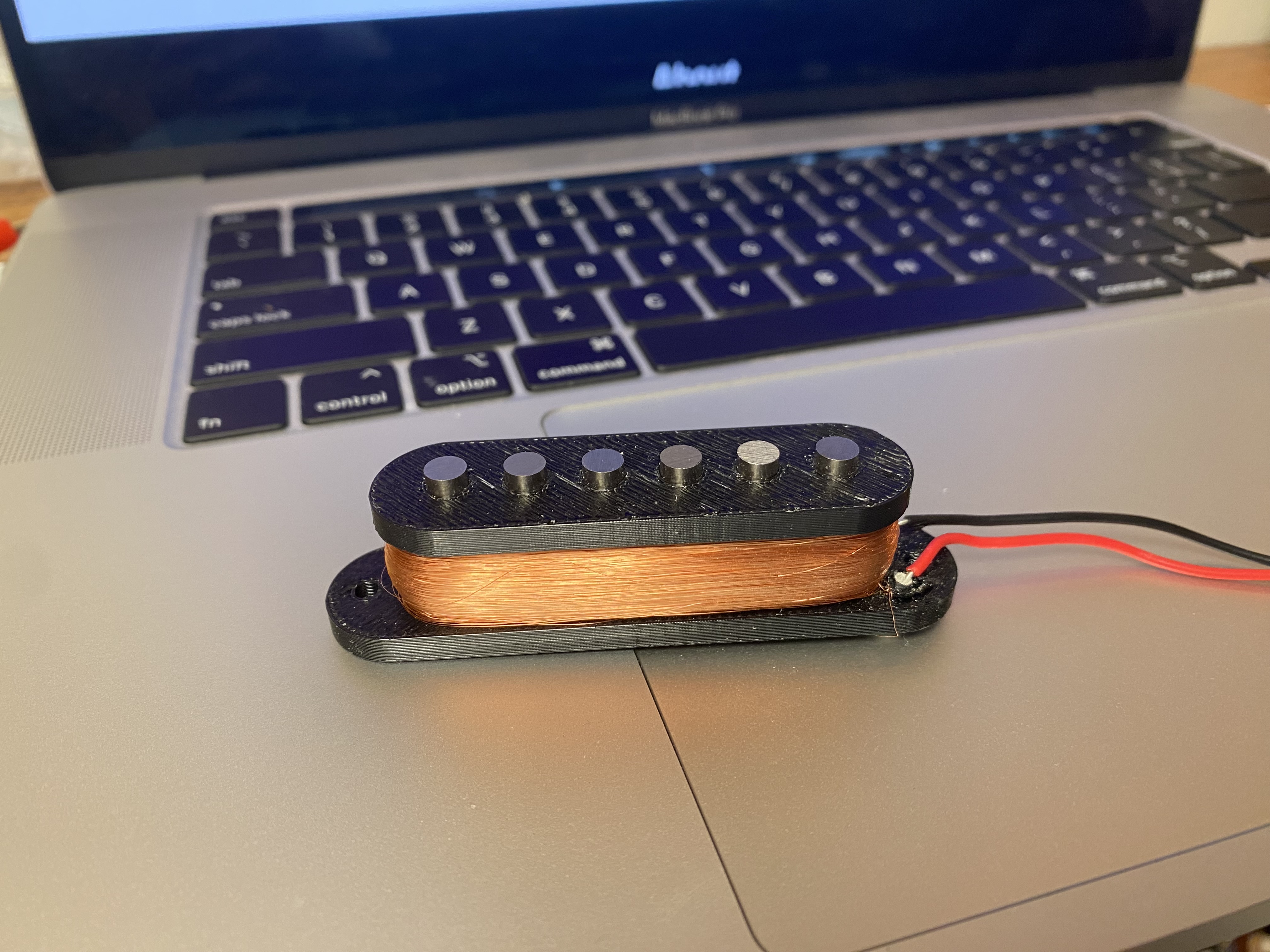
This week, our assignment was to "write an application that interfaces a user with an input &/or output device that you made." The deadline for the final project is getting closer and closer, so I figure it's about time I started making some progress. For my final project I'm going to make an electric guitar and in order to do that I'm going to have to make my own pickups. Pickups are made of a bunch of magnets placed side by side with a lot of magnet wire wound around them (usually around 8000 turns). When you strum a string on an electric guitar, this creates a very small induced current via the pickup that you can then run through an amplifier and speaker to get that electric guitar sound.
So, first things first, I needed a design for my pickups. I bought some magnets off of Amazon and used the dimensions on the website to make a design on Fusion360. My first design felt bulky compared to the pickups I'd seen on other guitars online and I'd printed it on the Prusa which had left a lot of annoying tiny strands on the overhang where the wire was supposed to be coiled. The second time around, I made the pickups smaller and I used the Strata printer. The big advantage of the Strata was that it had dissolvable supports, so after letting the parts sit in the chemical soup overnight, I was able to get perfect pickups. The spacing for the magnets was just a little tight, so I used a vice to force them into the pickup one by one. So the pickups were ready to go, but I still needed a way to wind them, which is where this week comes in.
Winding the pickups by hand would be a pain, so I definitely needed some kind of motor to make this work. My first thought was a stepper motor, because I figured I could also use the steps to count the numnber of rotations of the motor. The only problem was that it would be relatively slow, and I didn't want to have to sit through however long it would take to make 8000 turns. Luckily, my classmate Yohan was making an electric bass for his final project, and had already made an awesome rotary encoder to wind pickups for input week, so I figured I could instead use a DC motor and focus on controlling it with a MOSFET and PWM from a microcontroller.
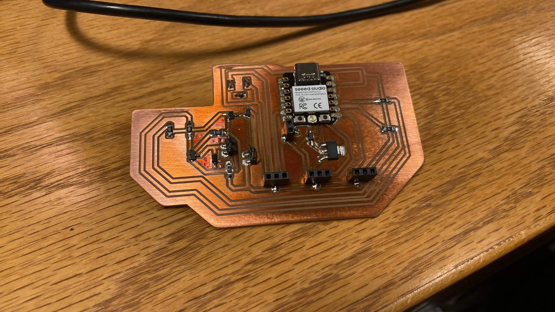
Using the XIAO C3 I threw together the schematic in KiCad with the components for another rotary encoder as a backup. Once the PCB design was done, I milled it out on the Othermill, soldered everything together using reflow, and hooked the board up to my laptop. My adjusting the PWM analog value (0 to 255) of the pin going to the MOSFET, I could adjust the speed of the DC motor by essentially opening and closing the gate to the MOSFET really fast. Once I flashed the program to the motor, I would need a way to control the speed of the motor without having to rewrite the code, so I did some searching and found that I could create a basic UI using the serial monitor within the Arduino IDE. There would be 4 basic commands: '-' to go a little slower, '--' to go a lot slower, '+' to go a little faster, and '++' to go a lot faster. Aaaaand, it worked! I included the code and video in embedded week, but here it is again:
                                                int motor = D0;
                                                const byte numChars = 32;
                                                char receivedChars[numChars];   // an array to store the received data

                                                boolean newData = false;
                                                int currSpeed = 0;

                                                volatile int num_edges = 0;

                                                void cb() {
                                                    num_edges += 1;
                                                }

                                                void setup() {
                                                    Serial.begin(9600);

                                                    pinMode(motor, OUTPUT);
                                                    pinMode(D1, INPUT_PULLUP);
                                                    attachInterrupt(digitalPinToInterrupt(D1), cb, RISING);

                                                }

                                                void loop() {
                                                    // Serial.println(num_edges / 2);
                                                    // Serial.println(analogRead(D1));

                                                    recvWithEndMarker();
                                                    showNewData();
                                                }

                                                void recvWithEndMarker() {
                                                    static byte ndx = 0;
                                                    char endMarker = '\n';
                                                    char rc;

                                                    while (Serial.available() > 0 && newData == false) {
                                                        rc = Serial.read();

                                                        if (rc != endMarker) {
                                                            receivedChars[ndx] = rc;
                                                            ndx++;
                                                            if (ndx >= numChars) {
                                                                ndx = numChars - 1;
                                                            }
                                                        }
                                                        else {
                                                            receivedChars[ndx] = '\0'; // terminate the string
                                                            ndx = 0;
                                                            newData = true;
                                                        }
                                                    }
                                                }

                                                void showNewData() {
                                                    if (newData == true) {
                                                        Serial.print("This just in ... ");
                                                        Serial.println(receivedChars);
                                                        if (strcmp(receivedChars, "+")) {
                                                        if (currSpeed > 0){
                                                            currSpeed = currSpeed - 1;
                                                            analogWrite(motor, currSpeed);
                                                        }
                                                        }
                                                        if (strcmp(receivedChars, "++")) {
                                                        if (currSpeed > 4) {
                                                            currSpeed = currSpeed - 5;
                                                            analogWrite(motor, currSpeed);
                                                        }
                                                        }
                                                        if (strcmp(receivedChars, "--")) {
                                                        if (currSpeed < 251) {
                                                            currSpeed = currSpeed + 5;
                                                            analogWrite(motor, currSpeed);
                                                        }
                                                        }
                                                        if (strcmp(receivedChars, "-")) {
                                                        if (currSpeed < 255) {
                                                            currSpeed = currSpeed + 1;
                                                            analogWrite(motor, currSpeed);
                                                        }
                                                        }
                                                        Serial.println(currSpeed);
                                                        newData = false;
                                                    }
                                                }
Lastly, if you want to make your own pickup machine, here's my pickup design and here's my KiCad board design.
It's Machine-building week! After a few days of brainstorming, the EECS section settled on what would be known as the Gershenforcer: a nerf-dart launcher that could launch darts at students who showed up late to class. Our design used these servos to control pitch and yaw of the gun to aim at the target. My job was to design a PCB to control the motors from a single microcontroller, and to solder all the components together. The schematic was relatively straightfoward: for each servo, I needed to have a connection to ground, to a 6-volt power supply, and to a pin on the microcontroller. The 6-volts would be provided by an external power supply via a through-hole barrel jack component. With the design done, I used reflow to solder everything together, and it was on to troubleshooting. We had a few issues with some unexpected shorts in the PCB, which luckily were not serious so we managed to fix them with an X-ACTO knife and some (slightly janky) soldering:

And here's a video of the Gershenforcer at work:
For more info on the group project visit this link, and to access the PCB design, visit this link.
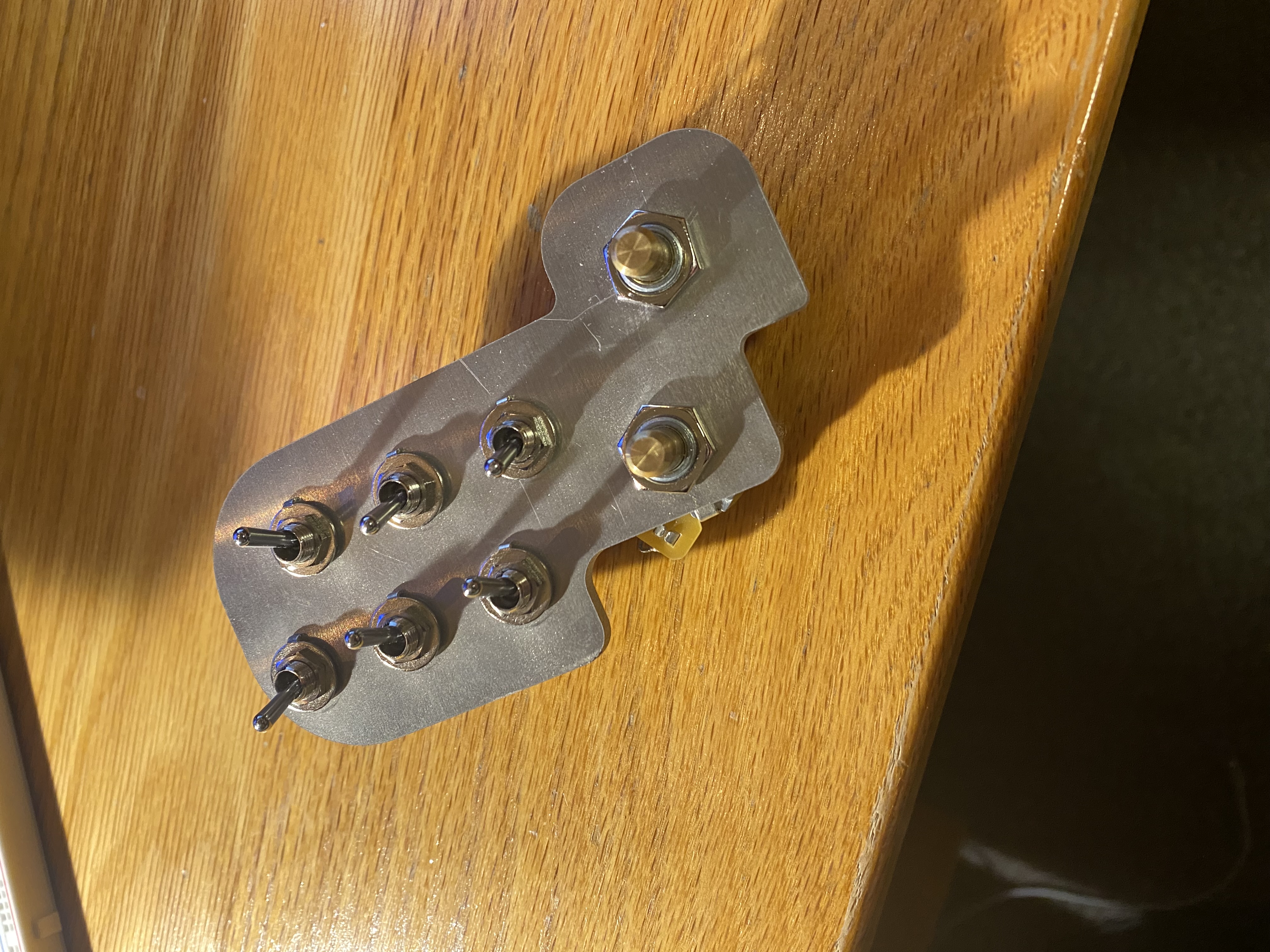
Wildcard week! A lot of exciting things but finals are just on the horizon and I need to keep making progress on the final project. My guitar design is done and I was able to get an aluminum sheet to hold the electronics on my guitar. My original plan was to just run it through the bandsaw, but when I saw that I could learn to use a waterjet, I figured that would be the perfect use of this week's assignment.
First things first, I generated a DXF file of the sketch of my part from Fusion360, which would be used to generate the toolpaths for the waterjet. I sent that over to Shah from the architecture shop and he showed me how to setup the waterjet. The main thing to remember is that waterjet uses an abrasive to cut through material, and it had a hopper with said abrasive that had to be refilled between jobs. Once that was done, we put down some bricks to hold the aluminum sheet down, adjusted the water level to cover the part and we were good to go:
And it fit the electronics perfectly!

For my final project, I made an electric guitar:
I had a few other project ideas before this, most notably a hydroponic garden and a modern walkman (whatever that means), but I wanted something that would be practical--something I might actually keep using once the class was over. I've always wanted to play an electric guitar, so I figured that these last three weeks before finals would be the perfect time to make this a dream come true.
There are a lot of different electric guitar designs out there, but I wanted something that would be relatively simple to CAD. And after some digging online, it seemed like the Fender Stratocaster, with its flat body and bolt-on neck would be a good choice. The dimensions of the Stratocaster are also freely available online, so it was an even better choice because of that. I wanted to do something special with the electronics though, and as I was looking into guitar designs I stumbled on the Red Special, a guitar designed and built by the lead guitarist of Queen, Brian May and his father. So what I envisioned was some kind of combination between a Stratocaster and the Red Special:

With a design in mind, it was onto making it a reality in Fusion360. I created an SVG file to get the shape of the Stratocaster, and I worked around my pickup design from Week 10 to get the sizing just about right. From there, it was a matter of making space for the electronics and the neck. I also made the electronics holder that I would cut during Wildcard Week--making sure to import the CAD files from the Digikey website to make sure that everything would fit well into the design. For the neck and fretboard, I looked online and was able to get the files for a standard Stratocaster from this Youtuber.
So the design was done, and now I needed some wood to run through the CNC. I searched through Youtube again, and I found this helpful video that explained the different kinds of woods that could be used for the different parts of a guitar, and the dimensions that they had to be. Not wanting to make more than one trip to get the wood, I saw that I could make the entire guitar out of maple, and I found that there was a lumber shop that was about a 30 minute bike ride from my dorm. Once I got the wood, I had another problem; namely, the guitar body was so big that I'd had to buy four separate blocks of wood that combined would be enough for the body. I didn't know a thing about gluing wood together, so reached out to Chris from the architecture shop and he taught me how to run the wood through a planar to get all the edges nice and straight, and then I left the pieces gluing overnight:
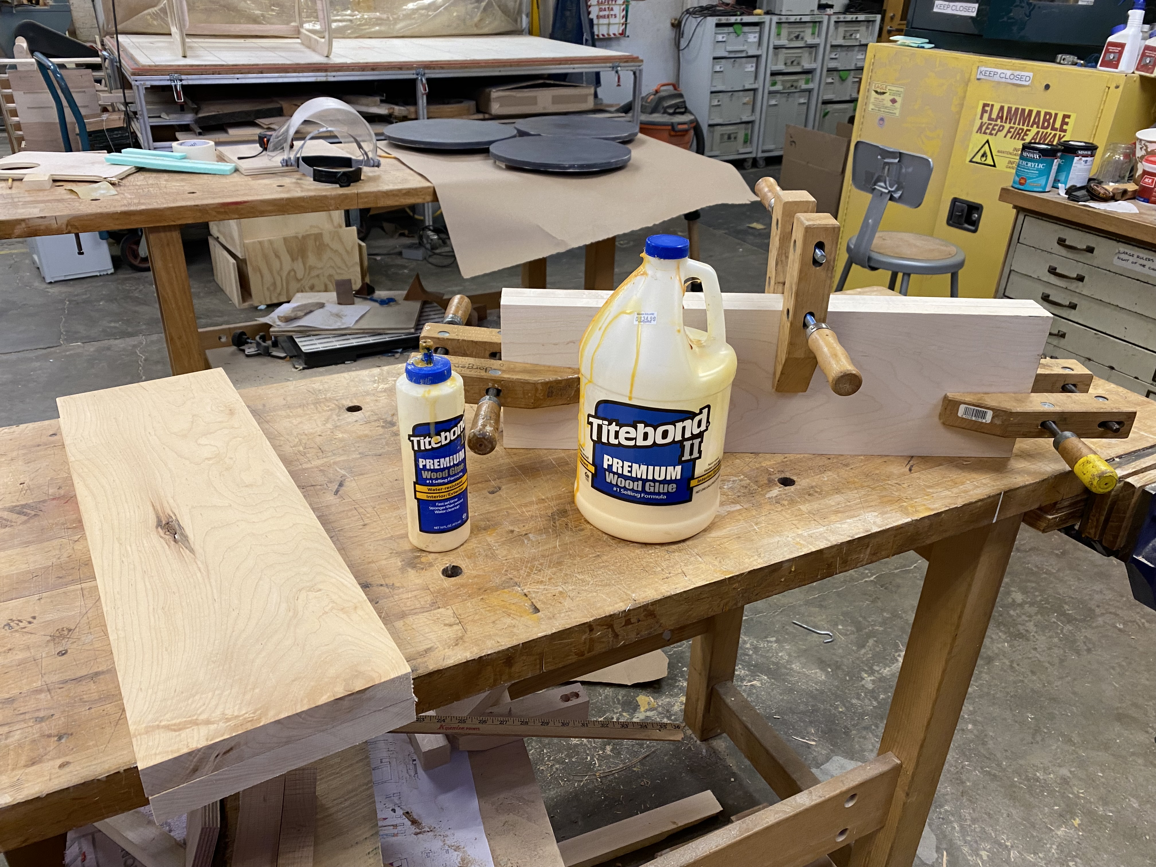
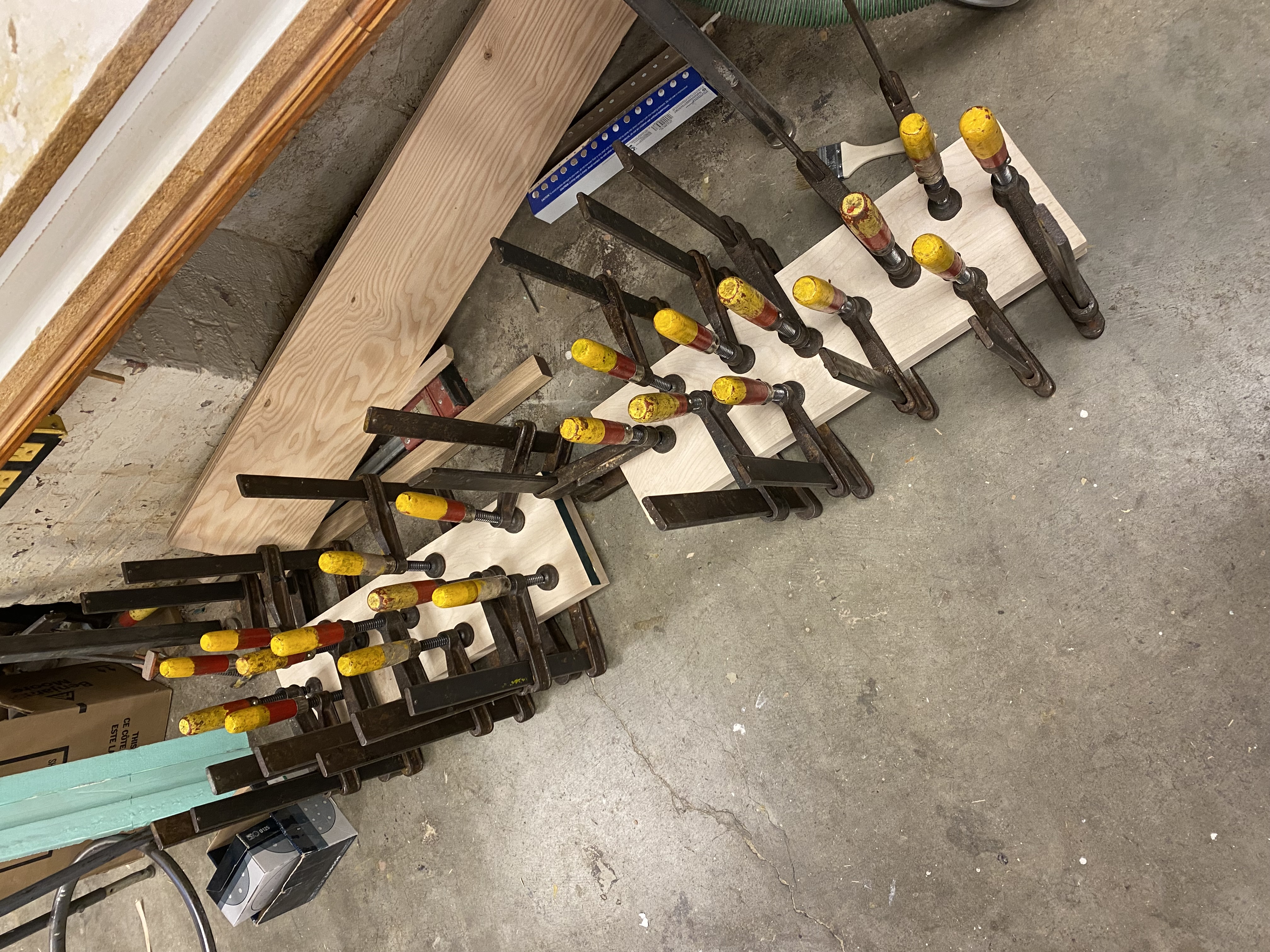
The wood was ready so it was time for CAM! With a lot of help from Anthony, I was able to finish up the toolpaths for the body and neck, and pretty soon my block of wood was looking like a guitar!
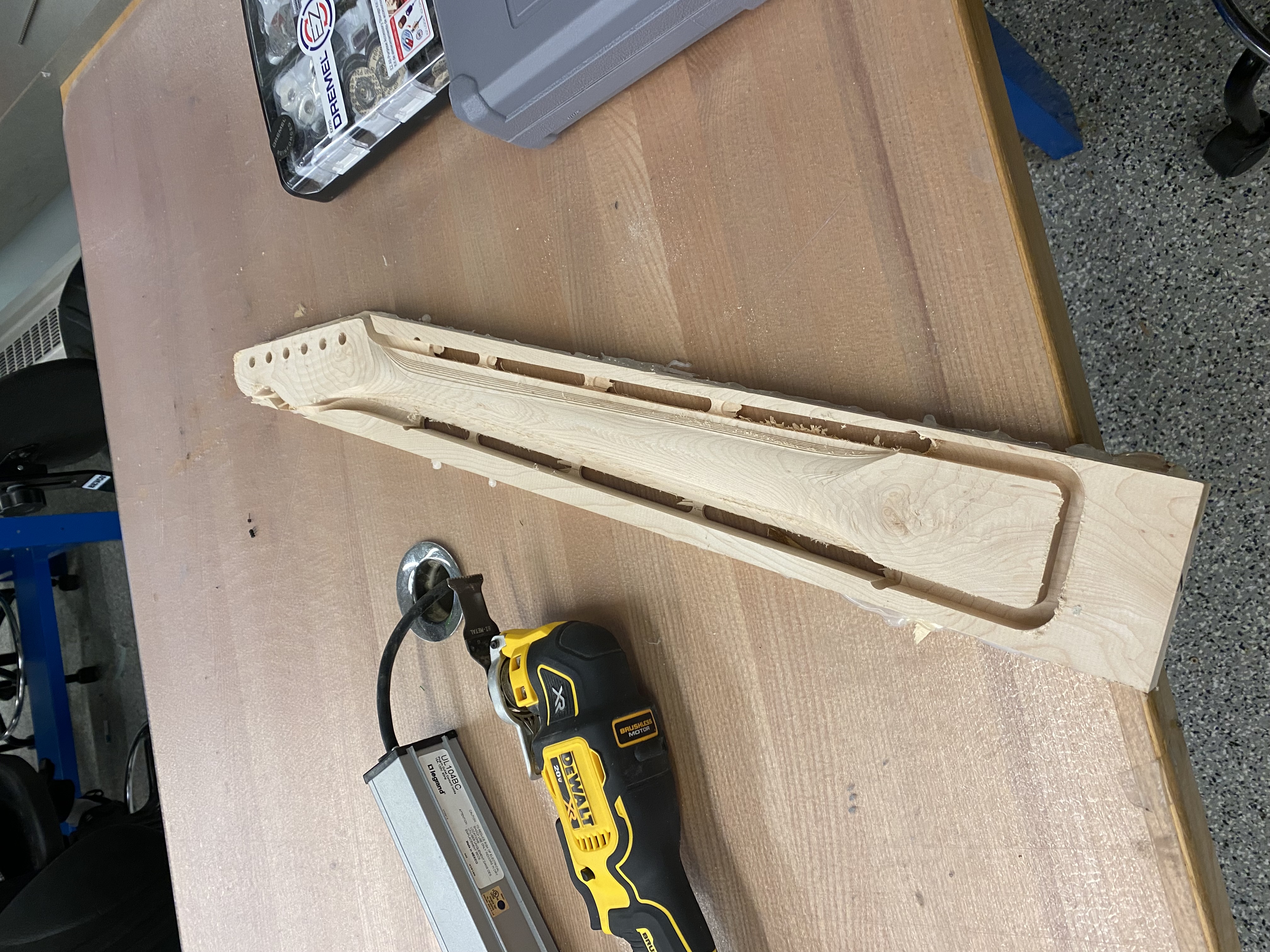
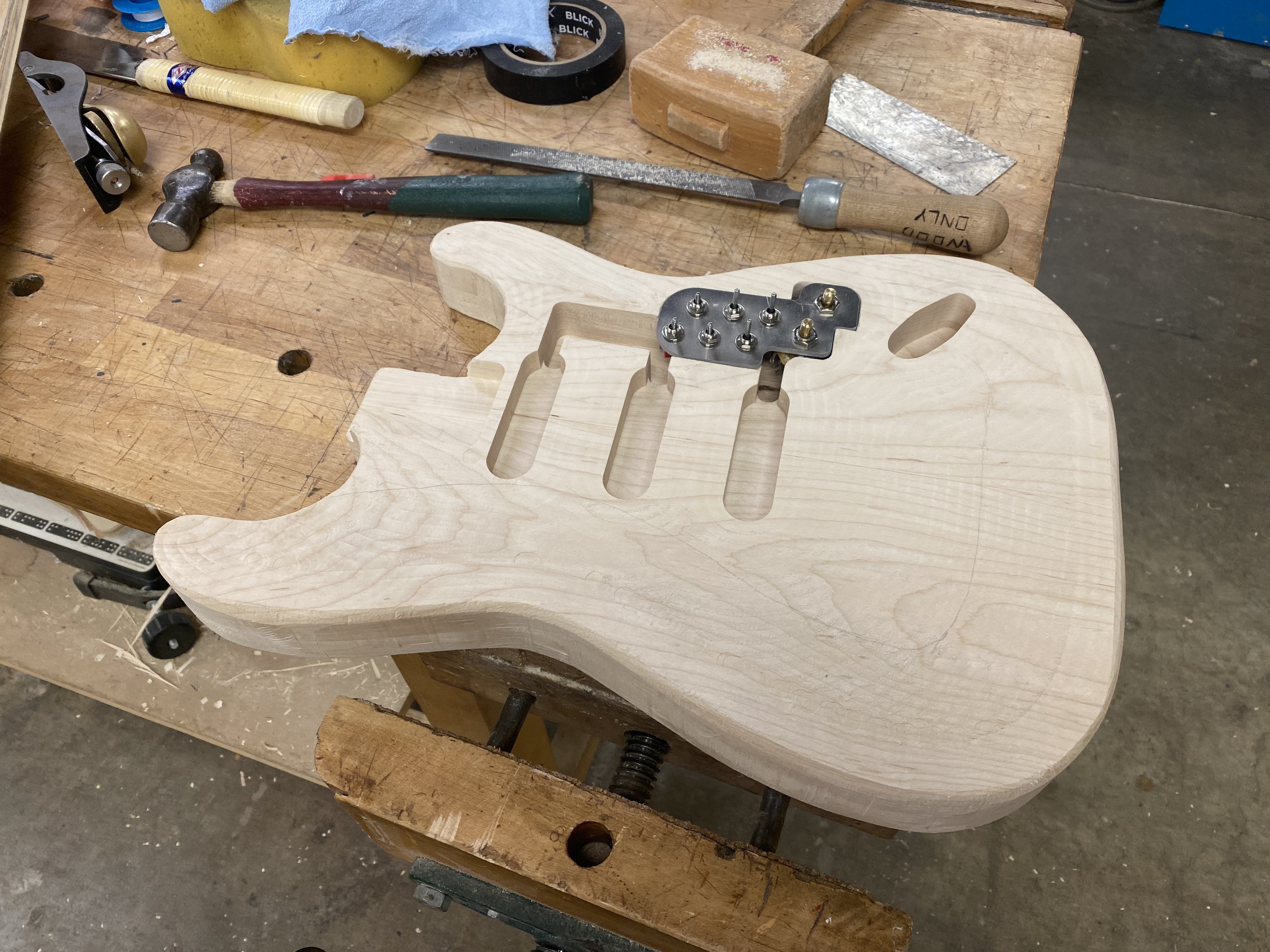
My biggest regret about this project was not fully taking advantage of the CNC, however. I decided to only CNC one side of the guitar neck and to do the fretboard by hand, which ultimately ended up costing me hours and hours of wasted time over the next couple of days. But, in the end the CNC came to the rescue and I was able to get a perfect fretboard for the guitar.
With the body done, it was just a matter of putting everything together. With Yohan's rotary encoder working and my motor control PCB done from Week 10, I started winding the pickups for the guitar:
This turned out to be harder than I expected, and it took several nights of failed attempts to get the three pickups I needed for the guitar. For one, the pickups were using 42 AWG wire, which I quickly found out could be easily broken by the motor if I wasn't careful. If the pickup was wound correctly, there was also the challenge of soldering wires to the thin wire without melting the 3D printed structure that supported it, which I also had to learn the hard way.
With the pickups done, I was onto the home stretch. I bought a truss rod, which goes right under the fretboard to support the neck from the tension in the strings, so I glued them together and again left it overnight with clamps:
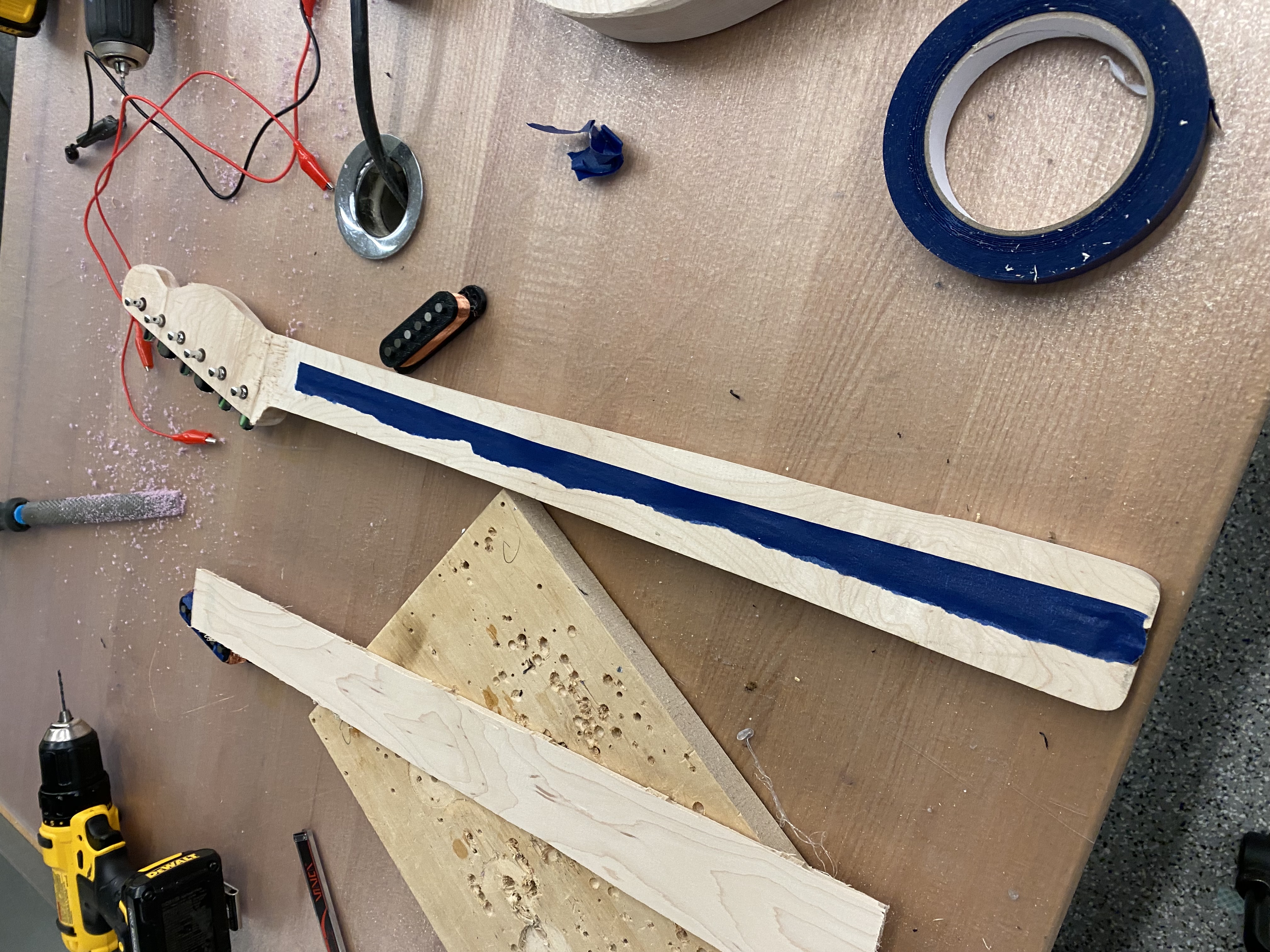
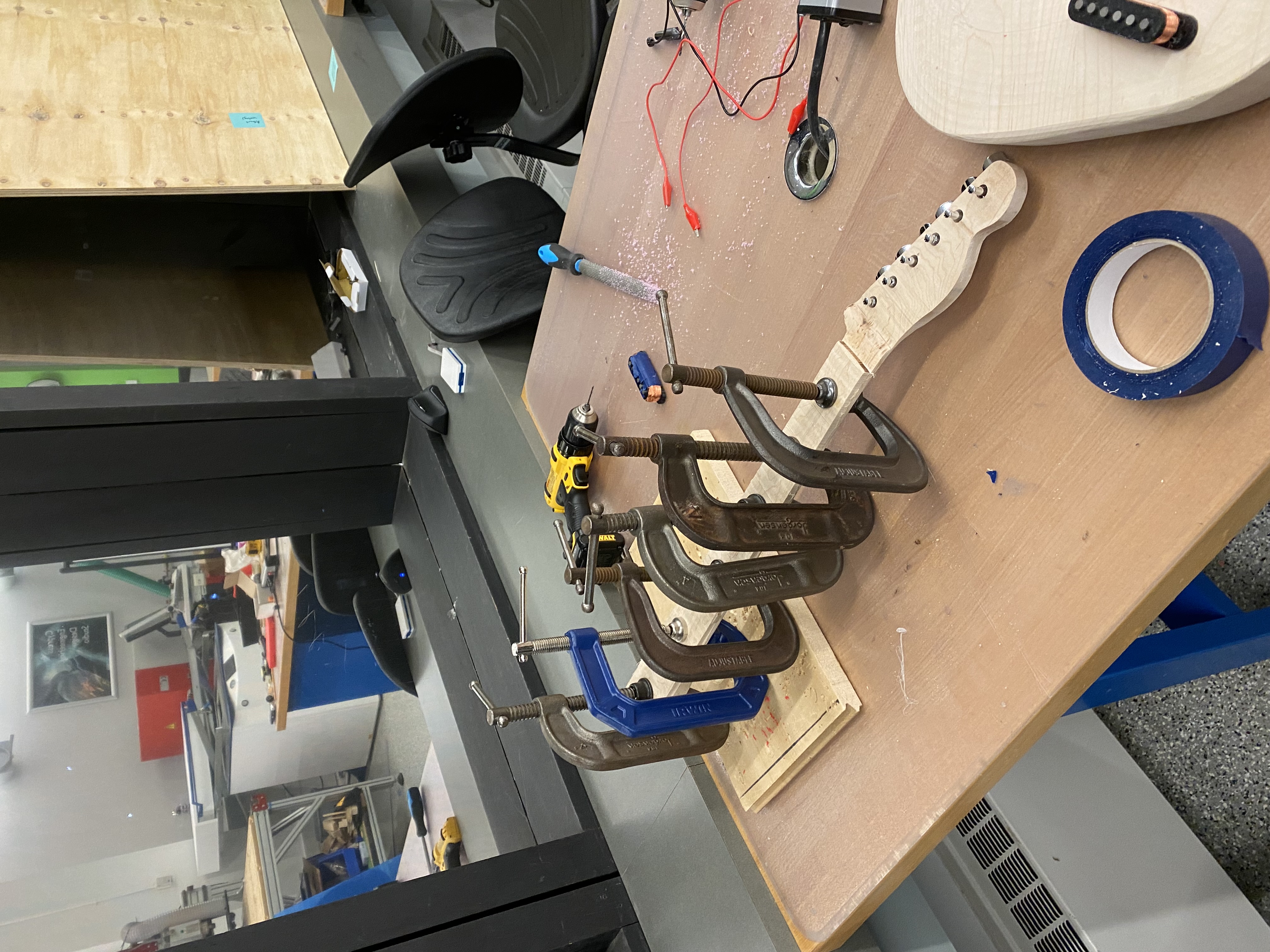
In the morning, the neck was ready for the frets, so I cleaned out the holes with a hacksaw and superglued them into place. Then I bolted the neck onto the guitar, attached the bridge and the tuning pegs, and tightened up a string for a sound test on Yohan's amp:
It wooooooorked! After all those hours of working on the guitar, I couldn't be more happy that I could finally get some sleep before the final presentation the next day. Now well-rested, I made this one minute demo video showing the guitar working on my amp:
And an attempt to play Little Black Submarines by the Black Keys:
So finally, to recap: