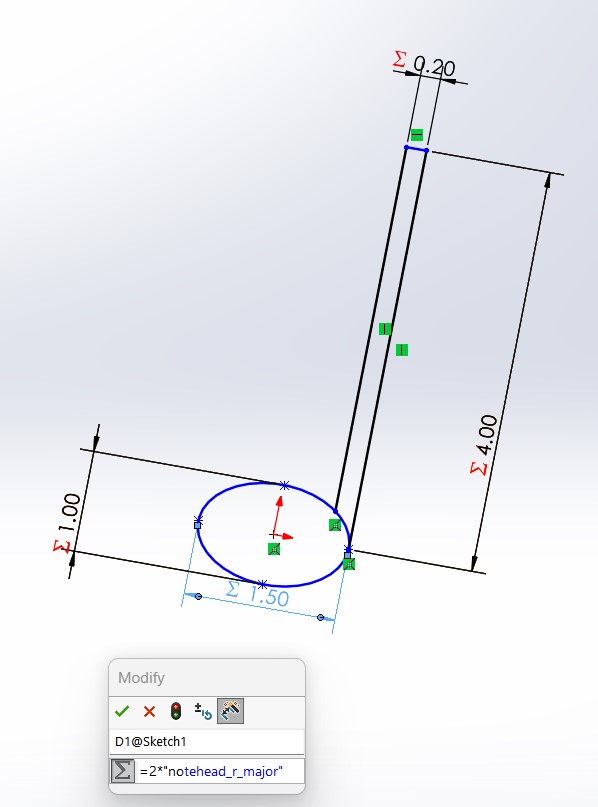
Sticking with the musical theme this week, I wanted to make a parametrically designed set of music notes that could slot into a musical staff made of cardboard. I jumped right into Solidworks to create a base music note from which I would get the parameters to design other types of notes and the staff to hold them:
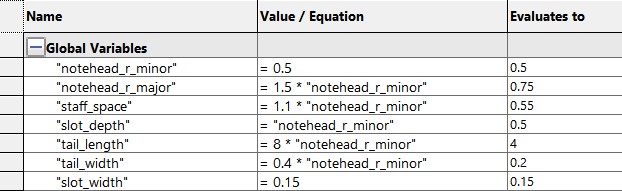
I verified that they were robustly parametrically designed and that changing the base parameter (the minor radius of the ellipse forming the notehead) would correctly change all other parameters:
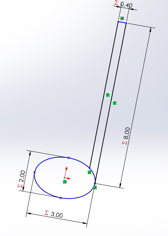
Then, I worked on creating a slot for slot-fitting with proper dimensions based on the thickness of the cardboard (not yet accounting for the laser cutter kerf, I just wanted it to be part of my initial design):
After this step, I actually decided to pivot as I didn't think that this was the best medium for creating something with music notes. The stems would be very thin and there would be few ways to connect the pieces together. So, I set out to create a more general construction kit of laser-cut shapes. I decided to make square, rectangle, triangle, hexagon, and 90 degree arc pieces, and set up my equations as follows:
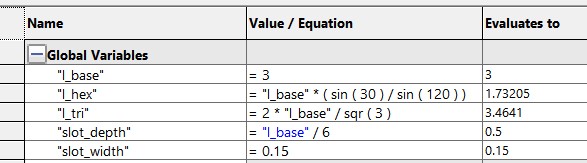
As shown in the equations tab, l_base, which is the distance from the base to the top of all of the shapes, is 3 inches. The l_hex and l_tri variables are the side lengths of the hexagon and triangle, based on l_base. The parameters of the rectangle and arc are directly based on l_base and thus don't need their own variables. Here are the sketches laid out together:
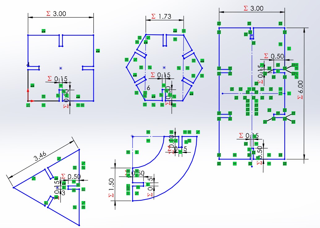
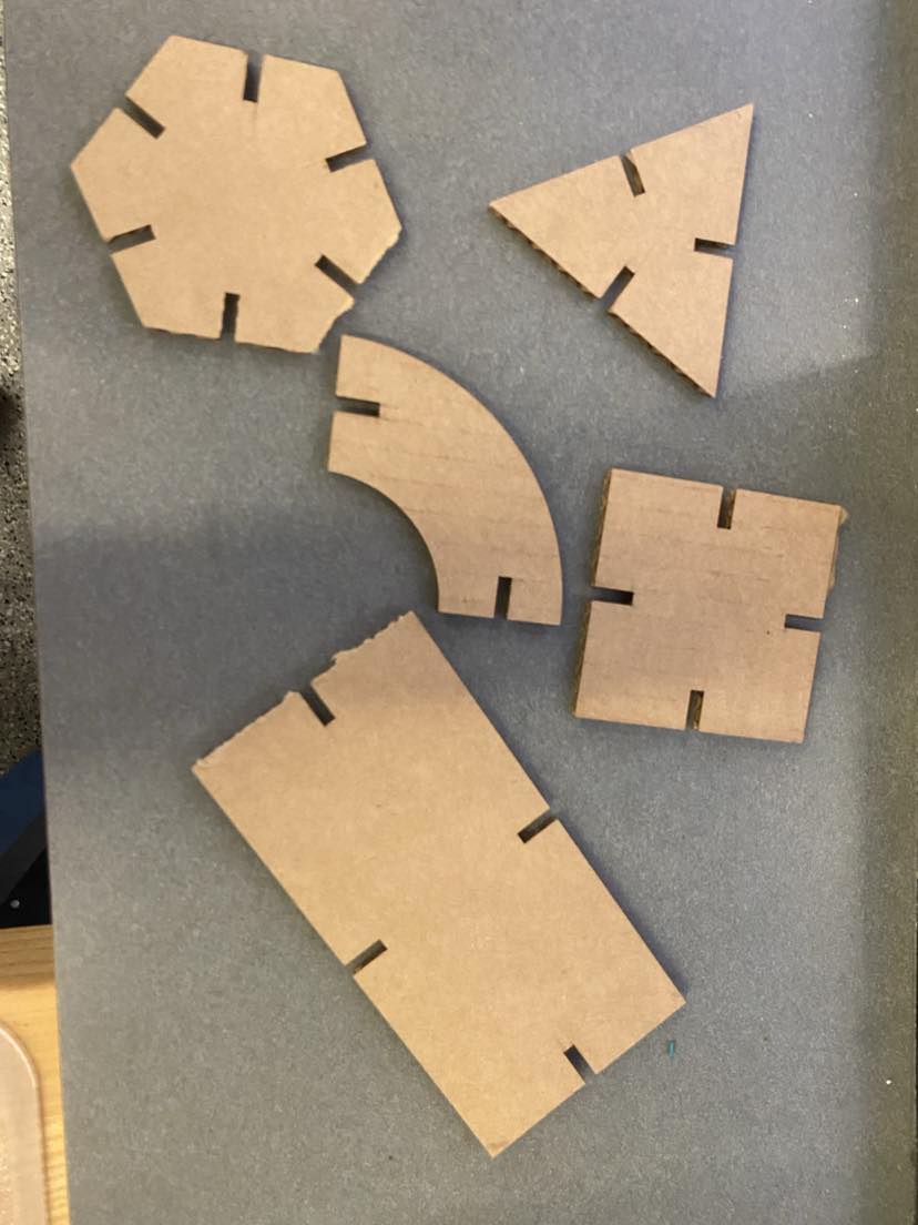
Note the number of relations to ensure that they are fully parametric, and thus changing the value of l_base to anything will maintain all relative shapes and sizes. Note in particular the additional construction lines on the hexagon, which did not maintain its shape when resized before I added them. I converted the sketch to a DXF file and used the shapes from the file to make a test print, which turned out great:
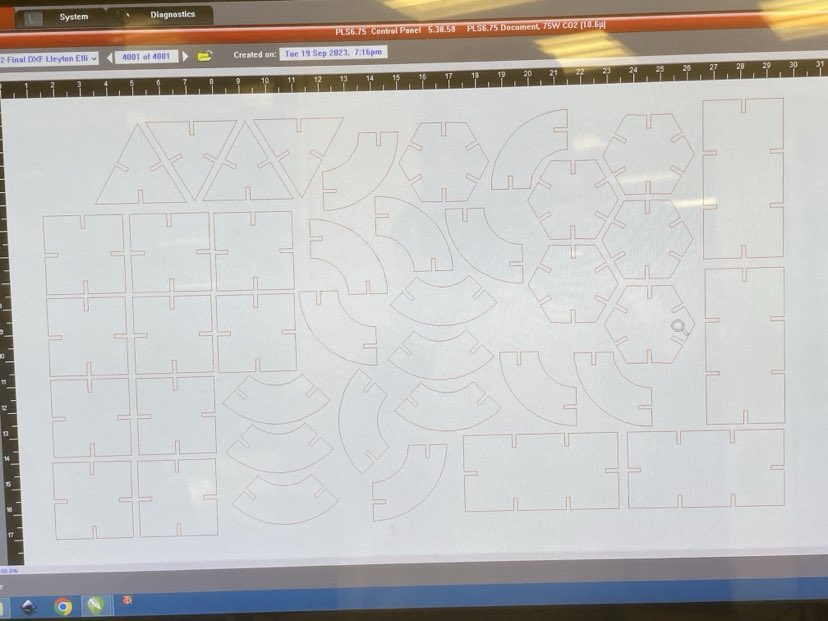
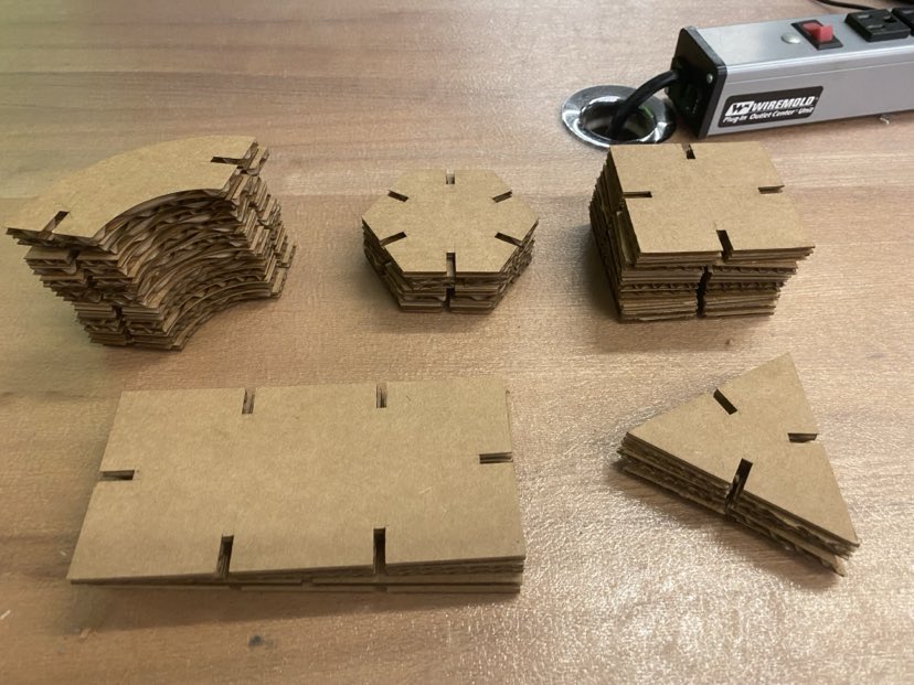
With the test cut having worked very well, I laid out as many shapes as I possibly could on the canvas and started the big job on the laser cutter:
I ended up with these stacks of shapes. I did notice that the ones near the edges were slightly more difficult to remove from the cardboard; this leads me to believe that I should've set the power of the laser cutter a little bit higher, as not all of the cardboard is at the same level as the middle which was slightly bowed. Either way, they turned out ok.
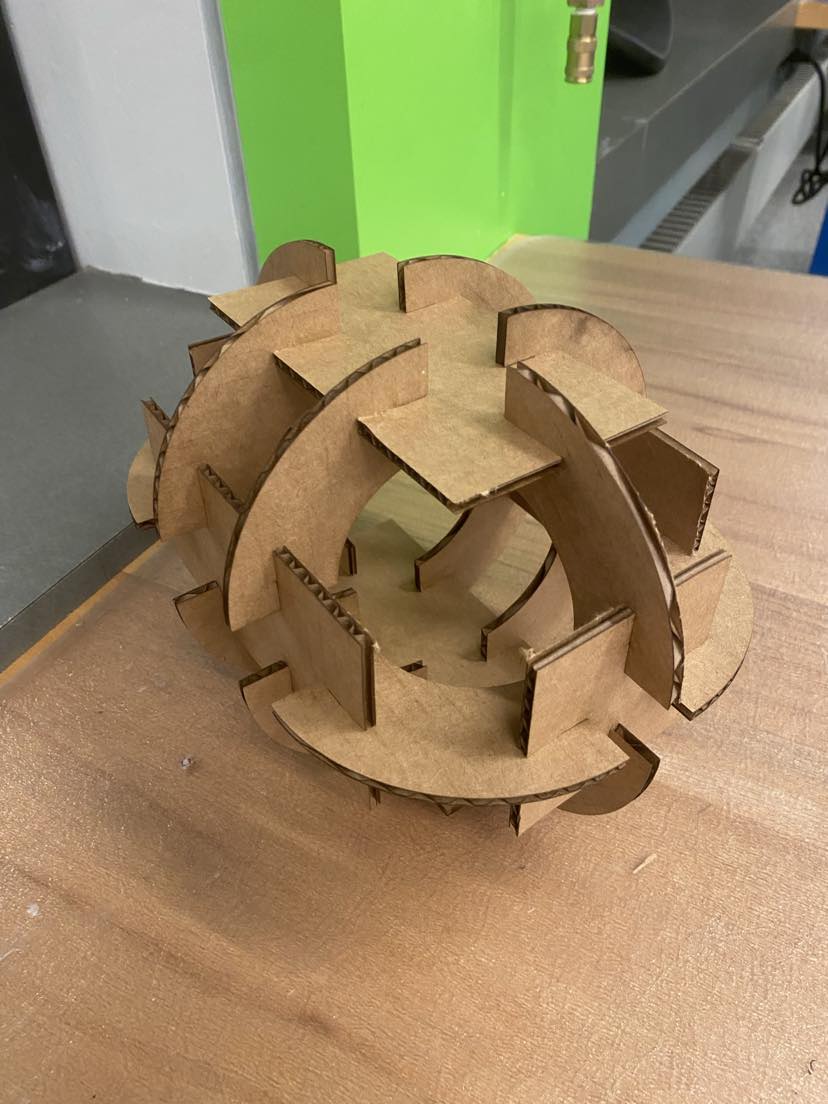
I made an example build using my shapes and they fit together very well!
Design Files
CAD with Sketches of Shapes: shapes.SLDPRT
DXF with Final Shapes: week2_final.DXF
Thoughts, Lessons, and Takeaways:
I have used a laser cutter before, but getting better at parametric design is definitely something I haven't put too much thought towards and was thus nice to reinforce. It's satisfying to have CAD files that are easily changed based on design constraints and parameters and I'm sure robust/parametric design will save me lots of time in the future...