Week 3 Assignment: Write a Program for a Microcontroller Development Board to Interact and Communicate
I've changed my website format, and all subsequent pages will take this form. I've also changed my final project and this is the week where I first begin to build the foundation.
In short, I browsed through old projects and looked at several of the products Neil had shown us in class, and realized that the best and most notable ones were the projects where the students clearly had fun making them. So, I landed on what I believe to be a fun and unique idea: an arm that will shake your hand and then tell you how good your handshake was. The following page demonstrates my process for building up the basic logic of what will eventually be a component of my final project.
I began by setting up my board. I decided to use the Raspberry Pi Pico W board with an RP2040 chip on it. Somebody had recommended that I use MicroPython to interface with the board, but I'm much more comfortable with C++ and the Arduino IDE so I decided to use that instead. The setup was relatively simple: navigate to Tools - Board - Boards Manager and search for the Raspberry Pi Pico/RP2040 package. After installing, selecting the appropriate board from the dropdown in Tools - Board would automatically set up the IDE to upload to the RP2040 via UF2. I tested it with the Blink example sketch and ran into a small issue of the upload sometimes failing with odd error messages, but Anthony told me to set the CPU speed to 225 MHz (Overclock) in the Tools dropdown and that fixed the issue.
Next, I got to work wiring up my circuit on a breadboard. My circuit was quite simple: a potentiometer as an input with two LEDs as an output. I wanted the green LED to be on when the potentiometer was within a certain range of values, and the red LED to be on in all other cases. This mirrored the logic of my final project (where a "good" handshake corresponds to a hand squeezing force that isn't too hard or too light).
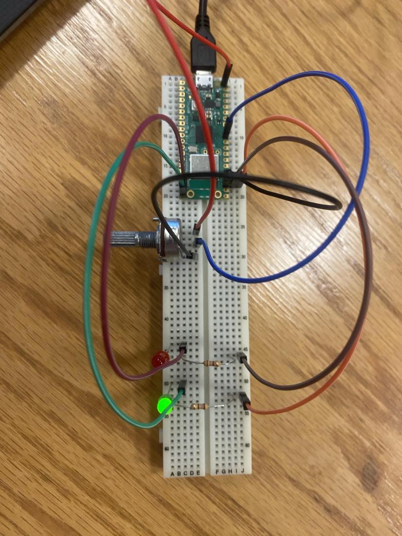
For some reason, I only have a picture of this step from before I added header pins to the Pico W (I'm writing this a little bit later; don't ask me why I didn't solder from the get-go, I don't have a good answer). Either way, I quickly got to soldering and then remade my breadboard setup with that finished, then got to coding. I used some conditionals to drive the logic of my system, with a delay of 100ms in between each one (the delay was somewhat arbitary, I figure it should be 10-20ms or higher but the actual value doesn't matter too much). Note that only pins 0-3 of the RP2040 are analog capable, so I needed to have the potentiometer connected to one of them (it's on 0 in my setup).
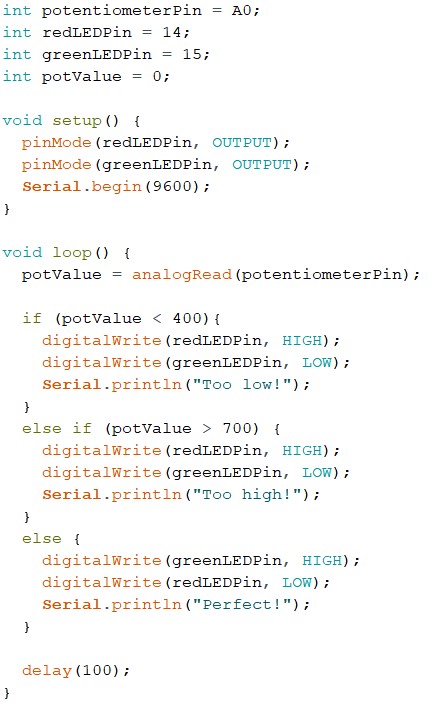
As you can see, I also had my code print a string corresponding to the position of the potentiometer to the serial line. I'll want my final project to communicate my data somehow, probably using serial, so this is a decent reminder if nothing else to send the data that way eventually. Here is a demonstration of my working setup!