Final Project: Handshake Robot
Welcome to my final project page! This is a work in progress, and will be until I'm completely finished with my project, but from this point (about Week 9, input devices) onward, this will serve as a comprehensive guide to my final project. It's broken up into 3 parts: concept, where I describe and model my project, journal, where I write thoughts about the final project as I do the weekly projects, and implementation, where I document the process of making this project!
Concept
My original final project idea was a multi-modal desk that could switch from a working mode to a music production mode with the push of a button. I still really like this idea and might try something similar on my own time, but in looking back at old final projects I found that the best ones and/or the ones that stuck out the most were those which people really seemed to have fun with. With this as a guide, I pondered and eventually landed on my project concept: a robot that shakes your hand and tells you how good of a handshake you have.
As a Control, Instrumentation, and Robotics concentrator within Course 2-A, I feel this will allow me to stay relatively within my comfort zone while still challenging myself as I've never designed a robotic system completely from scratch. Also, getting to play with (and potentially fabricate) sensors and output devices is appealing as someone without substantial electronics experience entering this semester. It's also simply fun and lighthearted, and I'll enjoy testing it on my friends.
As always, I will include the design files, alongside my thoughts, lessons, and takeaways, at the end of the page. I'll also take care to answer each of Neil's big final project questions.
Journal
Week 9: I've definitely thought about this project in other weeks but this is the first time I'm putting in the time to record my thoughts, especially regarding how the weekly assignments can contribute to my final project effort. I'm breaking this down by large-scale tasks which I believe can be approached separately. Technically this isn't true but this helps me organize my thoughts.
The tasks are as follows:
- I need to design and fabricate a simple (probably two-axis) robotic arm and decide how to actuate the joints (will there be a motor on the second joint or will I have some sort of belt-driven setup where both motors are at the base?).
- I need to calculate the dynamics of the arm and figure out how to control it: constant-setpoint with a slow control system? What best mimics a real handshake? I anticipate this being trial-and-error, and it's also only possible once my arm is at least designed, if not fabricated.
- I need to design a sensing apparatus that feels at least somewhat like a real hand and houses a PCB and any electrical components of the sensors I include.
- I need to successfully define and implement the logic of my system: how much force is too much? What makes a "good" handshake? Included in this task is my output; how do I express whether the handshake was good or not to the user?
I am further along some of these tasks than others but I think I'm in a decent place with all of them. Many parts of this will simply take time so I definitely shouldn't procrastinate and should prepare for some potentially long hours as the due date for this project draws near. I'm far more excited than apprehensive, though!
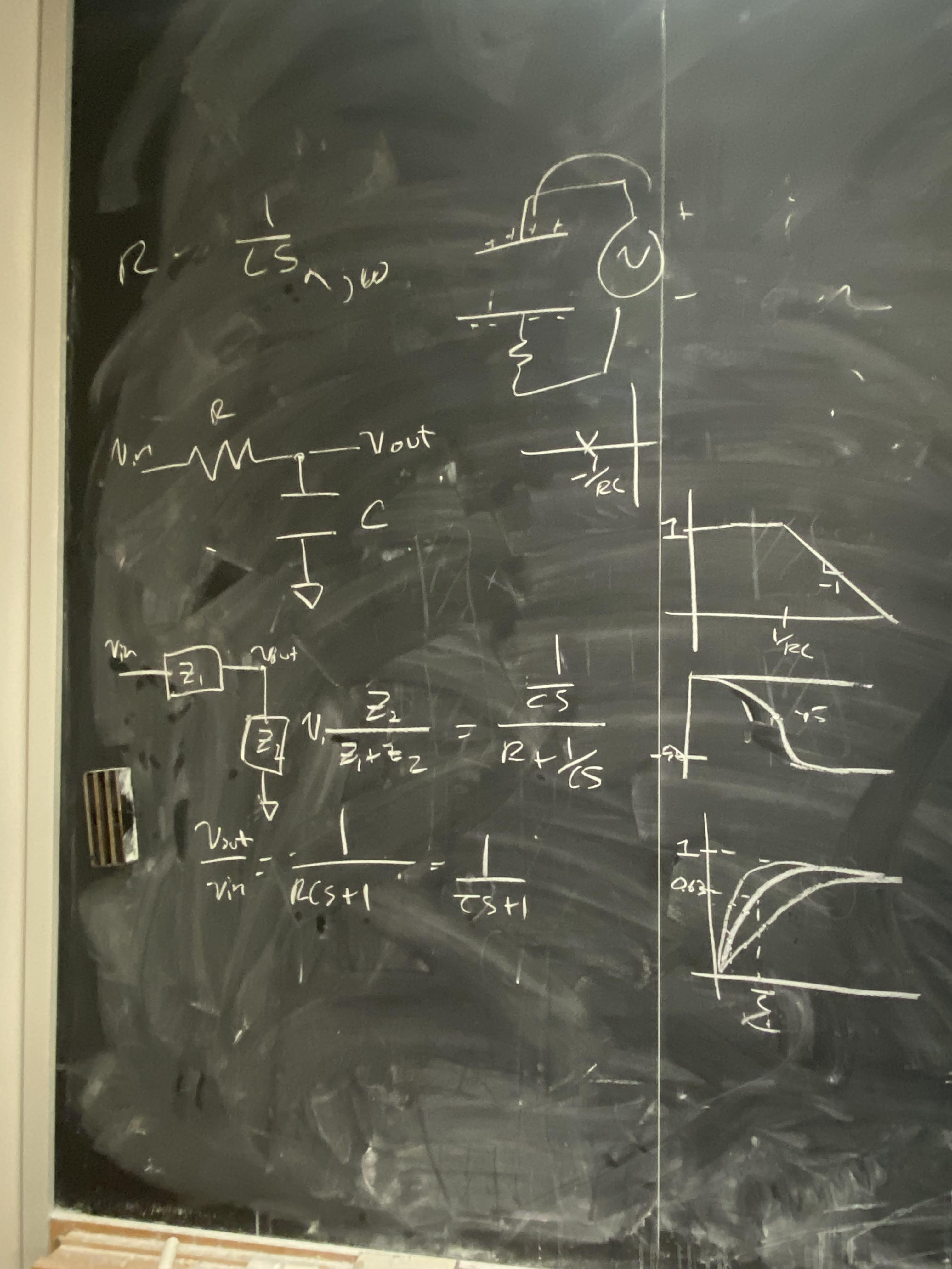
Week 10: I shared my project idea with one of the grad students who is on the 2.004 course staff with me, someone to whom I look up to quite a bit. We discussed the advantages and disadvantages of the sensor I used for Weeks 9 and 10, and also discussed alternative sensing possibilites. We discussed how I could fairly easily design a PCB that basically puts the capacitive force sensor into a voltage divider. Though the time-domain behavior of a voltage divider with a capacitor gets a little complex, he reframed my thinking by showing how easy it is to make a transfer function taking V_in to V_out in this system by looking at the components in terms of their impedance in the frequency domain. As shown in the image below, this system is basically just a low pass filter (seeing the derivation of the time constant for an RC circuit was a fun bonus of this exercise), which I can very accurately predict the step response behavior of and can thus use as a pretty good sensor. If I can provide a consistent V_in and reliably measure V_out, this is pretty logically straightforward as I'd be able to figure out the capacitance almost exactly based on when the step response reaches (1 - 1/e).
He also gave me an Adafruit MPR121 12-touch-sensor-compatible breakout board, which I didn't realize was available to me via the 2.004 lab. There's lots of good documentation on setting up various types of sensors with this board and I'll definitely look into it, though the thought of doing it all myself is quite tempting. I think I'd like to stick to the "everything is made by me" but this could be a useful tool if I end up dissatisfied with any other sensing methods I attempt.
Week 11: I figured out my communication protocol for my final project! Read about it here. Please note that from this point forward, I may make references to things that are not directly on this page, but are in my weekly assignments pages, as I made sure to do many weekly assignments in a way that would contribute to my final project. All of the design files will be included here, though.
Week 12: I figured out an interface for my final project! Read about it here.
Week 13: Machine Week. Bigger fish to fry, people dribbling into class late is a problem that must be fixed.
Week 14: Now that I'm printing hands, I've begun to really think about how to put this whole thing together. I started designing a wrist joint that will be finished by next week.
Implementation
It's time.
Given that much of the code base has been built up for this project come final project week, I had a very clear first goal: fabricate the darn thing. My first instinct was an actuated robot arm with waterjetted parts. Let me tell you why this is no longer a good idea a week out from the project's due date:
1: Metal is heavy, and I don't anticipate any motors I use being that strong
2: Actuation is a big design challenge that is somewhat superfluous to my actual project goal
3: I do not know how to waterjet
The third one was not due to my own negligence but an unfortunate set of circumstances; the person by whom I was supposed to be trained on the waterjet got sick. Regardless, I don't think that idea was the way to go anyway. As a member of the EECS section, I have access to up to five 3D printers, and a quick glance into the back room revealed that none of them were in use. Exciting. Just as I had begun designing my wrist joint to be 3D printed, I began designing everything else too.
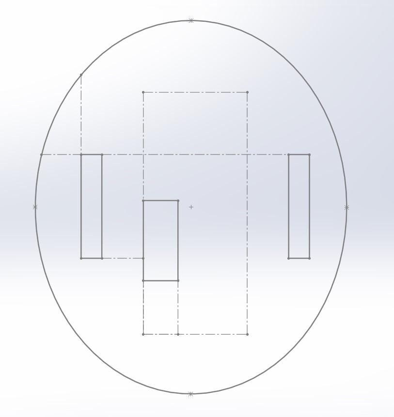
I'll begin by discussing the wrist joint. It was designed to fill the holes I designed into my hand model during Wildcard Week. The base of the hand was an ellipse of about 45mm by 54mm, so I sketched that out, as well as sketches for extrusions that would match the holding slots on the hands. Additionally, I added a small rectangle in the sketch for the USB-C connector to my Xiao RP2040 microcontroller, offset slightly to avoid collision with the rotational axis. The sketch looked like this:
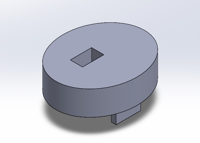
A few extrustions and cuts later, I had this:
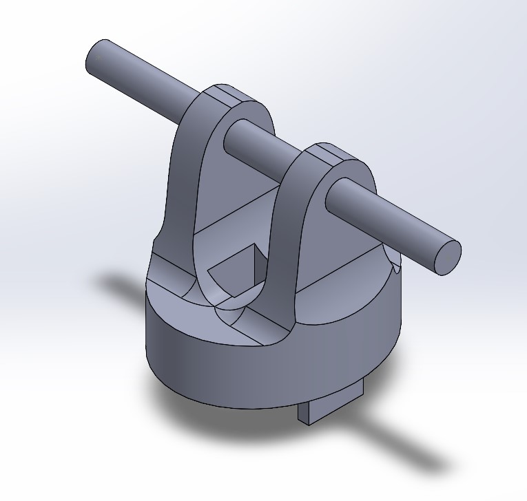
Next, I made a decision that would become standard across my entire design. I used 7.5mm diameter rods as axes to connect everything, starting with this wrist joint. Some simple extrusions, cuts, and fillets later and I had thsi:
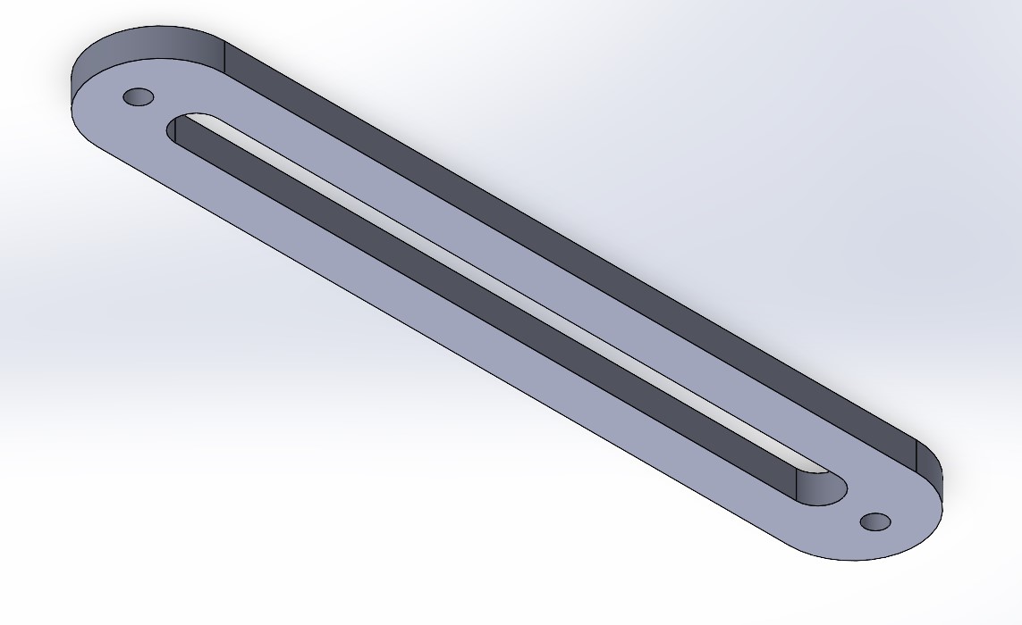
I chose to make the rods a little extra long in case I wanted to design a coupling of some sort to actuate them. The next step was to make an arm "bone", as it were. This one was very simple; I wanted it to be somewhat hollow to keep it light, so I sketched two slots, one inside the other, and 7.6mm holes at either end (for the sake of engineering tolerance, an extra 0.1mm on the holes seemed to give me the freedom of motion I needed):
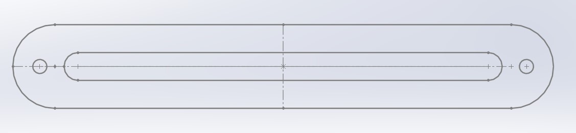
Extruding it gave me a beautiful looking piece to add to the assembly.
The last big piece to make was the base. I knew I'd have a rod connecting the two arm bones at one end, so the base also needed a hole. I also knew that the arm itself would be too heavy to realistically counterweight with just 3D printed materials, so I added two "legs" which I could tape down to whatever surface my project was sitting on. This was another relatively simple design, and I feel that getting into the minutiae of exactly how I designed it would be counterproductive to the flow of my final project story. The design file, alongside all of the other ones, is attached at the bottom of the page.
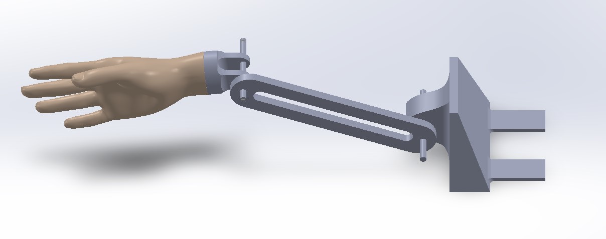
Before printing, I put all of these parts (plus a basic rod) into an assembly to see how they'd fit together. The only difference between the assembly and the real system is that there are two arm bones in the real thing, but they're identical and most of the system is symmetrical so verifying one verified the other.
I began printing all of the parts in parallel (I was lucky that four 3D printers were open). In the meantime, I had another task: create my final PCB and the sensor to go along with it. This PCB design was VERY simple; the PCB I used for the weeks of input and output devices uses the exact same sensor scheme. I did, in fact, decide to go with capacitive sensing based on Robert Hart's tutorial, as I mentioned in earlier weeks. All that was needed for this was an input pin, an output pin, and two megaohm resistors branching out from the input pin, one going to ground and the other going to Vin. My schematic was thus super simple. I did, however, add a few breakout pins just in case I ended up wanting to use them for something else.
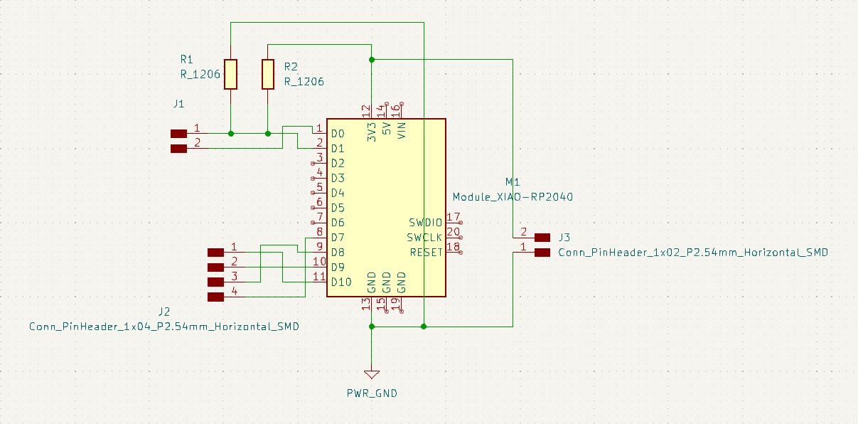
In terms of the PCB layout, there were a couple design considerations to take into account. Firstly, the PCB had to be 35mm wide, which wasn't much of an issue. Secondly, I had to make sure the USB-C port lined up with the hole I designed into the wrist joint, which took a little bit of effort but again really wasn't that bad. Everything else fell into place very naturally and the PCB layout ended up like the one shown below, and then I got to milling!
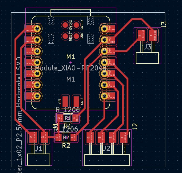
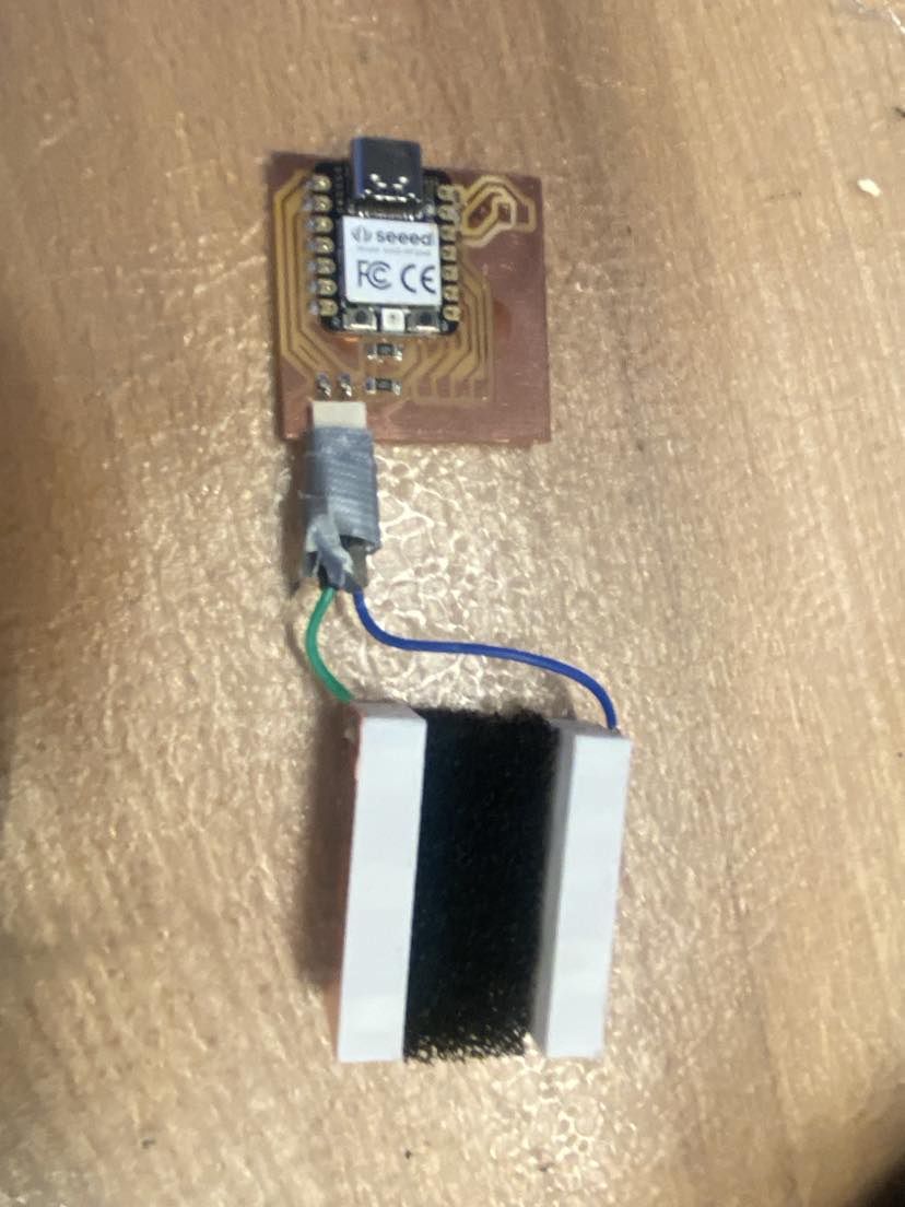
I milled my PCB, which only took about 15 minutes, and then got to soldering. As I mentioned in Week 11, I had explored reducing the size of my sensor's electrodes, which was now necessary to get them to fit in the hand. I 3D printed two small (35mm x 15mm x 7.5mm) rectangular prisms and applied copper tape to one side of each, then soldered jumper wires to them and plugged them into my board. This process was very similar to the one in Week 8, but the parts and process were more sophisticated and I knew what I was doing a little bit more. After some duct tape to make sure the jumpers stayed attached to my PCB, I had completed my sensor and merely needed to push it into my hand.
As long as my communication protocol and interface from weeks 12 and 13 worked as well with this new system, I was confident in my electronics for the project. After waiting for the prints to finish, it was time to begin putting it all together.
The initial fit of the hand, wrist joint, arm bones, and dowel was great! The wrist joint-arm bone connection was very tight at first and required a little bit of sanding so it could move a little bit, but I wanted my wrist joint to be pretty rotationally stiff so I'm glad it wasn't too loose. I was still waiting for the base to finish printing, so the next step was actuation - or was it? I had a bit of an epiphany when thinking about my actuation plan. I wanted to implement some kind of rudimentary, somewhat weak proportional control so that any movement the user made away from the setpoint was met with a gentle push in the other direction, to mimic the feeling of shaking a real person's hand.
Wait a minute, I just described the effects of a spring.
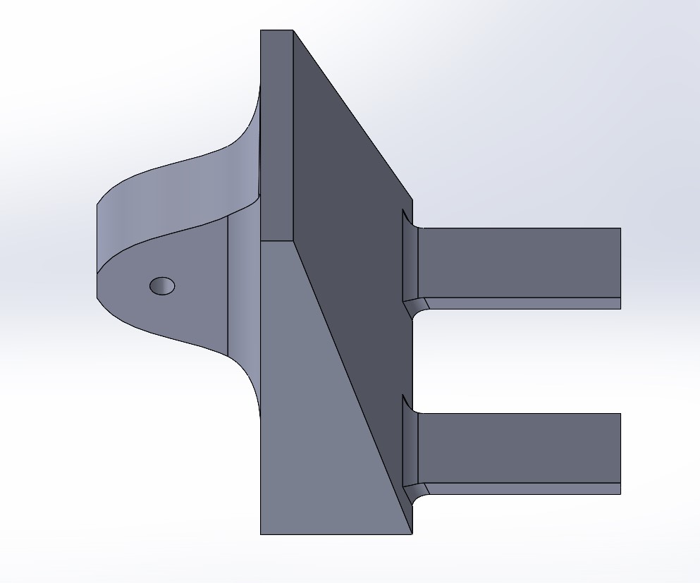
So, I saved myself from going through the trouble of making a motorized system have the exact same dynamics as a spring-mass system and thought about how I could rig a spring to support the arm in the way I desired. I found springs in EDS with about the spring constant I wanted (empirically speaking; I didn't know the exact spring constant, but they were close enough that it was worth a shot). I also didn't know exactly where on the arm I'd be attaching the springs, so I wanted whatever I designed to have multiple possible mounting locations for the springs. A little bit of CAD later, and I had this:
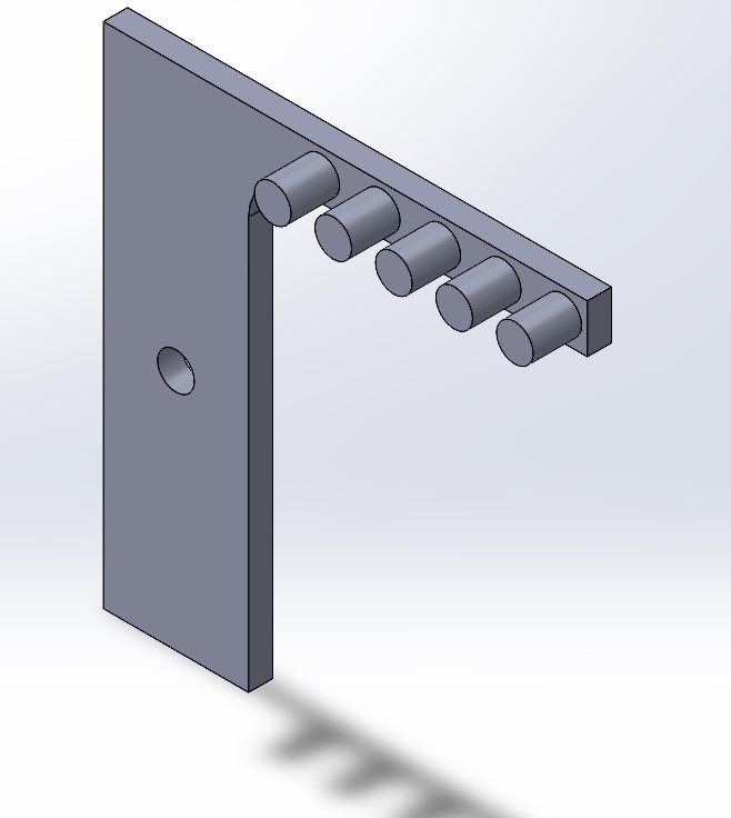
This apparatus, hereinafter referred to as the spring cage, would attach to the mount via the elbow joint, with its base flush with the ground so it doesn't rotate, and the springs could hang from any of the pins protruding from the side. I wanted to test this ASAP, so I started two prints, one of this device and another of its mirror image.
After the base and spring cages finished printing, I set up the system as a whole for the first time, attaching the springs first by zip-tying them around the arm bone so as not to make a permanent change. One spring wasn't quite enough to hold it the way I wanted. A second, shorter spring going from the backmost pin on each side did the trick. Once I confirmed the springs' locations, I drilled small holes through the sides of the arm joints and zip-tied the springs to them. There was, however, one big problem:
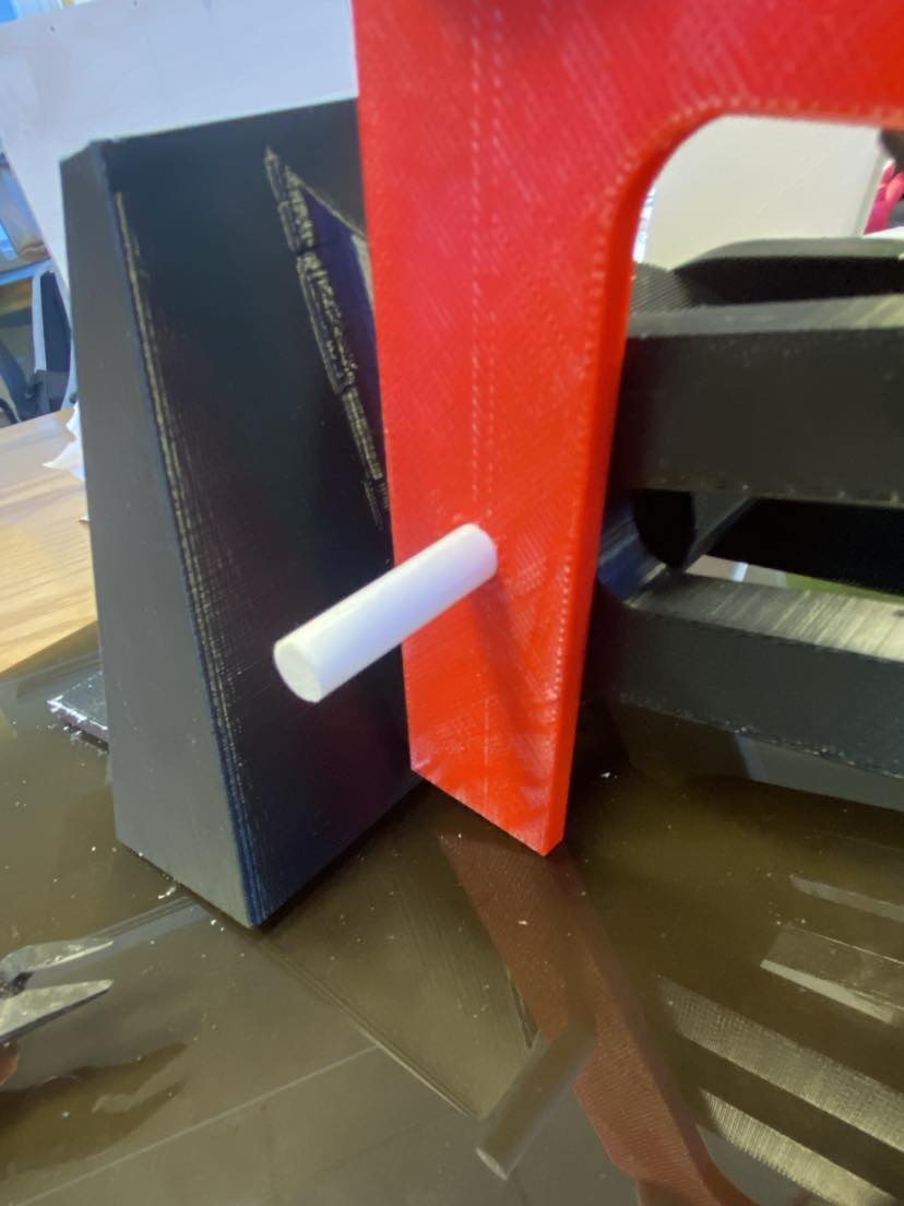
I was sure that I had designed it correctly, though. Upon further inspection of the CAD, I saw this:
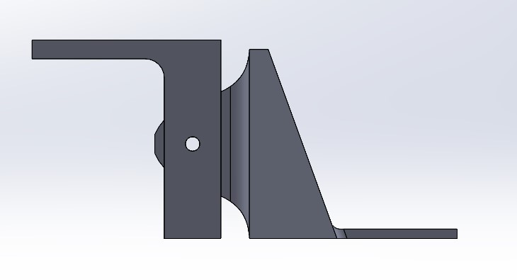
I'm still not fully sure what happened; no support material was left at the bottom of the base and it appeared to line up in the Solidworks assembly when viewed from the horizontal axis, but the disparity was consistent between both sides of the spring cage. Either way, I had to fix it. I decided to duct tape it down - I was taping down my base anyway, so it wouldn't be too bad to do this too. I inserted my sensor into the hand, connected everything together, and was ready to test my system that looked like...
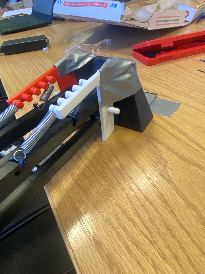
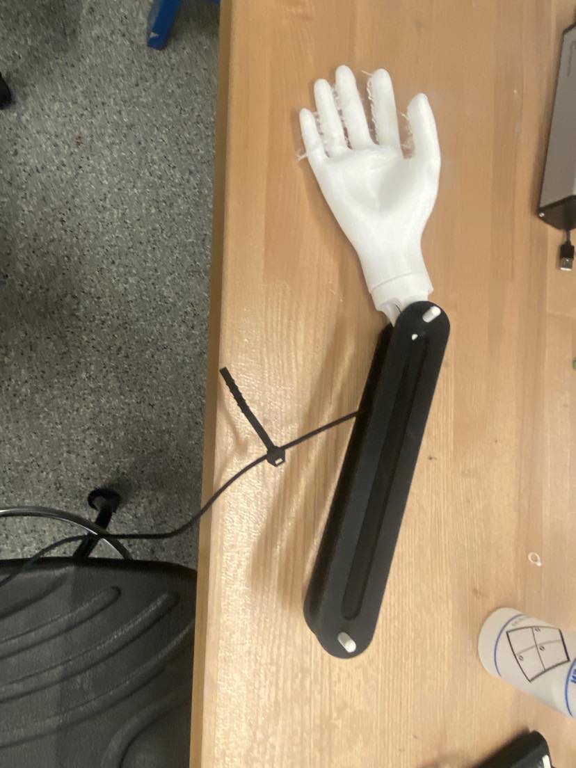
...that. I did not want to show up at the project presentation with something that looked like this. Throughout this project, I've taken pride in my design and implementation; nearly every part of this project was designed by me and together they looked very cleanly packaged. This, alongside Anthony's encouragement ("I think Neil would appreciate you finding a different way to hold everything together") motivated me to rethink it. I decided to laser cut a stock piece of acrylic in half, bolt down the base, add feet to the acrylic so it wouldn't slide, and glue small nuts between the base and the spring cage as rotation stoppers. As this entire process was done when I was very tired, I don't have pictures of every step, but I have pictures of the completed system:
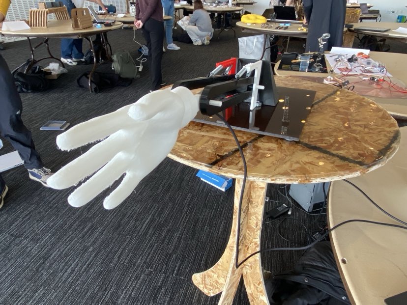
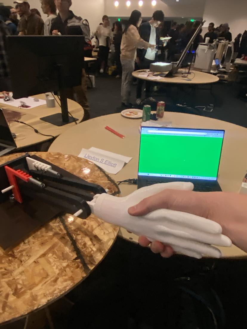
This makes for a good segue into presentation day! I had brought over my table from Week 8 to place the arm on, and was ready to do the final testing and calibration I'd do before showing my project to the world (well, HTMAA students, staff, and friends, close enough to the whole world). I made sure the minimum and maximum sensor values were correctly set up in my microcontroller code, checked that the Python script was correctly receiving the data over serial and that the JSON file was being updated, and that the webpage I used for my interface was working. That last item caused me some trouble; I found that Google Chrome worked better than any other browser when trying to access the webserver (not sure if this underwent enough trials to be considered statistically significant data, but Chrome messed up fewer times than the other ones I tried) and that I couldn't let my laptop go to sleep whilst running it or I'd have to reset/reconnect everything. Had I more time, I'd love to dig a little deeper because this kind of thing is not something with which I'm too familiar, but an hour or so out from the presentation, a "how not to break the project" protocol was enough for me.
Otherwise, everything worked great together and my project was ready to go! It does feel like a lot of things worked on the first try (or first try plus a quick fix), but I really do owe that success to the time and care I put into each stage of the design process. Things fit together when you go to great lengths to ensure they will before waiting for them to 3D print, and a long path of information stays intact when you verify that every step along that path is functioning as expected. This project really is the best example to date of me individually tackling something with a lot of moving parts (figuratively and kind of literally), and I'm quite proud of myself for keeping my head on straight through it all and getting it to work nicely.
I know a video exists of me giving the presentation to Neil and the class, but I've yet to obtain it, so in the meantime please enjoy this short video of Ty testing out my project: