Week 9 Assignment: Add a Sensor to a Microcontroller Board that you have Designed and Read It
This week began with a redesign of my development board from Weeks 5 and 6. For that assignment, I made a board without any connector pins on it, so I wanted to make a more general-purpose board with which I could mix and match components.
I also specificially wanted to use a force sensor, which I'll need in my final project. Anthony pointed me to Robert Hart's tutorial on capacitive sensing using a step response. Essentially, two pins of the board are each attached to an electrode of a capacitor. One of the pins sends a digital signal to its electrode that alternates between HIGH and LOW. The other pin reads the analog signal from its electrode, calculating and outputting the difference between the HIGH and LOW signals. The closer the electrodes, the higher the difference, and so the system's output is directly correlated to the compression force applied. This design is very nice for me, as I don't need exact force values in Newtons, I only need a signal that changes based on the force, the limits/bounds of which I can derive empirically. Also, there are many different ways to design the physical capacitor, allowing me flexibility in my final design. Hart's diagram of the setup is shown below:
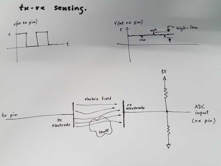
There was one design element I needed to add to my PCB based on this: the two resistors (which should each be a Megaohm or larger) needed to be connected to power (Not 5V but 3.3V in my case as I am using a Seeed Xiao RP2040) and ground in parallel with the analog pin. I then put some connectors into a schematic on KiCAD. I decided to have three each of 3.3V, 5V (unneccessary in hindsight, this board will get a redesign later), and GND pins, plus two LEDs directly on the PCB, with every other pin corresponding to a digital pin of the Xiao board. I finally added the resistors and had this schematic:
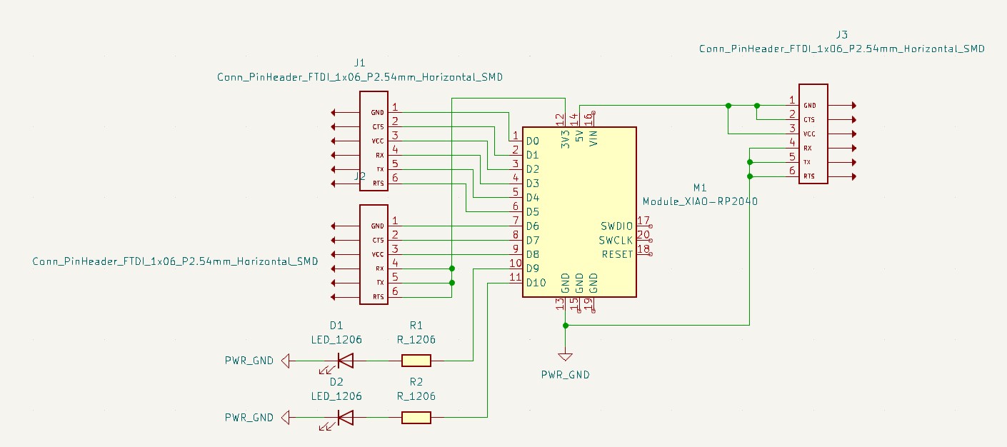
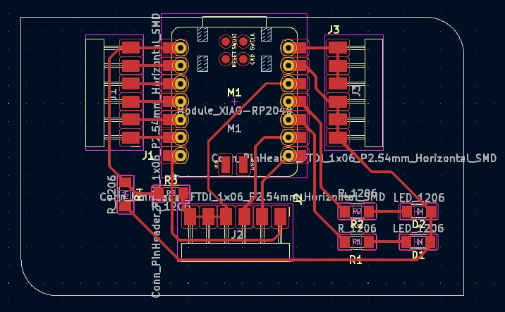
At this point, I'm definitely more comfortable with KiCad's PCB design interface, from how to set up my design rules and ensure I'll have a working PCB to minimizing the number of crossings/optimizing the path of all of the wires. In this case, only one crossing was necessary, and I already had a resistor in that path so it worked out really nicely.
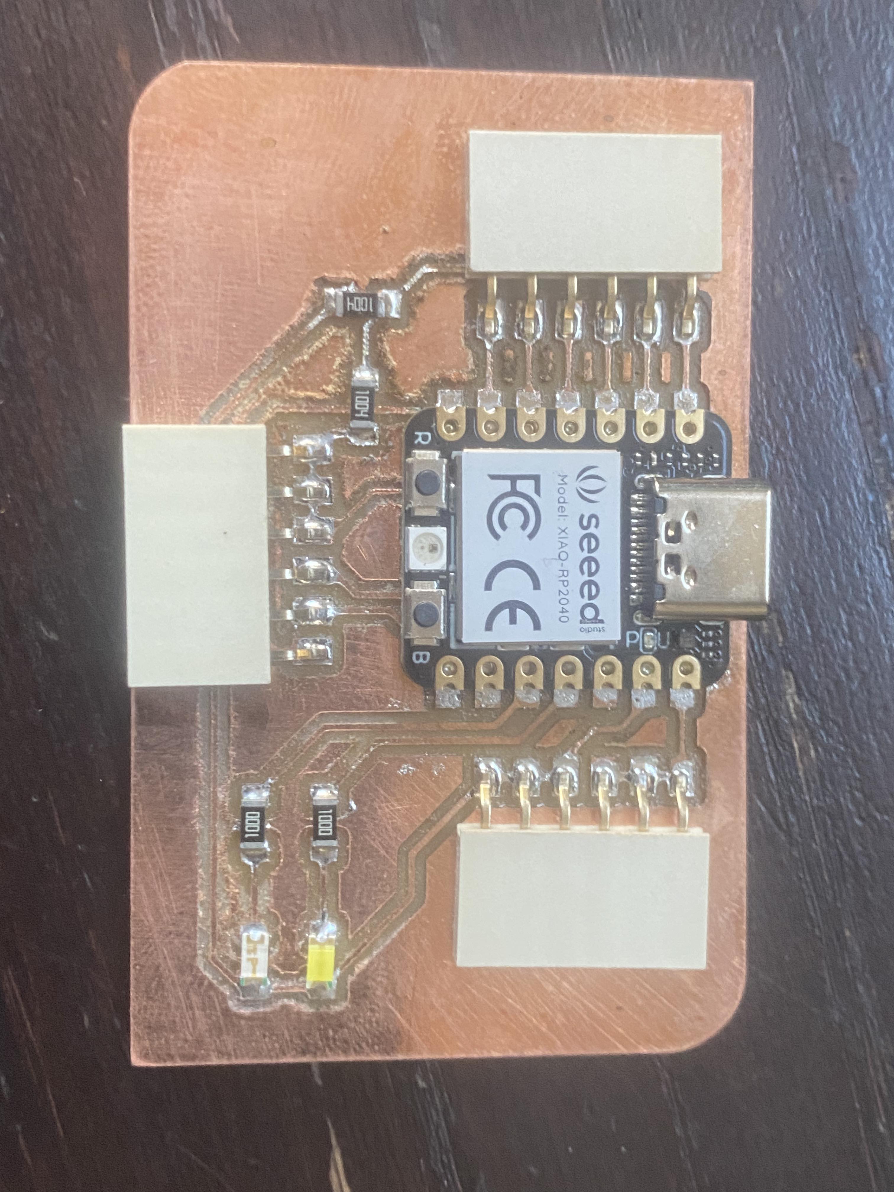
After some milling, sanding, and soldering, my new PCB was ready to go:
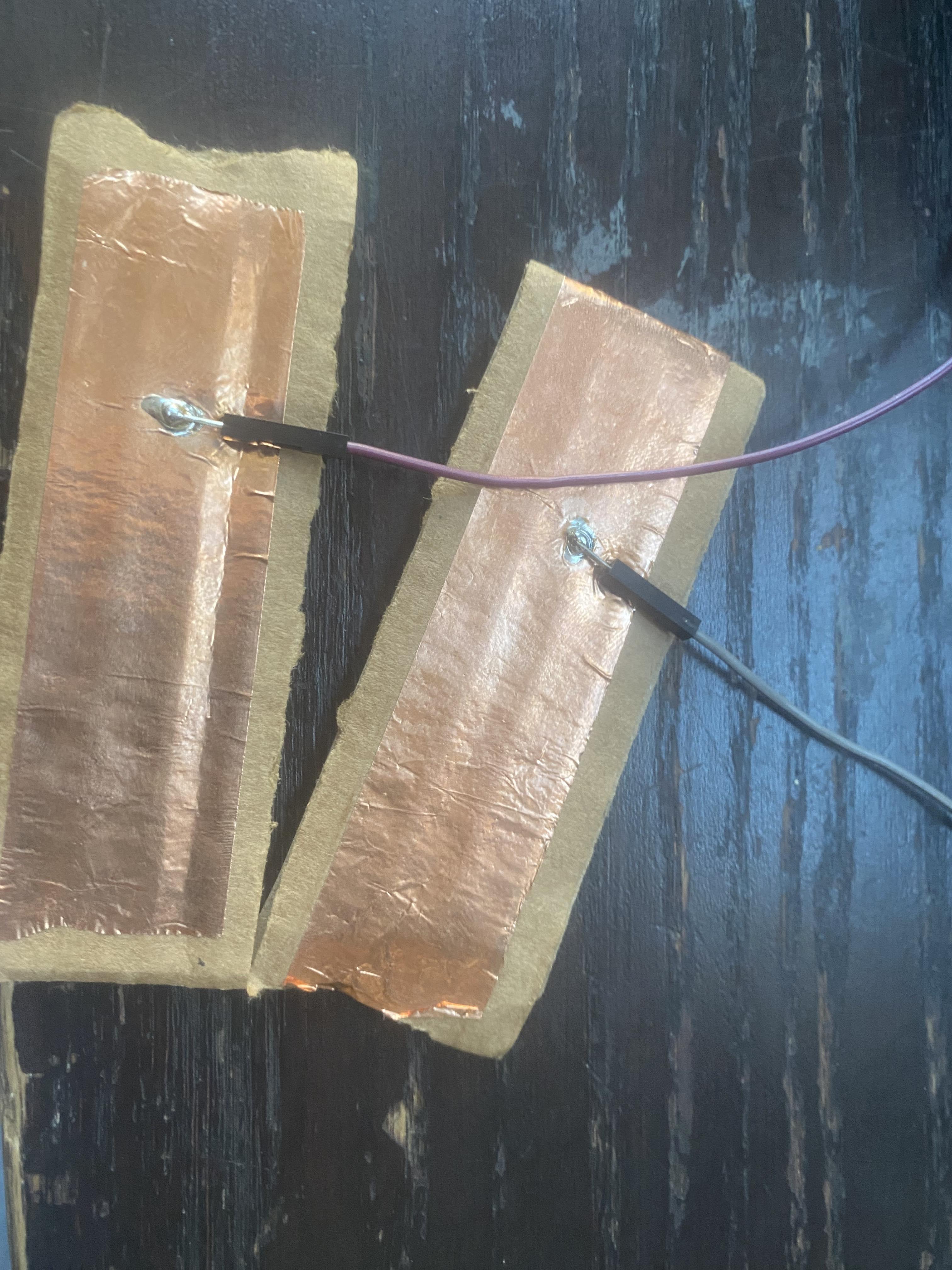
The next step was to actually make the sensor. For this week on a time crunch, I just wanted to prove I could get relevant results that varied with force. I soldered jumper wires to copper tape on cardboard (my electrodes) and attached them to pins 0 and 1 of my breakout board. I then put a springy/squishy material between them (in this case, it was actually just a foam-like piece of a fan filter from the back room).
All that was left (I thought) was to run a slightly modified version of Robert Hart's code, where I increased the number of samples before each output to see a more clear causal relationship.
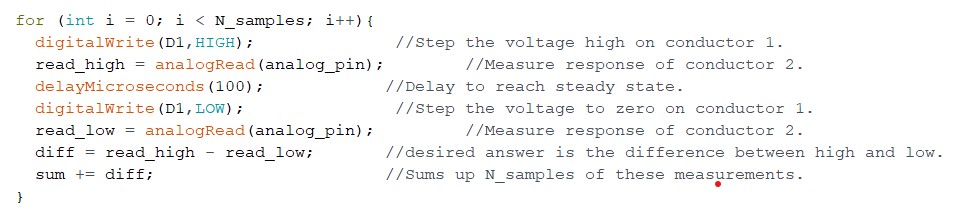
I was getting erratic signals that made very little sense to me, even becoming negative at some points. I talked to Anthony and we diagnosed it as a combination of noise and overflow values. He showed me how to overclock the microcontroller in the Arduino IDE (what I use to edit and upload code to the Xiao RP2040) and then it worked quite well! The output values at this point are quite arbitrary, but the graph below shows the effects of me pushing up and down on my makeshift capacitor.
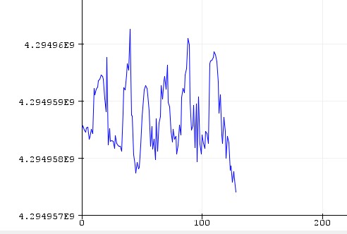
I had statistically relevant results! This is exactly what I had hoped for this week; there will be a very similar sensor in my final project and I have a good sense of at least one workflow for making it work, and it was also very nice to get a second go of PCB design. Thus concludes input device week.