Idea
Build a Lock State Device
Living in New House Dorm is nice, as you get the option os using single-stall bathrooms - the closest thing to living in an apartment. But because it is single-stall, it is always occupied in rush hours. So, I wanted to know, from the comfort of my room, whether the restroom is occupied or not using a light transistor that senses the lock position.
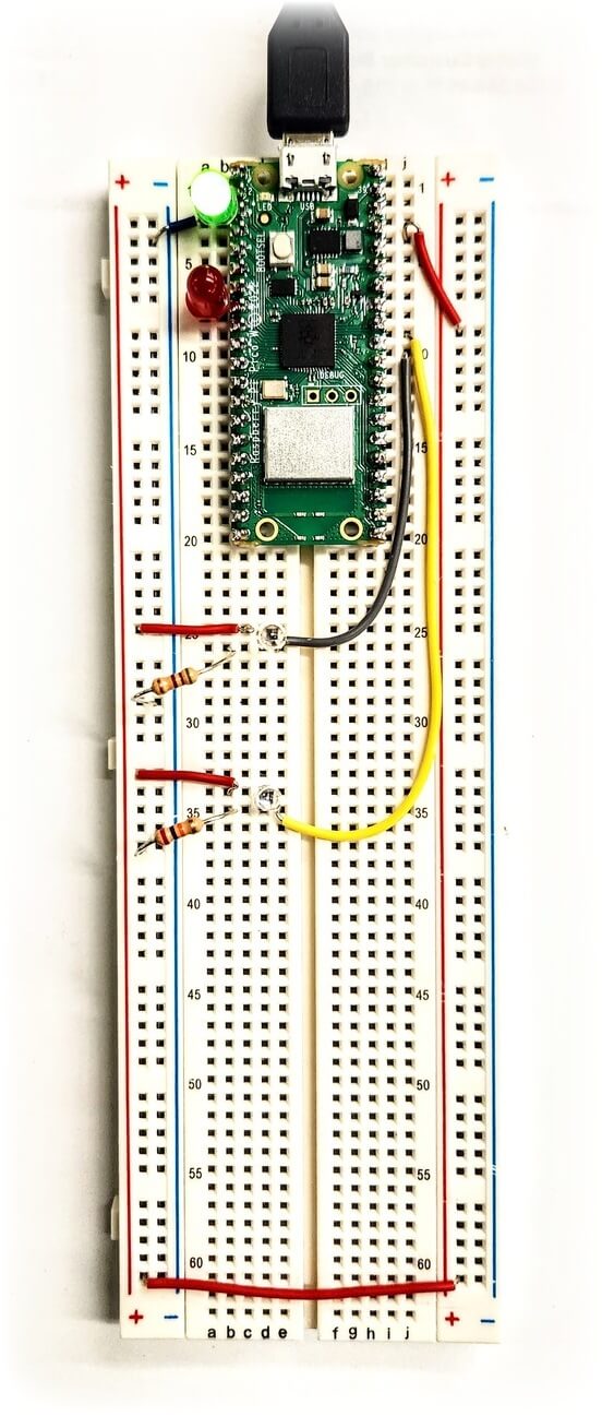
Circuit
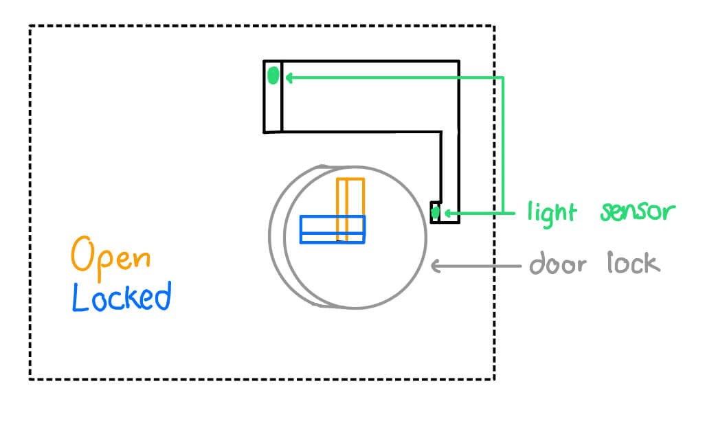
It is a simple circuit with two phototransistors. One to sense whether the bathroom light itself is open, as
the light closes automatically. Another to sense the lock position. There is also some LEDs for visual feedback.
There are two phototransistors, one for the room and one for the lock. The restroom light automatically turns on
using a motion sensor. There is one case when the restroom is occupied, which is when the restroom light is ON and
the lock is ON. The phototransistors then both should pick up plenty of light because of the
setup of the device.
Programming
It includes multiple of components, which is to monitor the input (light transistors) and control the output (LEDs) and to communicate through WiFi. I tried two chips, Seeed XIAO RP2040 and Raspberry Pi Pico 2040.
Seeed XIAO RP2040
Then, I switch back to C and used the RGB feature of the board to create a Rainbow Fade Transition.
ON/OFF LEDs
import time
from machine import Pin

# Define the pins for the LEDs
red_led_pin = Pin(17, Pin.OUT)
green_led_pin = Pin(16, Pin.OUT)
blue_led_pin = Pin(25, Pin.OUT)

# Function to turn on the LEDs
def turn_on_leds():
    red_led_pin.value(1)    # Turn on the red LED
    green_led_pin.value(1)  # Turn on the green LED
    blue_led_pin.value(1)   # Turn on the blue LED

# Function to turn off the LEDs
def turn_off_leds():
    red_led_pin.value(0)    # Turn off the red LED
    green_led_pin.value(0)  # Turn off the green LED
    blue_led_pin.value(0)   # Turn off the blue LED

# Main loop
while True:
    turn_on_leds()
    time.sleep(1)  # LEDs stay on for 1 second
    turn_off_leds()
    time.sleep(1)  # LEDs stay off for 1 second
First, I explored using MicroPython to code the device using a simple blinking LED example.
Rainbow Fade RGB
#include <Adafruit_NeoPixel.h>

int Power = 11;
int PIN  = 12;
#define NUMPIXELS 1

#define VIOLET 0
#define INDIGO 1
#define BLUE 2
#define GREEN 3
#define YELLOW 4
#define ORANGE 5
#define RED 6
#define BLACK 7
#define TRANSITION 10

int color = 0;
int old_time = 0;
int r = 255;
int g = 0;
int b = 0;

Adafruit_NeoPixel pixels(NUMPIXELS, PIN, NEO_GRB + NEO_KHZ800);

void setup()
{
    pixels.begin();
    pinMode(Power,OUTPUT);
    digitalWrite(Power, HIGH);
    Serial.begin(9600);
    old_time = millis();
    color = VIOLET;
}


void loop() {
    change_color();
}

void change_color() {
    switch(color) {
    case VIOLET:
        if(millis() >= old_time + TRANSITION) {
        old_time = millis();
        if(r>148) r = r - 1;
        if(b<211) b = b + 1;
        }
        if(r==148 && g==0 && b==211) {
        color = INDIGO;
        }
        break;
    case INDIGO:
        if(millis() >= old_time + TRANSITION) {
            old_time = millis();
            if(r>75) r = r - 1;
            if(b>130) b = b - 1;
        }
        if(r==75 && g==0 && b==130) {
            color = BLUE;
        }
        break;
    case BLUE:
        if(millis() >= old_time + TRANSITION) {
            old_time = millis();
            if(r>0) r = r - 1;
            if(b<255) b = b + 1;
        }
        if(r==0 && g==0 && b==255) {
            color = GREEN;
        }
        break;
    case GREEN:
        if(millis() >= old_time + TRANSITION) {
            old_time = millis();
            if(g<255) g = g + 1;
            if(b>0) b = b - 1;
        }
        if(r==0 && g==255 && b==0) {
            color = YELLOW;
        }
        break;
    case YELLOW:
        if(millis() >= old_time + TRANSITION) {
            old_time = millis();
            if(r<255) r = r + 1;
        }
        if(r==255 && g==255 && b==0) {
            color = ORANGE;
        }
        break;
    case ORANGE:
        if(millis() >= old_time + TRANSITION) {
            old_time = millis();
            if(g>127) g = g - 1;
        }
        if(r==255 && g==127 && b==0) {
            color = RED;
        }
        break;
    case RED:
        if(millis() >= old_time + TRANSITION) {
            old_time = millis();
            if(g>0) g = g - 1;
        }
        if(r==255 && g==0 && b==0) {
            color = VIOLET;
        }
        break;
    }
    pixels.clear();
    pixels.setPixelColor(0, pixels.Color(r, g, b));
    pixels.show();
}
Raspberry Pi Pico W
As I reached the limitation of Seed Ciao RP2040 in term of communication capabilities, I started learning how to use Raspberry Pi Pico W.
Light Sensor Monitor
#include

#define room_sens_pin 26
#define lock_sens_pin 27

#define RED_LED 5
#define GREEN_LED 1

#define ON_CUTOFF 8.5

Smoothed <float> roomSens;
Smoothed <float> lockSens;


void setup() {
    Serial.begin(9600);
    pinMode(room_sens_pin, INPUT);
    pinMode(lock_sens_pin, INPUT);
    pinMode(RED_LED, OUTPUT);
    pinMode(GREEN_LED, OUTPUT);
    roomSens.begin(SMOOTHED_AVERAGE, 5);
    lockSens.begin(SMOOTHED_AVERAGE, 5);
}

void loop() {
    float roomReading = analogRead(room_sens_pin);
    float lockReading = analogRead(lock_sens_pin);
    roomSens.add(roomReading);
    lockSens.add(lockReading);
    roomReading = roomSens.get();
    lockReading = lockSens.get();
    Serial.print("Room (up) Sensing");
    Serial.println(roomSens.get());
    Serial.print("lock (low) Sensing");
    Serial.println(lockSens.get());
    delay(100);

    if(roomReading > ON_CUTOFF && lockReading > ON_CUTOFF) {
    digitalWrite(RED_LED, HIGH);
    digitalWrite(GREEN_LED, LOW);
    } else {
    digitalWrite(RED_LED, LOW);
    digitalWrite(GREEN_LED, HIGH);
    }
}
The following code is to test WiFi Capabilities. Due to the limited time, I was not able to finish testing and
building the HTML to interact with the user and send data. The plan is to use the the Pico W as the server
and connect to it using its IP address. In its code, I will add the HTML page that will appear to the user
using client.println More things to learn and implement!
WiFi IP Address Printer
#include

// Replace with your network credentials
const char* ssid = "YOUR_SSID";
const char* password = "YOUR_PASSWORD";

void setup() {

// Start the Serial Monitor
Serial.begin(115200);

// Operate in WiFi Station mode
WiFi.mode(WIFI_STA);

// Start WiFi with supplied parameters
WiFi.begin(ssid, password);

// Print periods on monitor while establishing connection
while (WiFi.status() != WL_CONNECTED) {
    delay(500);
    Serial.print(".");
    delay(500);
}

// Connection established
Serial.println("");
Serial.print("Pico W is connected to WiFi network ");
Serial.println(WiFi.SSID());

// Print IP Address
Serial.print("Assigned IP Address: ");
Serial.println(WiFi.localIP());

}

void loop() {

delay(2000);

// Print IP Address
Serial.print("Assigned IP Address: ");
Serial.println(WiFi.localIP());

}
WiFi Interactive Page (uncompleted)
#include
// Replace with your network credentials
const char* ssid = "YOUR_SSID";
const char* password = "YOUR_PASSWORD";
// Set web server port number to 80
WiFiServer server(80);
// Variable to store the HTTP request
String header;
// Variable to store onboard LED state
String picoLEDState = "off";
// Current time
unsigned long currentTime = millis();
// Previous time
unsigned long previousTime = 0;
// Define timeout time in milliseconds (example: 2000ms = 2s)
const long timeoutTime = 2000;
void setup() {
// Start Serial Monitor
Serial.begin(115200);
// Initialize the LED as an output
pinMode(LED_BUILTIN, OUTPUT);
// Set LED off
digitalWrite(LED_BUILTIN, LOW);
// Connect to Wi-Fi network with SSID and password
WiFi.begin(ssid, password);
// Display progress on Serial monitor
while (WiFi.status() != WL_CONNECTED) {
delay(500);
Serial.print(".");
}
// Print local IP address and start web server
Serial.println("");
Serial.print("WiFi connected at IP Address ");
Serial.println(WiFi.localIP());
// Start Server
server.begin();
}
void loop() {
WiFiClient client = server.available(); // Listen for incoming clients
if (client) { // If a new client connects,
currentTime = millis();
previousTime = currentTime;
Serial.println("New Client."); // print a message out in the serial port
String currentLine = ""; // make a String to hold incoming data from the client
while (client.connected() && currentTime - previousTime <= timeoutTime) { // loop while the client's connected
currentTime = millis();
if (client.available()) { // if there's bytes to read from the client,
char c = client.read(); // read a byte, then
Serial.write(c); // print it out the serial monitor
header += c;
if (c == '\n') { // if the byte is a newline character
// if the current line is blank, you got two newline characters in a row.
// that's the end of the client HTTP request, so send a response:
if (currentLine.length() == 0) {
// HTTP headers always start with a response code (e.g. HTTP/1.1 200 OK)
// and a content-type so the client knows what's coming, then a blank line:
client.println("HTTP/1.1 200 OK");
client.println("Content-type:text/html");
client.println("Connection: close");
client.println();
// Switch the LED on and off
if (header.indexOf("GET /led/on") >= 0) {
Serial.println("LED on");
picoLEDState = "on";
digitalWrite(LED_BUILTIN, HIGH);
} else if (header.indexOf("GET /led/off") >= 0) {
Serial.println("LED off");
picoLEDState = "off";
digitalWrite(LED_BUILTIN, LOW);
}
// Display the HTML web page
client.println("");
client.println("");
client.println("");
// CSS to style the on/off buttons
client.println("");
// Web Page Heading
client.println("Pico W LED Control
");
// Display current state, and ON/OFF buttons for Onboard LED
client.println("Onboard LED is " + picoLEDState + "
");
// Set buttons
if (picoLEDState == "off") {
//picoLEDState is off, display the ON button
client.println("");
} else {
//picoLEDState is on, display the OFF button
client.println("");
}
client.println("");
// The HTTP response ends with another blank line
client.println();
// Break out of the while loop
break;
} else { // if you got a newline, then clear currentLine
currentLine = "";
}
} else if (c != '\r') { // if you got anything else but a carriage return character,
currentLine += c; // add it to the end of the currentLine
}
}
}
// Clear the header variable
header = "";
// Close the connection
client.stop();
Serial.println("Client disconnected.");
Serial.println("");
}
} Micropython vs C/C++
Having used Arduino before as it is widely used made starting to use new microprocessors smoother. All I had to do
to install the respective board manager and I am ready to go.
For Micropython, I had to install the language first using brew install micropython. Some people in
the internet were able to use VSCode to run Micropython using an extension, but that did not work for me. So, I
had to install a new IDE, Thonny, to run Micropython. After setting the laptop, you also have to download UF2 firmware
on the RP2040 to be able to code on it.
COM vs Drive
I learned that there are two ways to connect to RP2040, which is as a drive and a COM port. You can upload the firmware
only when it appears as a drive. To do so, hold on on the Bootload button while connecting. Note that this will erase
Micropython firmware on the microprocessor. You can use this to switch between C and Mircopython. Now, you can see it
in your file browser as a drive. You can also still upload code to it by Tools/Port/UF2 Board.
To connect it as a COM port, plug it normally. You can not upload any firmware in this state, but you can upload your code.
Assignment Description
Individual Assignments:
- browse through the datasheet for your microcontroller
- write a program for a microcontroller development board to interact (with local input &/or output) and communicate (remotely)
- extra credit: use different languages &/or development environments
- extra credit: connect external components to the board
Group Assignment:
- compare the performance and development workflows for other architectures. Get a feel for the different flavors and what might vibe with you
- Everyone should see Arduino and MicroPython with a XIAO. But beyond that there are other languages and toolchains (native C, Rust/Go, Javascript, ...), other processor families (AVR, SAMD, ...), and other architectures (FPGA, PLD, PIO, GPU, ...). Group goal is to sample options beyond what you're doing individually this week.