This was
The Fifth Project
Electronic Design
EDA!

Tools
Short list this week:- Fusion360 (EAGLE)
Process
This is the section where I am most unfamiliar with. Its been about 12 years since my last academic class into EE anything. After a few Youtube videos brushing up on basic electric principles, it was onto the Electronic DesignNow we started with the XIAO RP2040. Here we outlined a few items that I WANT to do. But because we need to plan on what we are doing, we will be doing them in logical sense to both accomplish the class AND make what we want to build. We started with the following specifics:
- Speakers - for outputting words
- Screen - for showing words / pictures
- LED lights - for segmenting Korean/English
- Battery - for allowing this to be done on the move (this will be done with a battery pack first)
- Microphone - for audio input
- Bluetooth Module - for phone pairing
- QI Charging - to be compatible with a "nest"
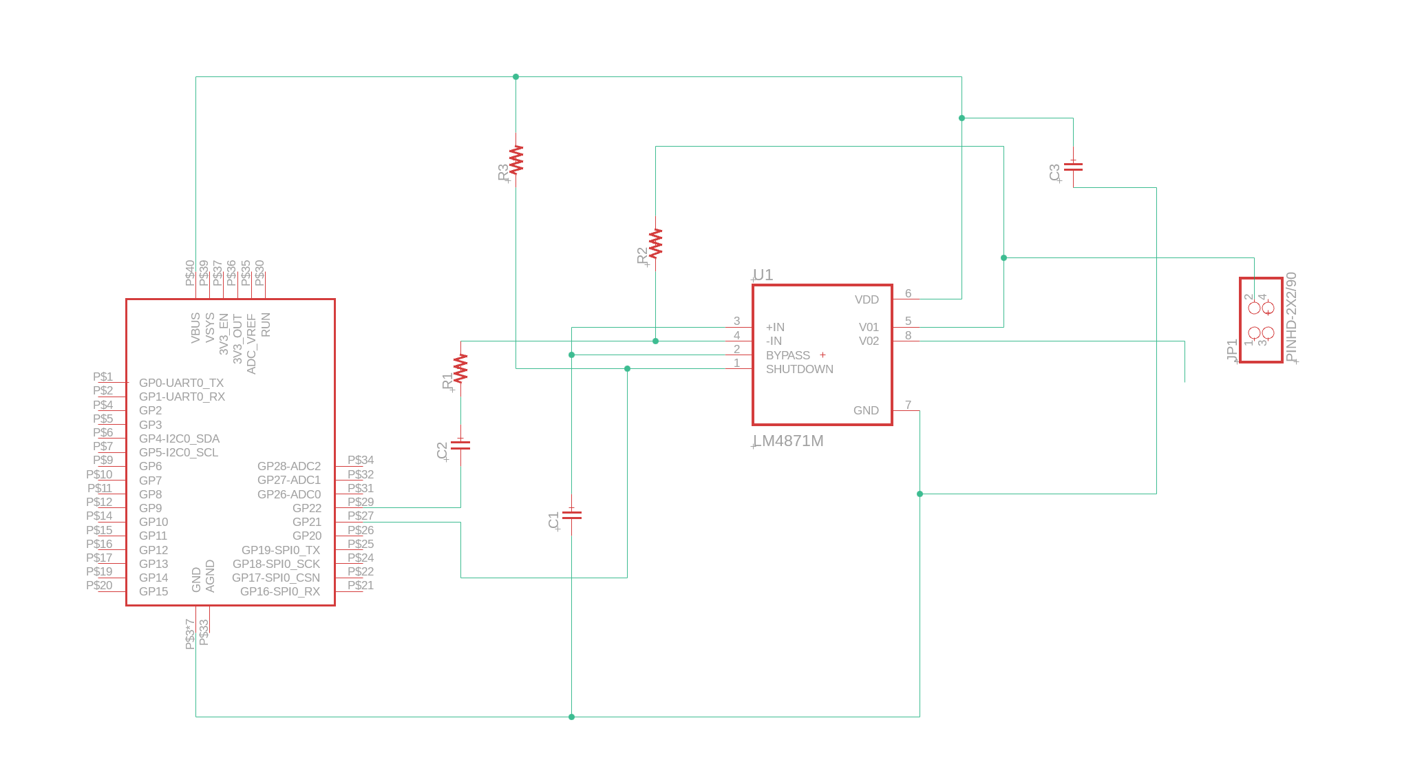
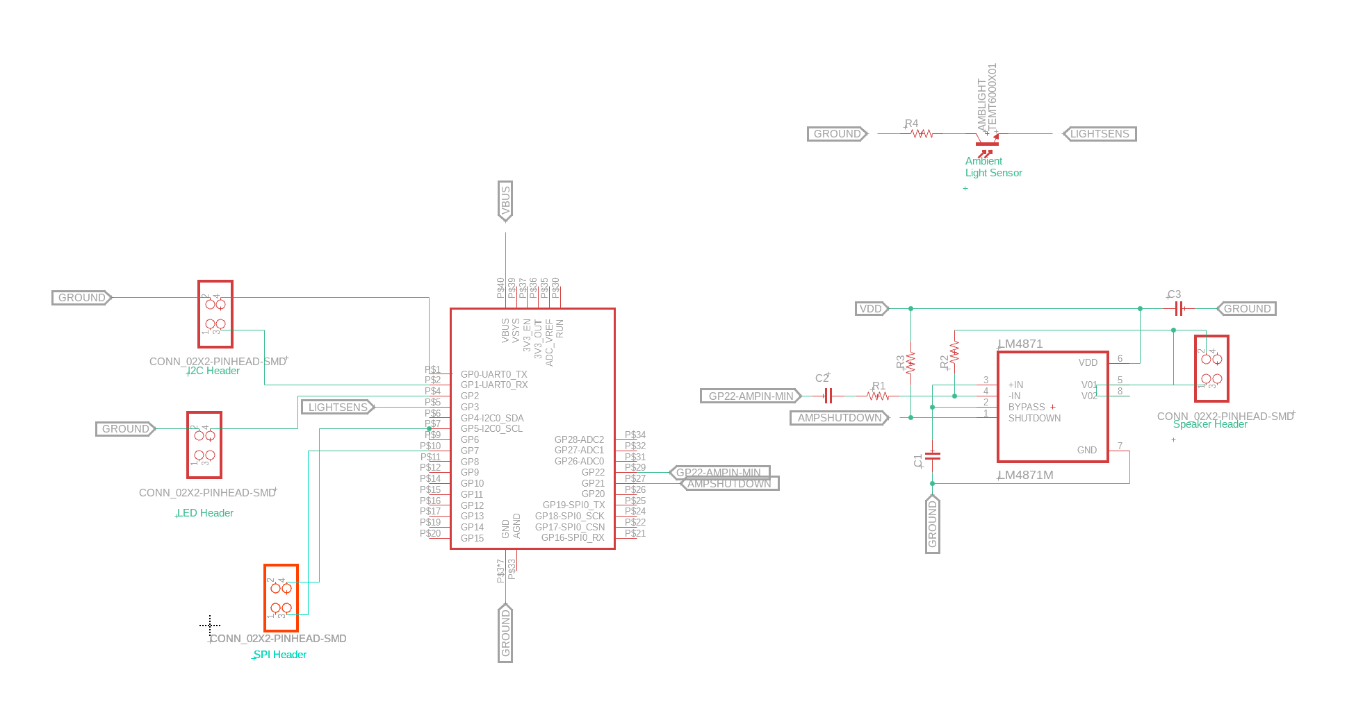
Our Schematic Diagram - First Pass
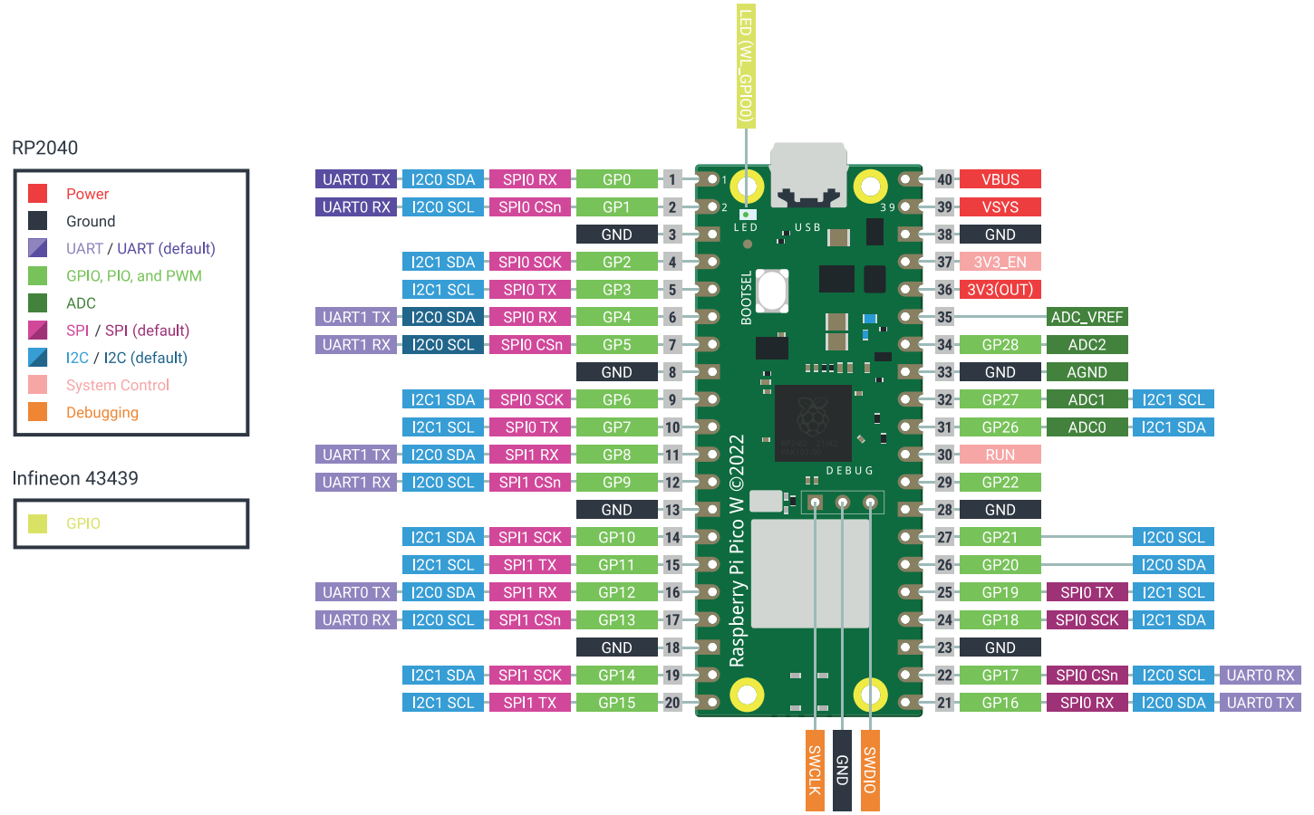
Even though we are still using the RP2040 (essentially), we need this PICO W diagram for everythgin else! We will use the right side of the board for the speakers (+mic - later) and the left side of the board for the screen and buttons. In order for us to get the board done - we need to add our driver for our speakers. We will be using the LM4871 - specifically the practical diagram https://www.ti.com/product/LM4871
Afterwards, lets work on the screen. Because we don't know what type of screen we want/have, we will wire up two header interfaces for both I2C and SPI headers. The PicoW has plenty for us to use. We will focus on the pins on the left side of the diagram to help physically plan out space. We can change the wiring if needed down the road.
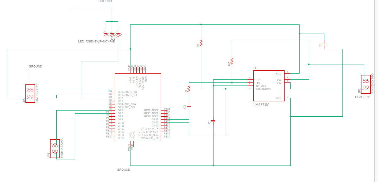
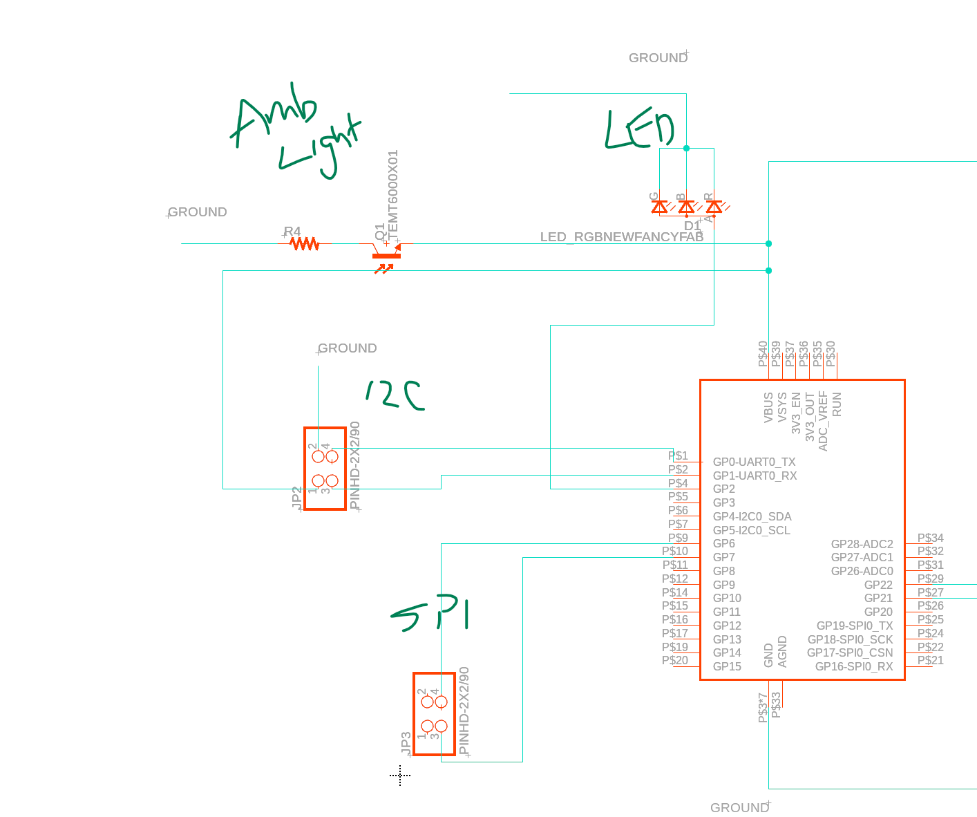
Some of the new modules
Top down (L to R )
- Amb Light Sensor
- LED Strip (TBD on how many)
- I2C header
- SPI header
Clean it up
For readability
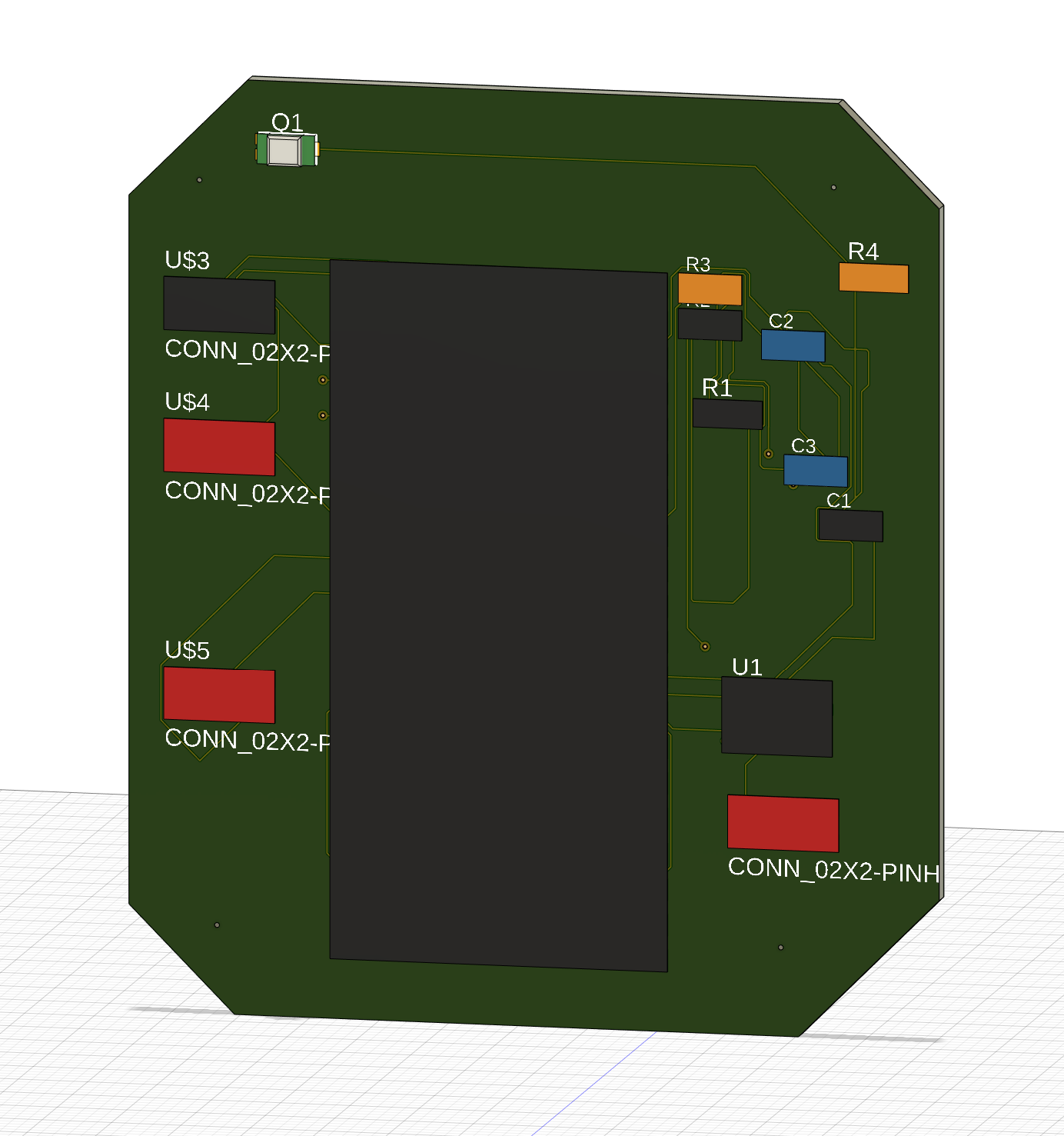
Now we can focus on building our board for next week. We use Fusion360 to translate out schematic to a PCB + CAD File.
Note: FabLab digital repositories did not have alot of associated CAD models, so the CAD doesnt show that well.
Final Output:

- © Untitled
- Design: HTML5 UP