Final Project - Modular Tool Storage
HomeBreakdown
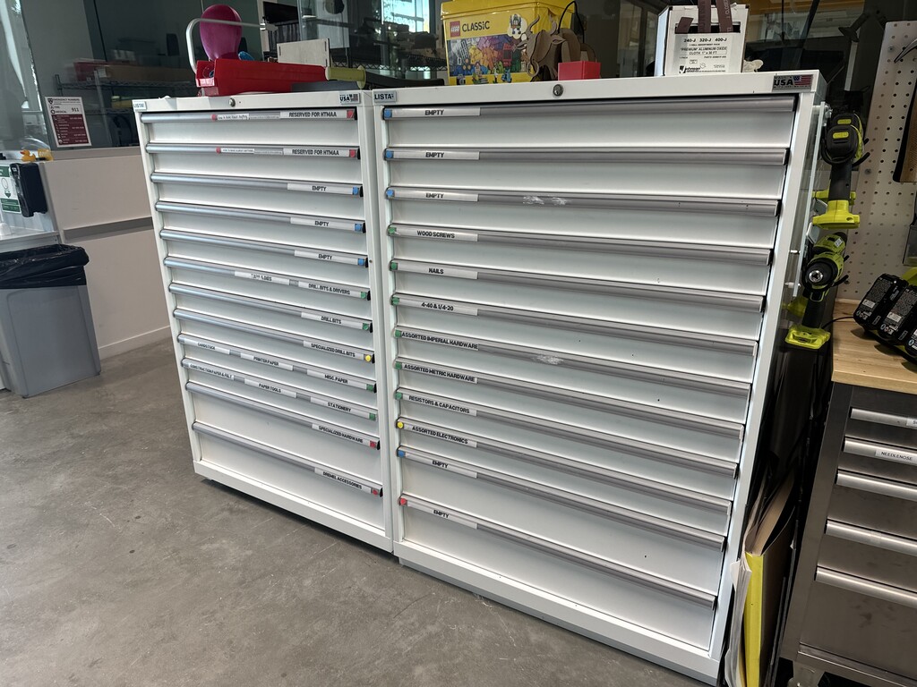
I have seen a lot of tool chests in my time. My dad has a tool chest at home, the makerspace I work at has a tool chest, and the theatre I work at has a tool chest!

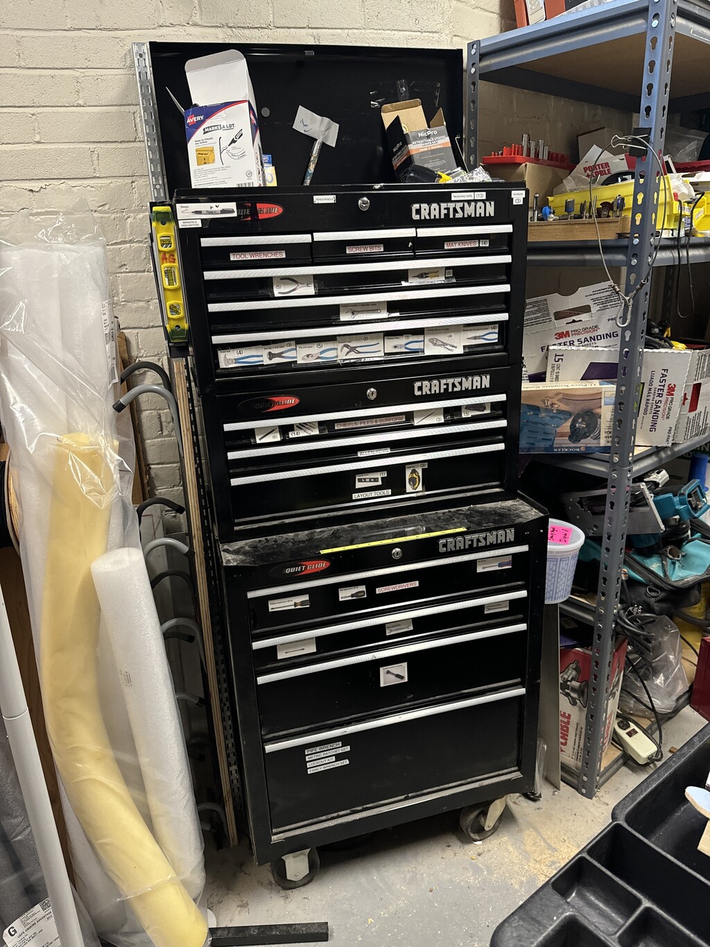
This summer, I organized my dad's toolchest, and the whole time I thought about how much easier it would be if I could know what exactly was in each drawer and just move drawers around easily.
This made me realize that I wanted to make a toolchest that could be easily used as a toolbox too via modularity!!
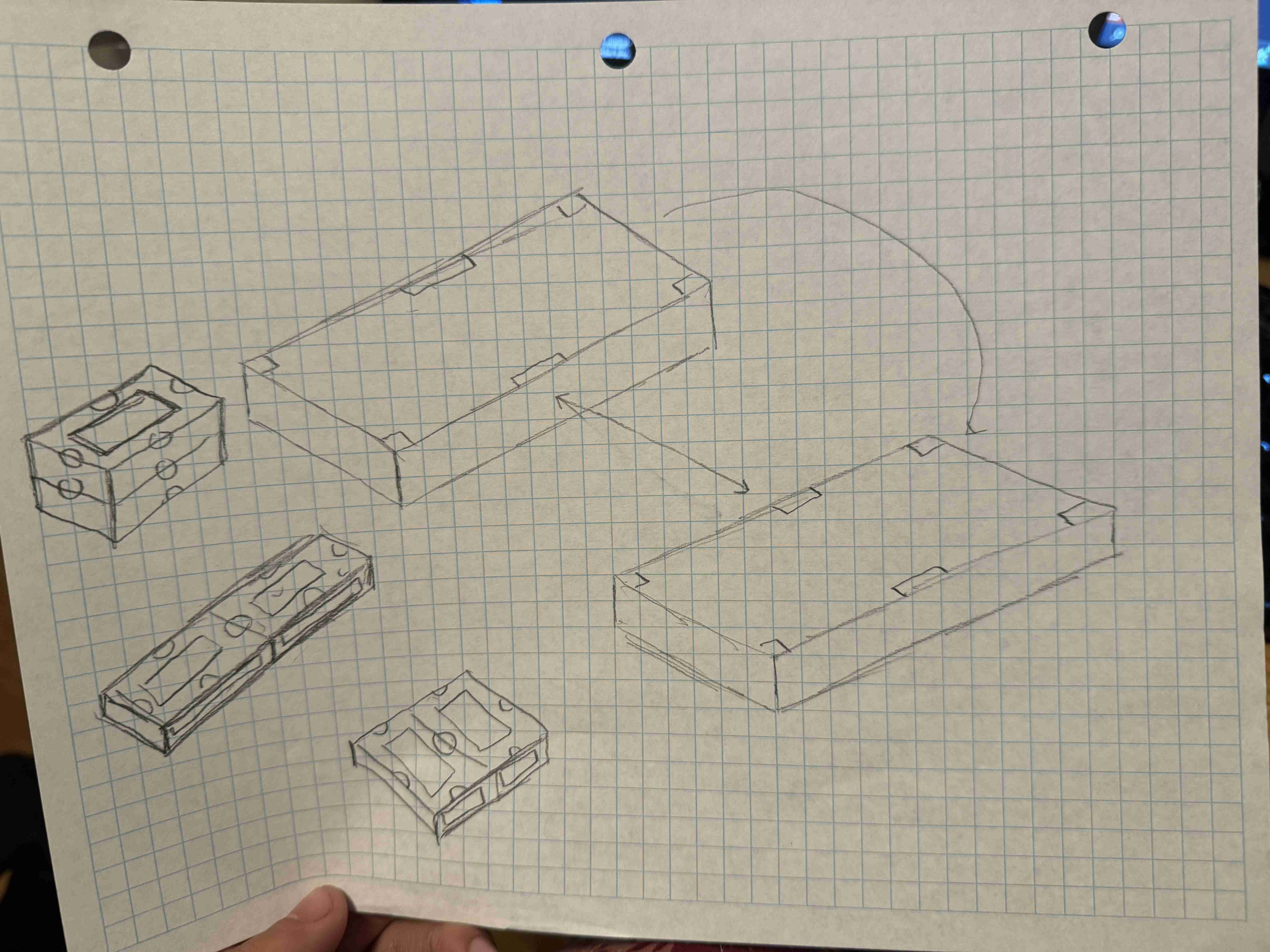
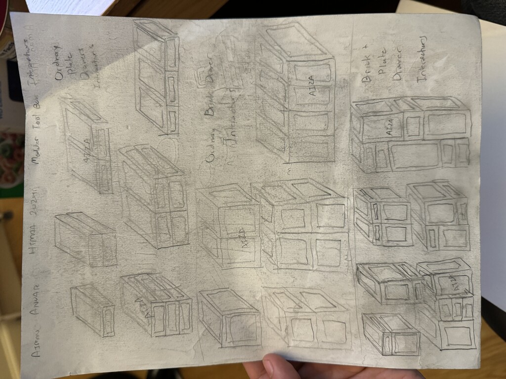
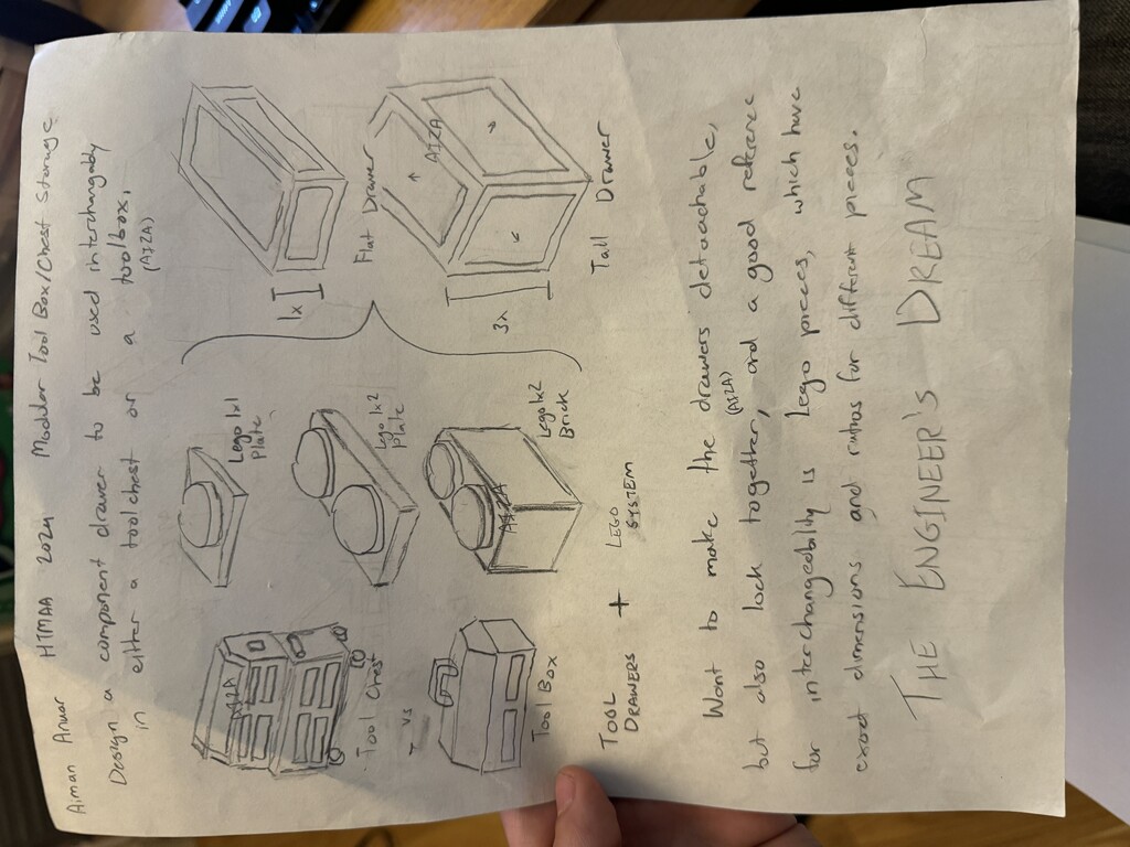
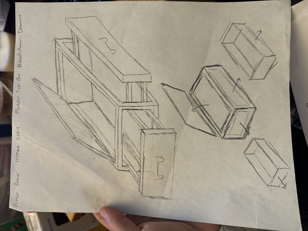
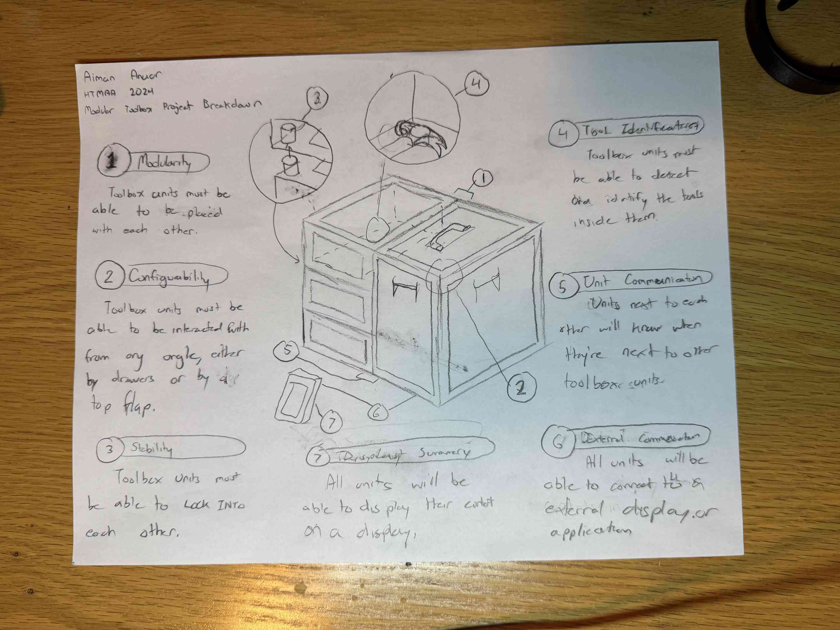
I first started with thinking about mainly what I wanted from the toolbox. I wanted it to interlock like Legos, so I designed it to have similar dimensions to Lego plates. I also thought about designing it to have electromagnets that activated when next to another toolbox. Here are my main drawings for it:
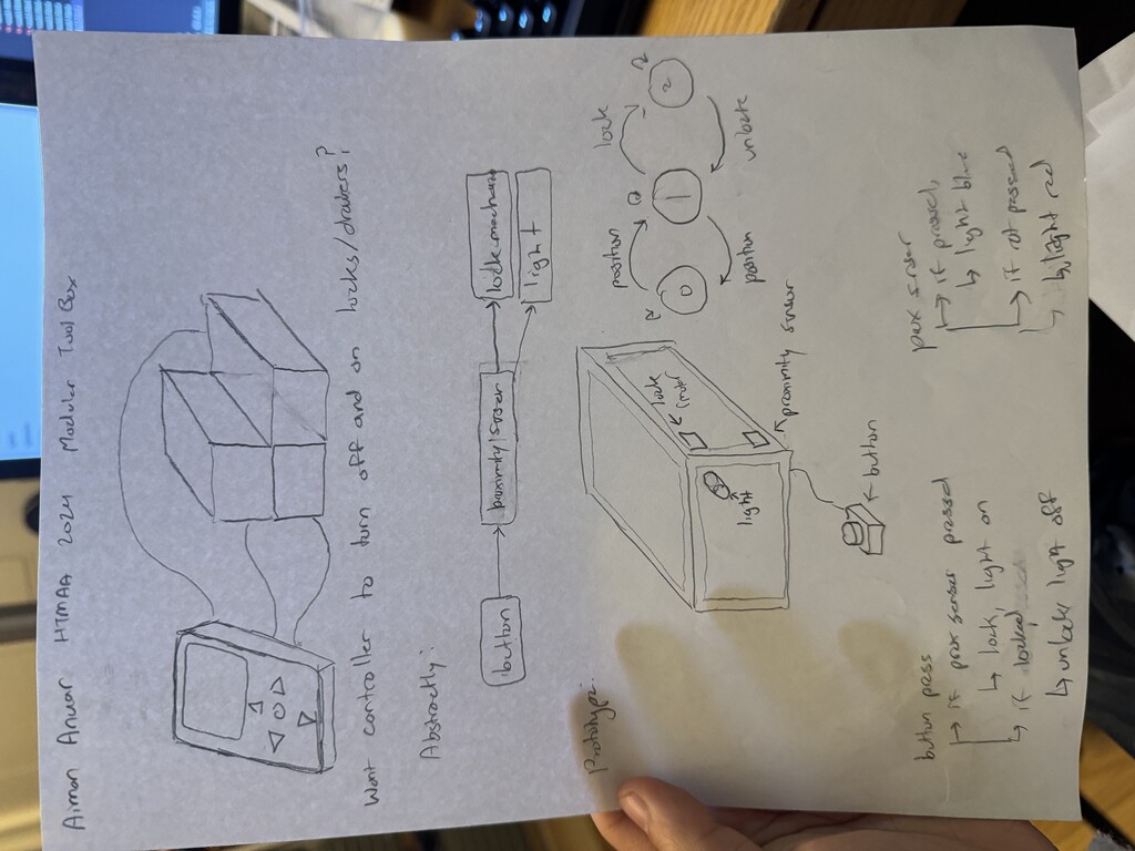
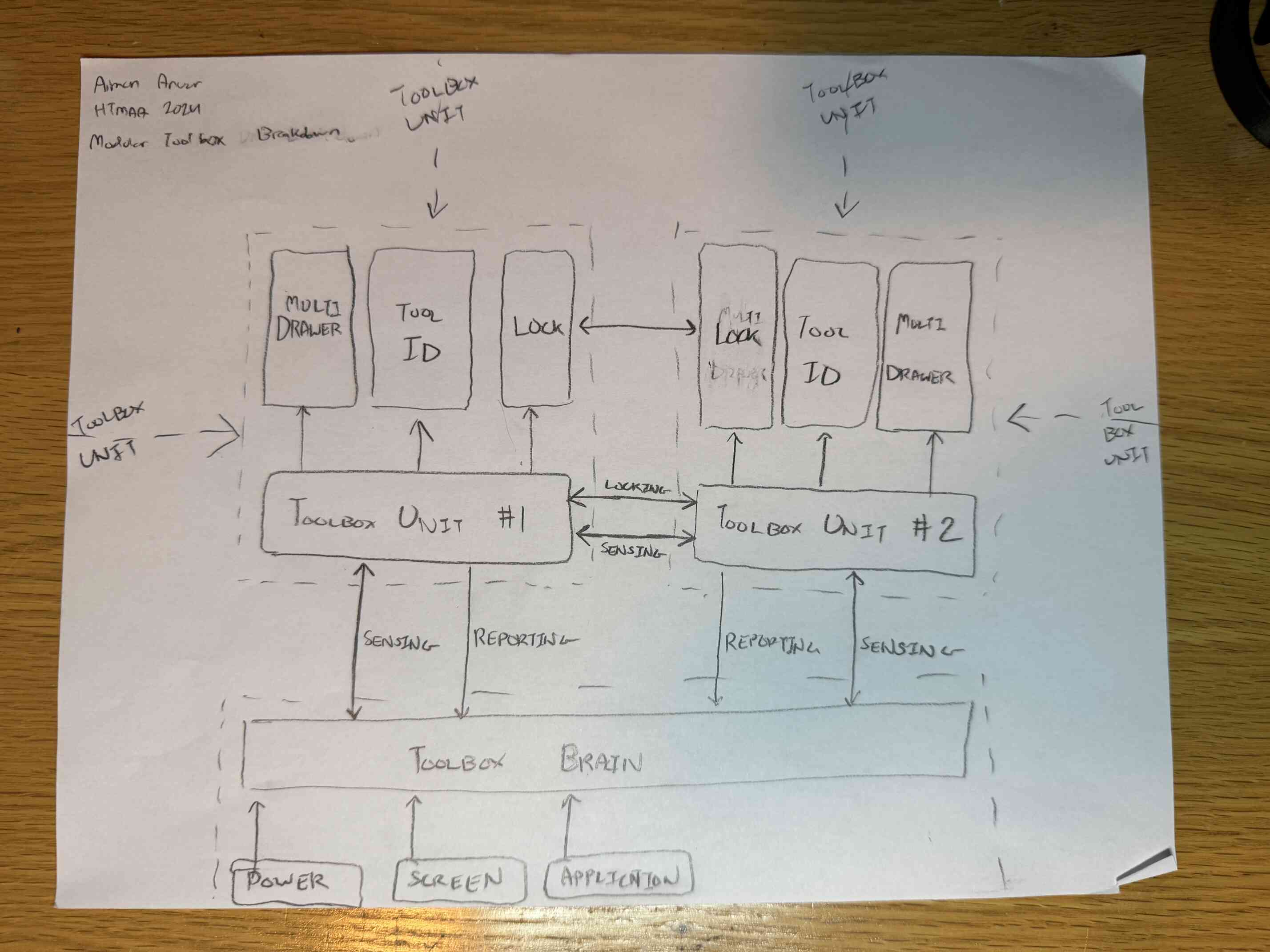
I further developed the system and how it would interact digitally and broke down exactly how the system was going to run and what priorities I had out of the design. Here are some more drawings of it:
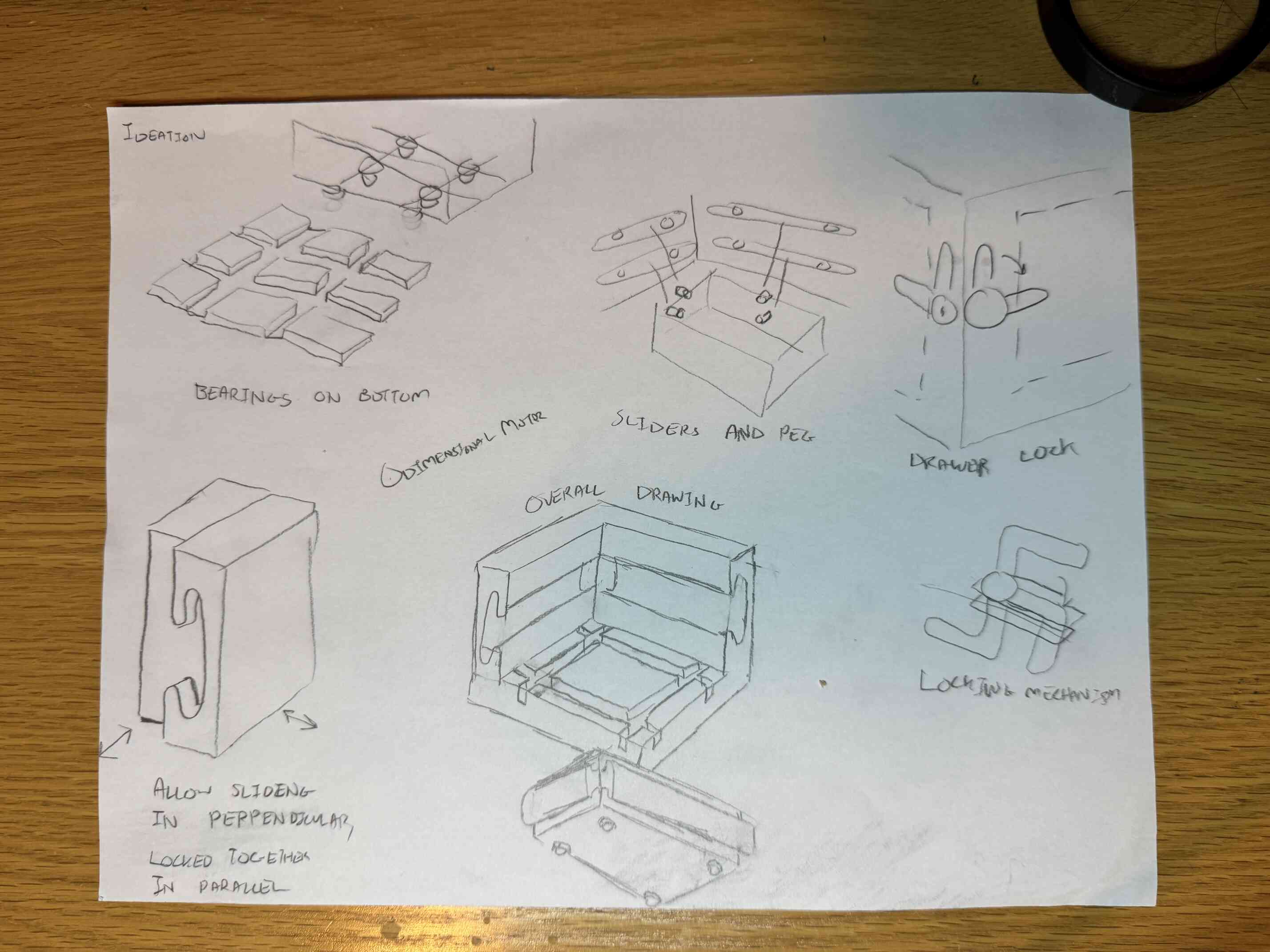
I started with trying to prototype an easily manufacturable two-way sliding mechanism, using ball bearings on the base. From doing this, I realized that while this could be my final goal, it was really not worth doing on a simple cardboard or wood box that wouldn't have much friction.
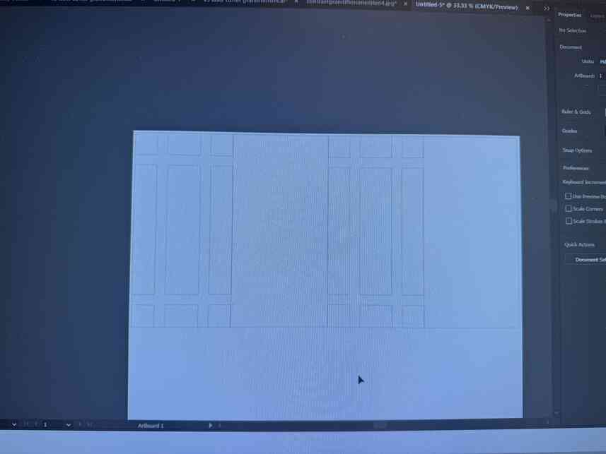
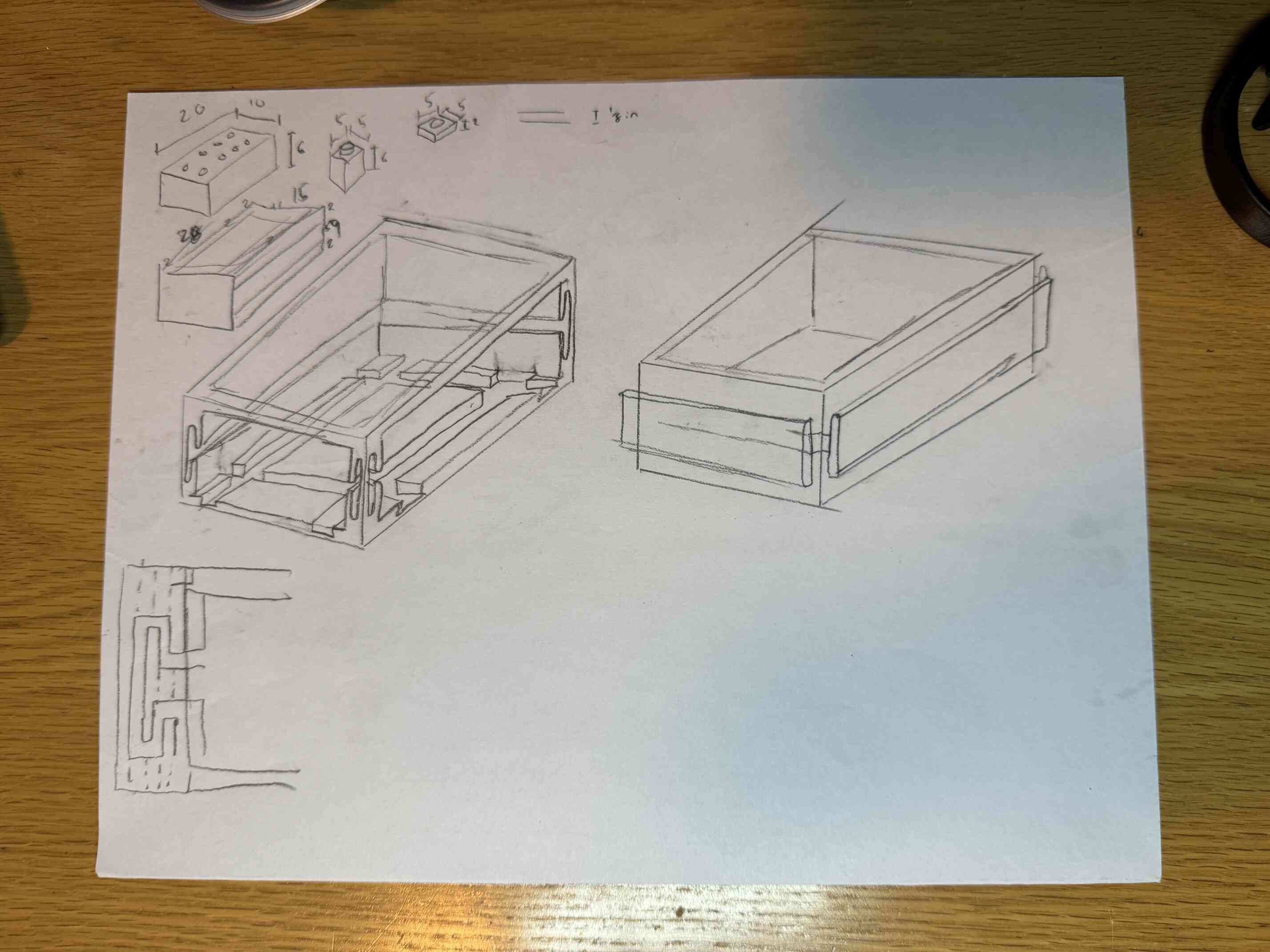
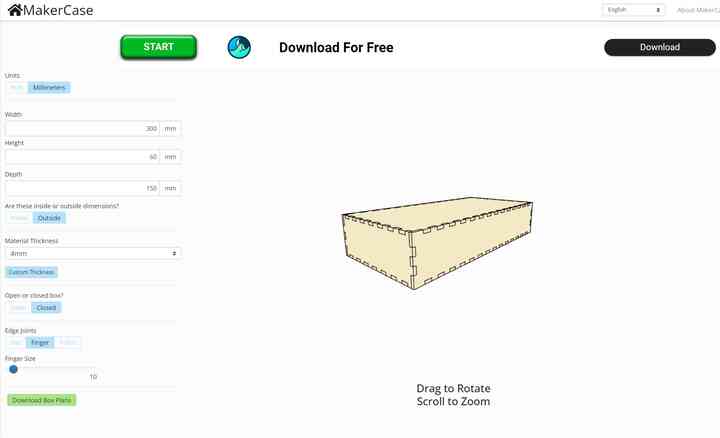
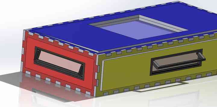
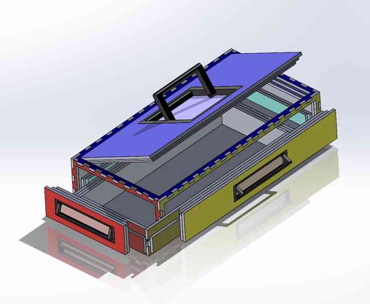
Then I tried to model the actual box in Solidworks! It required me to use MakerCase to generate the profile for a box with finger joints using kerf values from Week 2 and then import those drawings into SolidWorks.
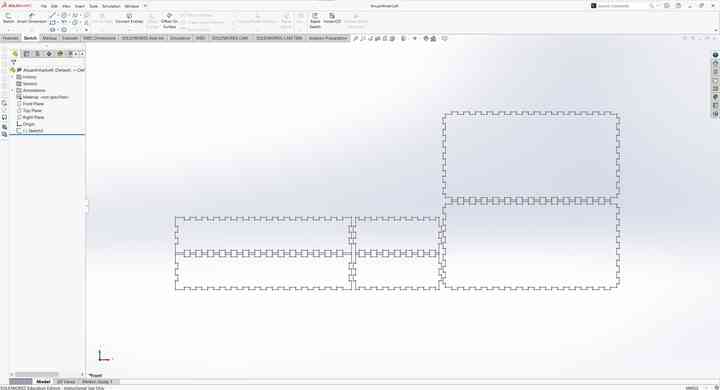
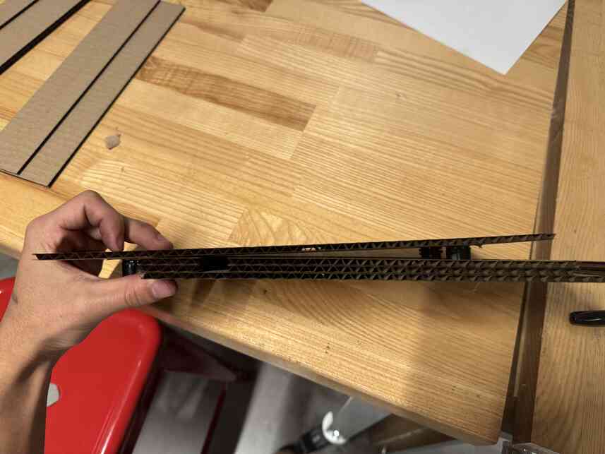
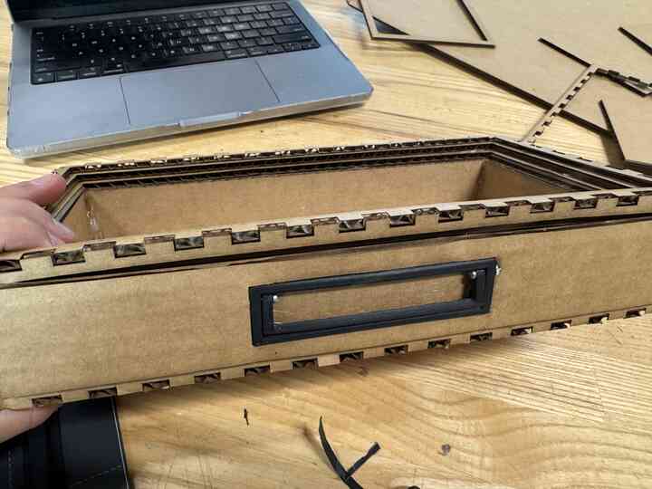
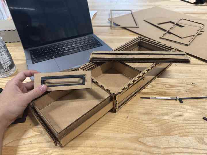
I modelled a side, front, and top face that would be able to slide in and out of the box.
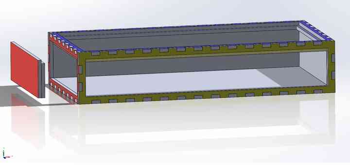
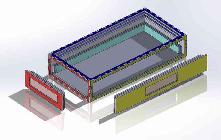
Then I modelled a drawer that could slide into both the front and side faces.
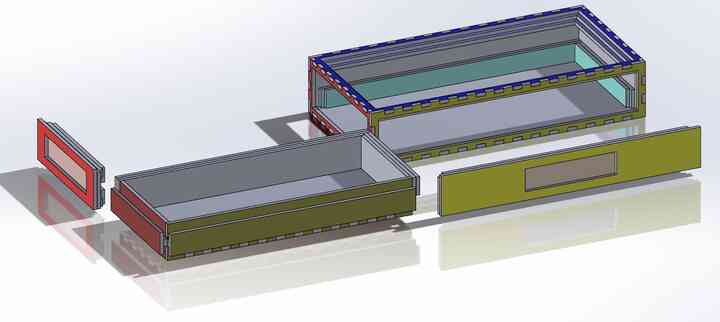
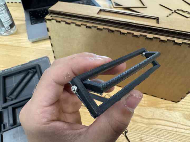
After that I modelled handles to go on each of the faces that could be 3D printed.
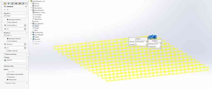
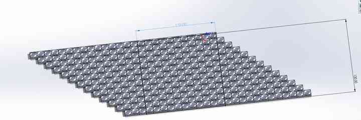
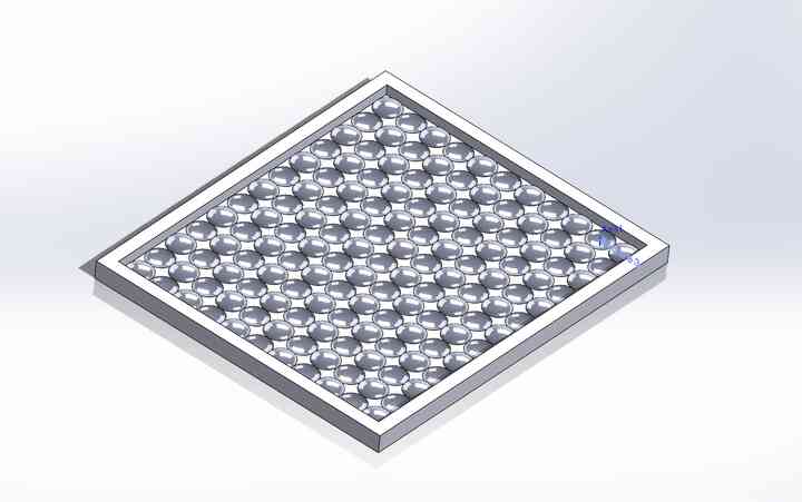
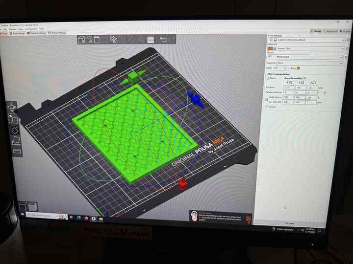
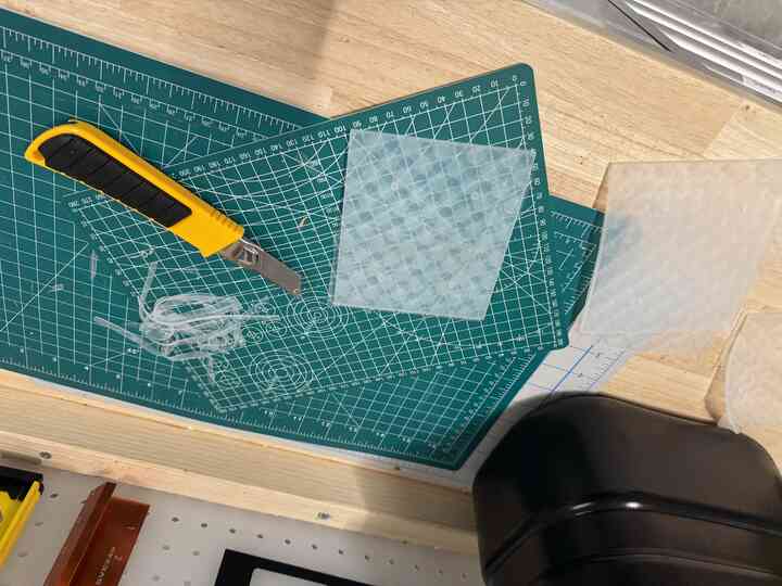
At this point I realized I could CAST the mat for the toolbox to include that aspect in my final project. Before, it was just going to be a casted handle but I felt this made more sense since it was going to be a softer silicone.
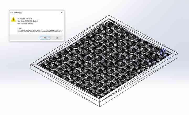
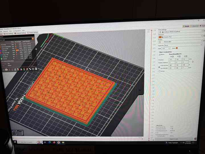
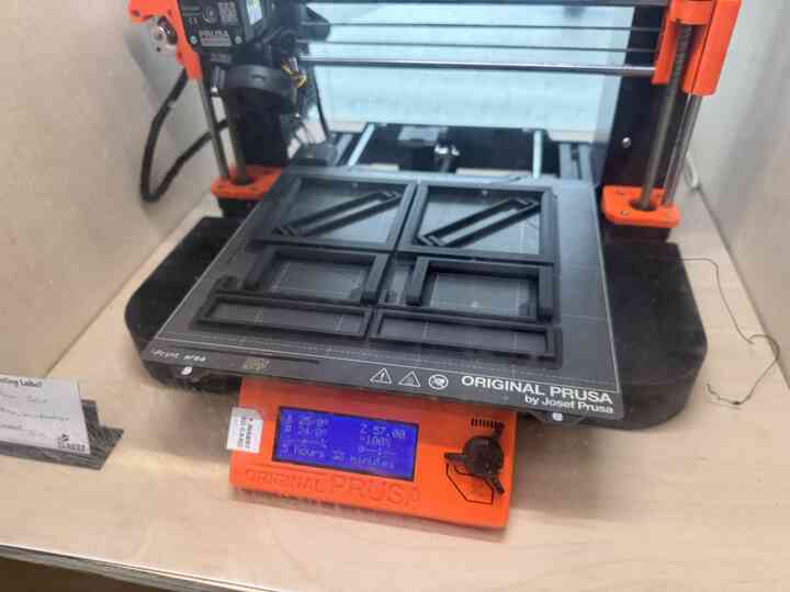
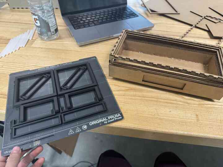
I modelled and 3D printed the mold for the mat on the Prusa MK4s in the Mechanical Engineering labs.
Printing!
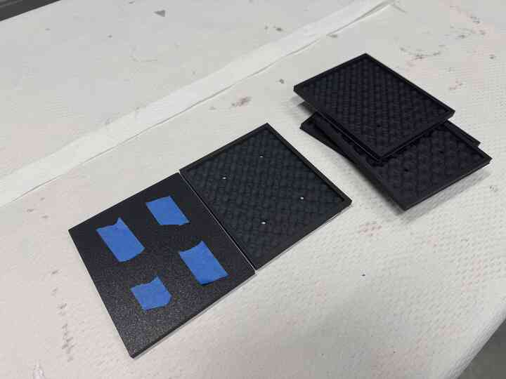
In the meantime I 3D printed the handles I modelled prior.
I got the mold out of the printers and sprayed them with mold spray at my colleague Hanna's recommendation, and got to work.

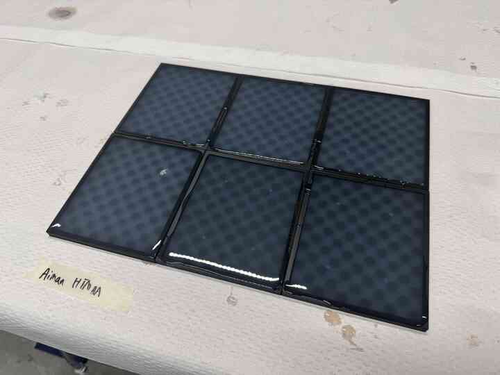
I used Ecoflex 50, which was a softer silicone I'd used before with a pretty long pot and curing time, basically taking a day.

Here are the molds, filled with the silicone.
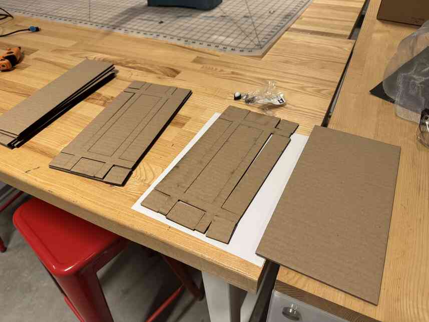
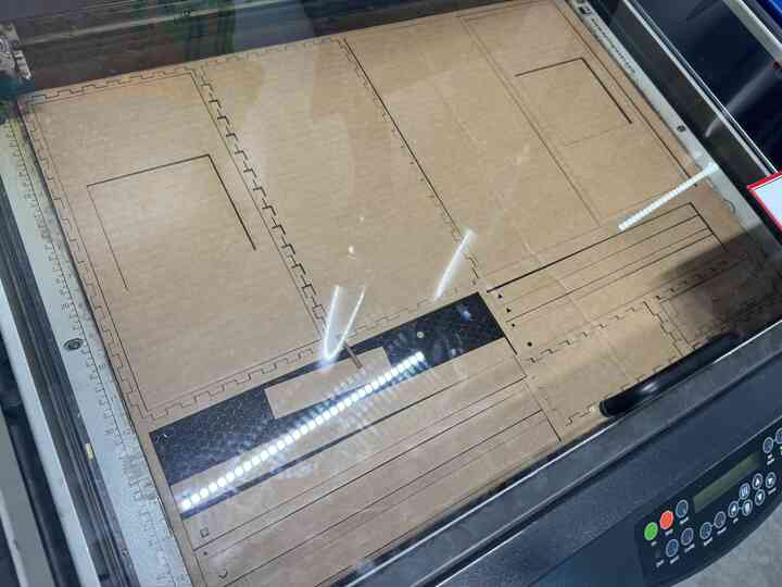
I took the carboard from the stock and cut it into manageable sizes on the large format cutter.

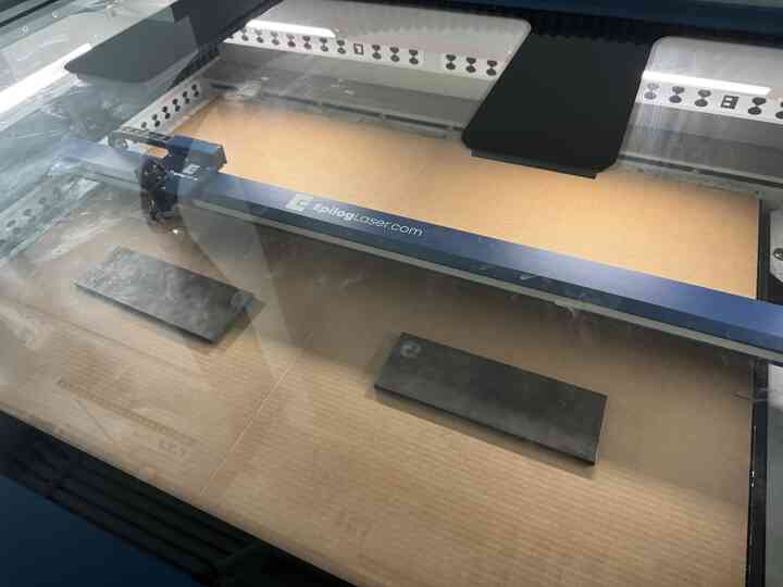
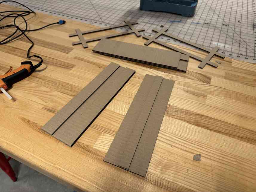
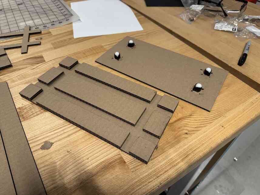
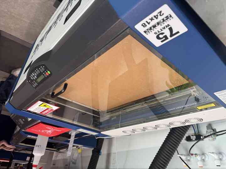
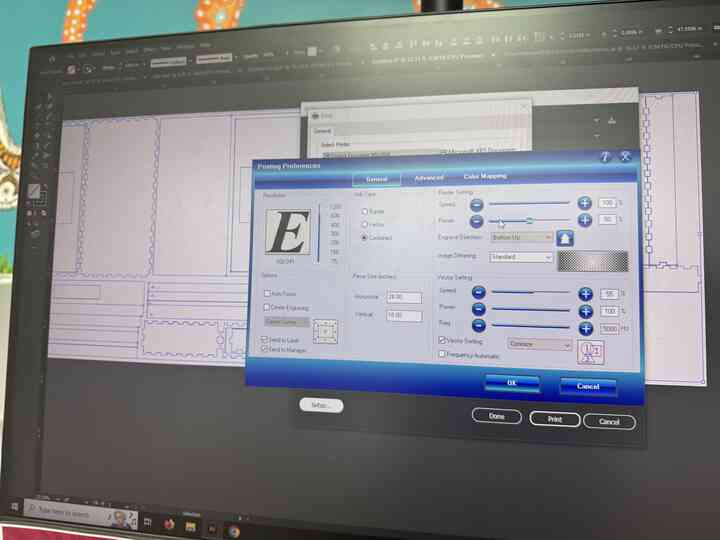
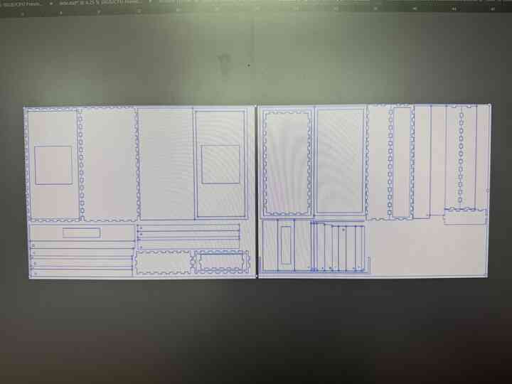
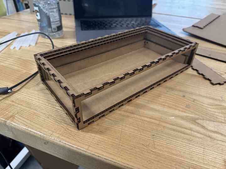
Then I laser cut the faces of the toolbox. I arranged all the faces that needed to be cut out in 3 24"x12" sheets because thats what I thought we had, but since I shifted to the class cardboard stock, I now had 24"x18" pieces, so I could rearrange them into 2 sheets of that.
It's beautiful!
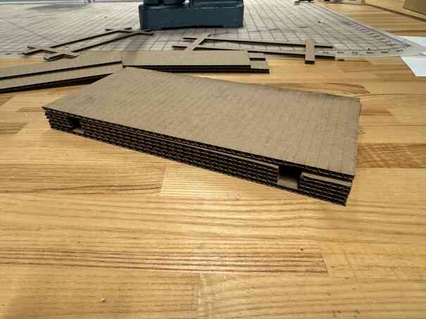
Following that, I assembled all the faces using hot glue.
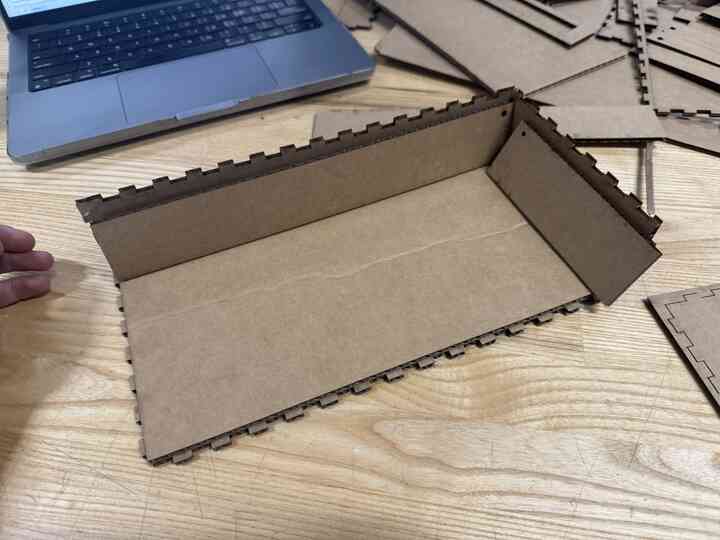
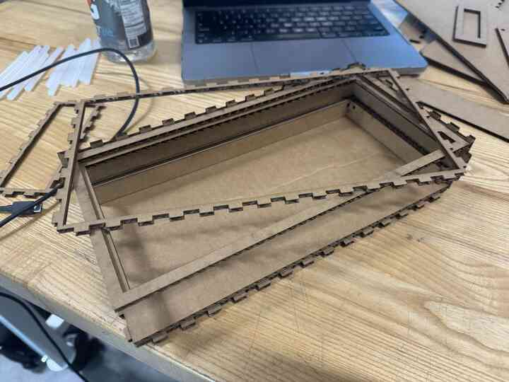
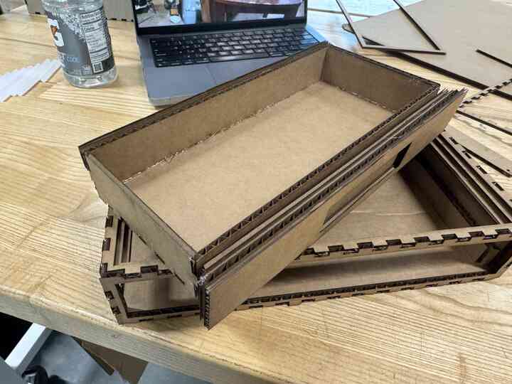
Here you can see how the sliding mechanism is meant to work.
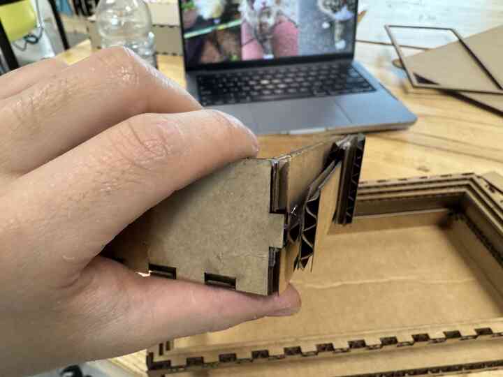
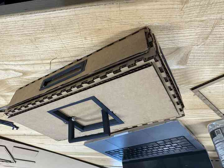
Next, I put on the handles by hot gluing them into place.
They swiveled on simple M2 hardware.
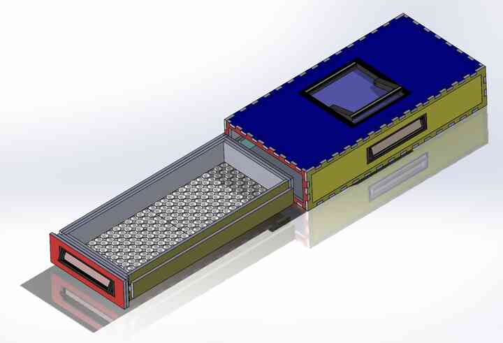
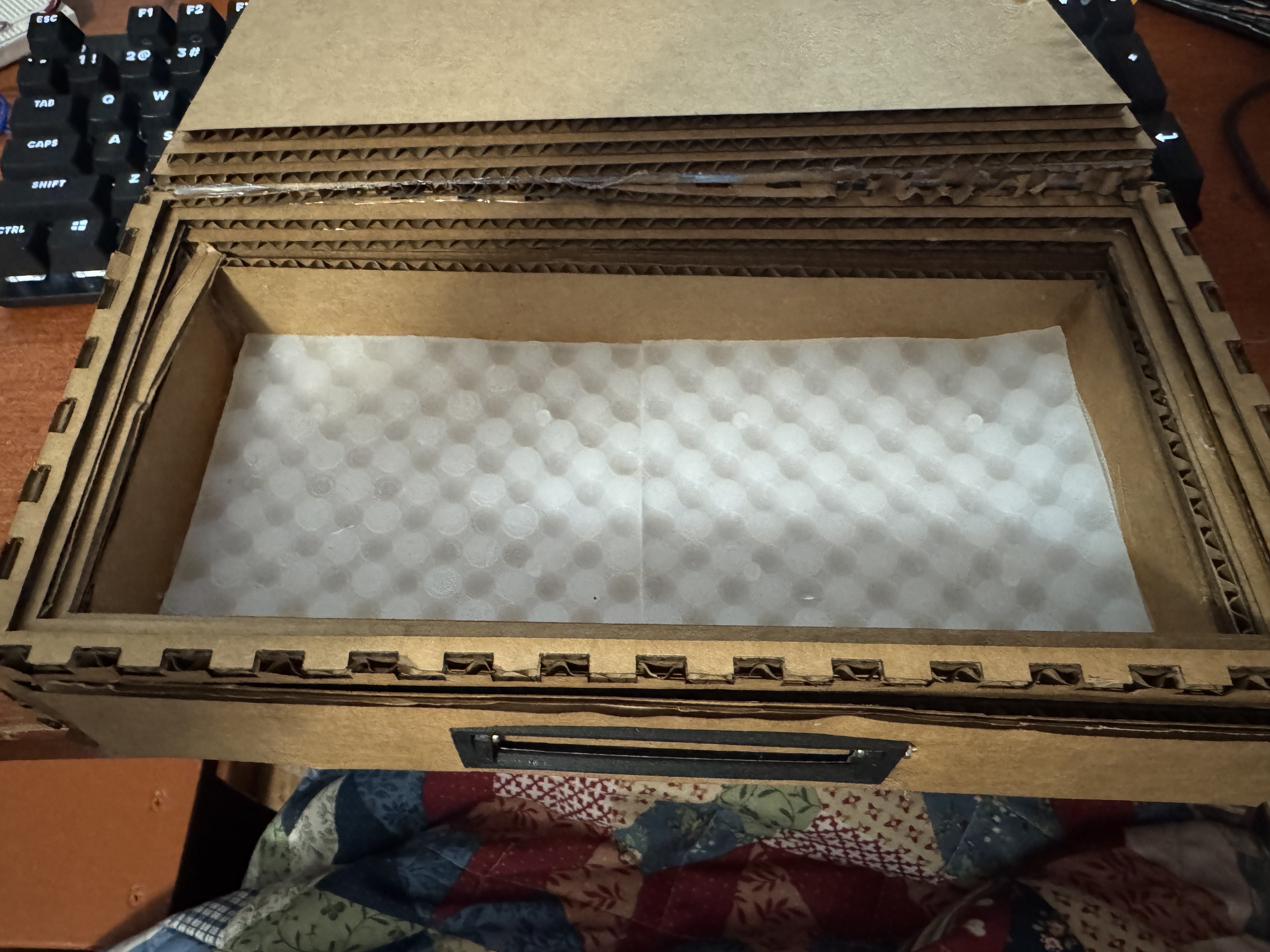
Look at this beautiful assembled toolbox!
I got the mat out of the mold and put it into the toolbox.
Anyway, onto the electronics, now!
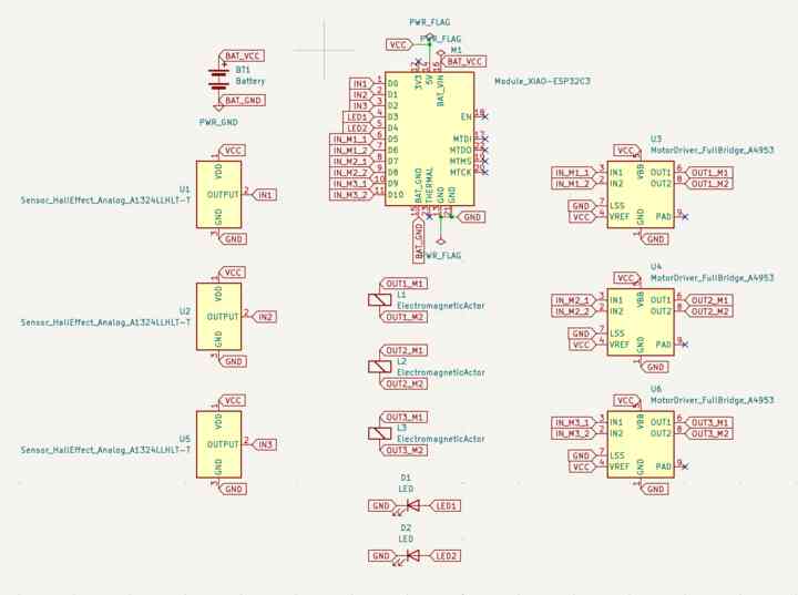
I designed a schematic that allowed the ESP32 to interface with three hall effect sensors, two indicator LEDs, and three electromagnets using three motor drivers.
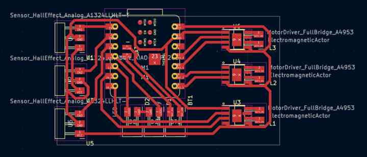
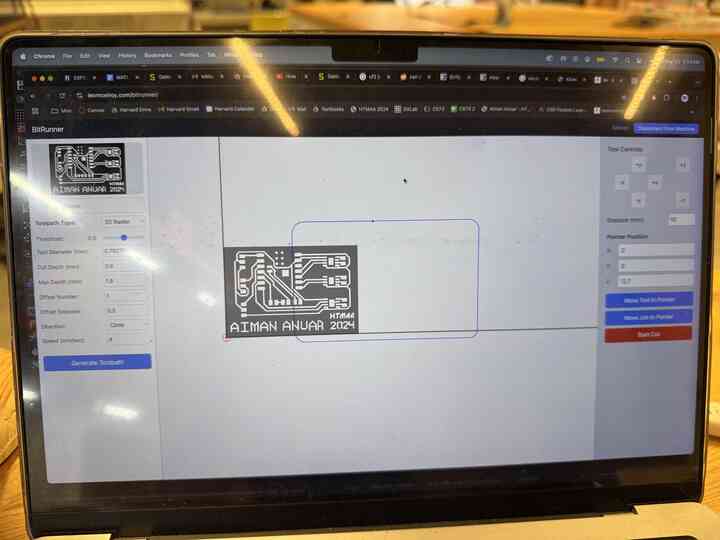
Here's what the PCB looked like!
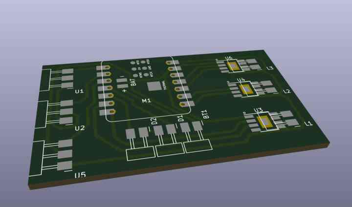
And here's a preview of the PCB when actually made.
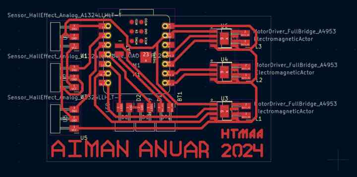
For fun I decided to add a calling card to the bottom of my PCB since I was really proud of all the trace work I did.
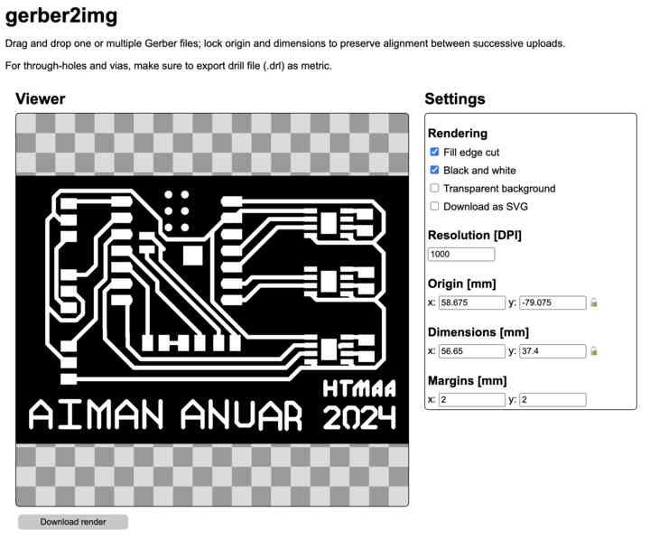
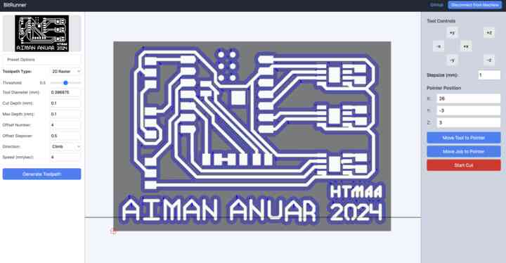
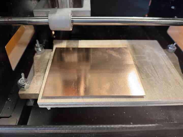
I put the files onto Bitrunner and started the job on the Roland!
LOOK AT MY BEAUTIFUL PCB! It's enough to make a grown man cry!
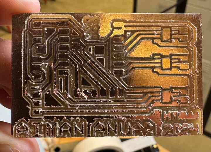
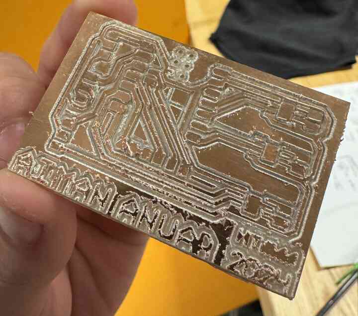
Sadly, if you look closely, one of the traces on the left side overlaps and shorts ground to power, so I could not proceed further. This is where my PCB work ends due to time constraints.
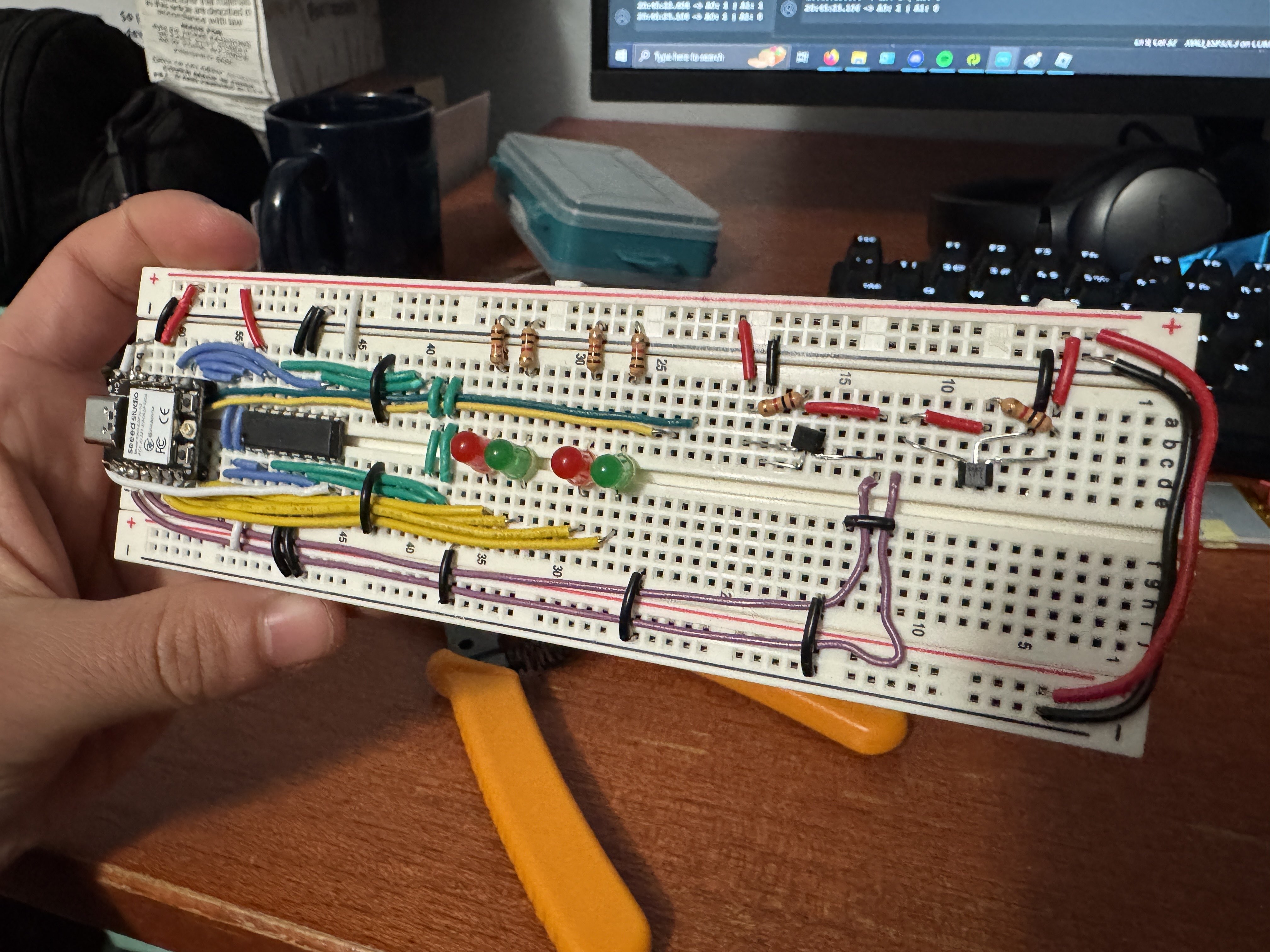
I was able to make a little progress on the software component.
Here is a video that demonstrates the use of the electromagnet that would lock two side by side drawers together.
Here is a video that demonstrates the use of the hall effect sensors to detect nearby drawers. At first it didn't work.
I looked up the problem and found out that I needed to add a resistor from 5V to Output to pull the hall effect sensor back to 5V. Otherwise, it would trigger but not untrigger..
Due to time constraints, that's all I was able to do software-wise.
Conclusion
I did not have enough time at all to finish my project, and had to continue working on it past the project presentation time, which I hope to improve in the future. I've learned to implement spiral development over the course of this semester and I think that's one of my greatest takeaways from this class is time management. In this project I implemented techniques from many weeks of class— 3D CAD, laser cut cardboard, 3D printed handles and molds, casted silicone mats, electronically simulated, designed, and produced PCBs that have hall effect sensor inputs and electromagnet outputs, and microcontrollers that are supposed to interface with each other and communicate with a phone wirelessly. Although I didn't use CNCíng, machine building, or my wildcard, I feel that my project is multifaceted enough to reflect what I learned in this class. In the future I would like to start my project way earlier and also improve on my design by manufacturing it out of wood, and incorporating the electronics INTO the mechanical toolbox, something I was previously unable to do due to time constraints, but with enough time, I feel like I could find a way to satisfactorily package all of the wiring and componentry into the toolbox. Anyway, that's all for now. I want to give a huge thanks to Neil for everything he has taught me and for his class, to my TAs, Leo and Gail, for all their incredible help and support, and to my friends in the Harvard section, who without them, I would not survive this class.
Check out some other relevant information at the final project breakdown!
Mechanical Component File Download Electrical Component File Download Electrical Component File Download
Home