HTMAA 2024 - Week 9
Output Devices
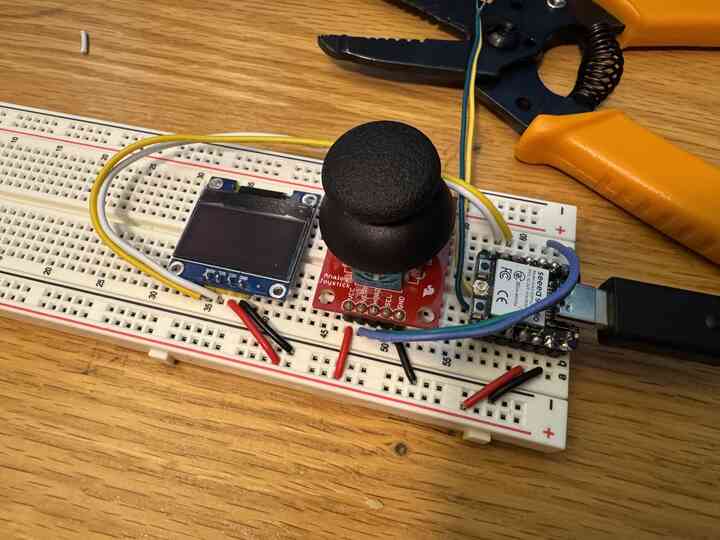
HomeContinuing on from my Simon Says game last week, I decided to add a monitor to it to display the status of the game on an LCD screen instead of the computer monitor.
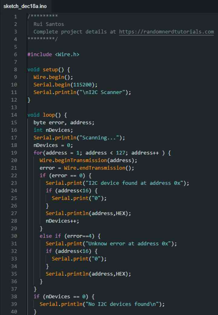
I took code from and followed this tutorial to get the screen initialized.
At first it didn't work.
To debug, I tried scanning for if the device was actually being detected.
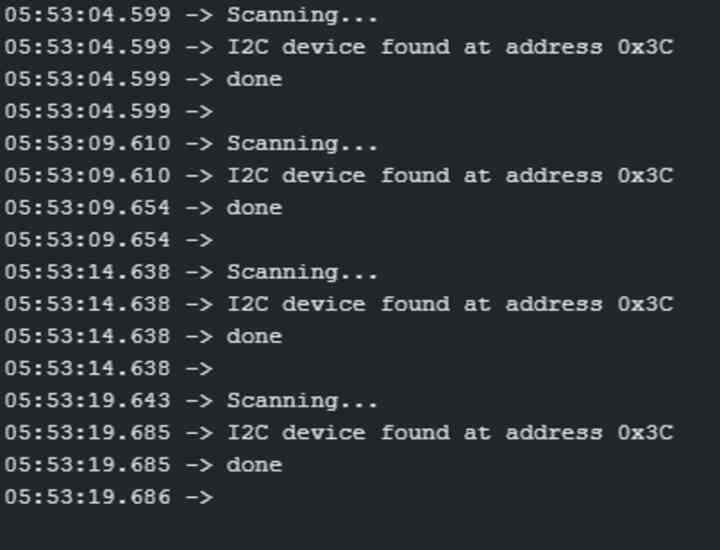
At that point, I realized that the display itself was broken and swapped it for another, working screen.
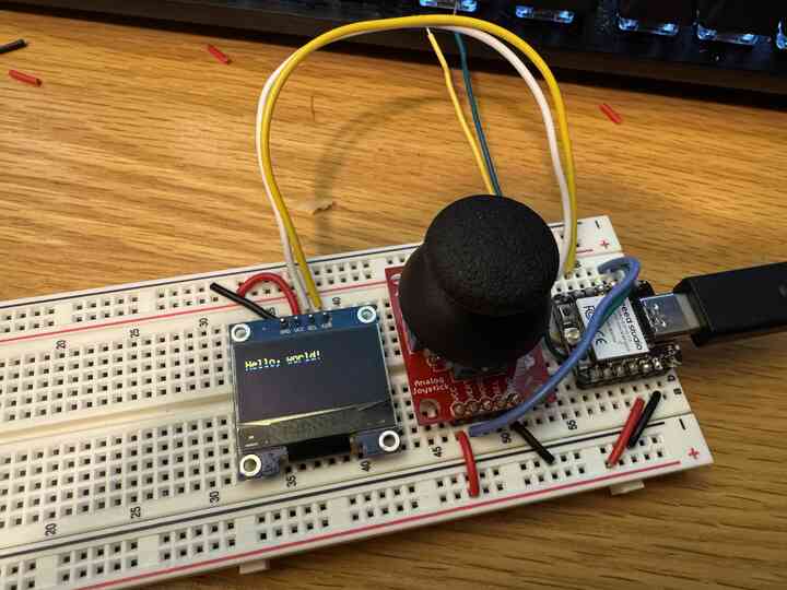
Huzzah, it worked!
So I played around with the template code, and at first I thought this was the proper way to send text to the display.
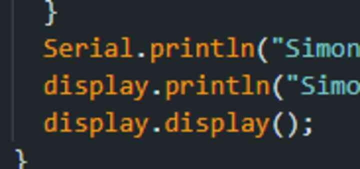
But it turns out, you have to restart the cursor position every time you send new text to the display, after clearing the screen.
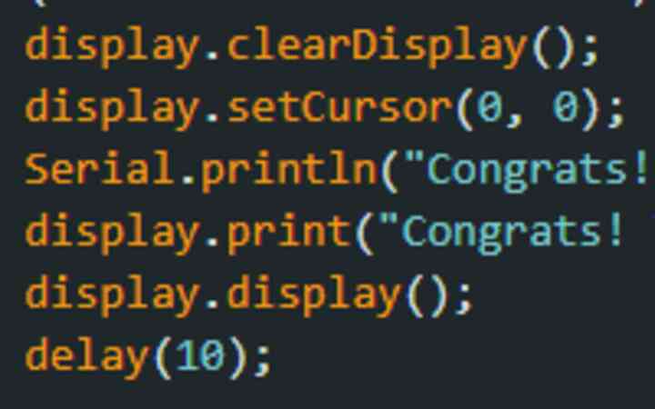
So THAT was actually the issue! When I put the old screen back it booted up just fine!
Anyway with that out of the way, I modified the code to work with my Simon Says code and from there it was history!
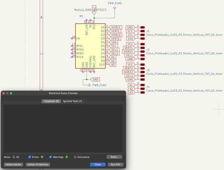
I took this working breadboard and made it into a schematic on KiCad.
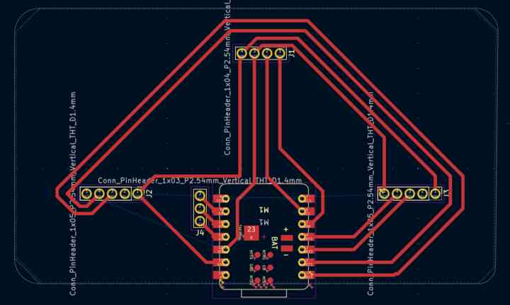
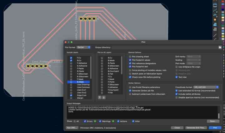
Here is the PCB diagram. Note that I tried to make it have rounded corners.
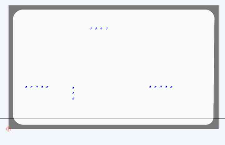
I exported out the gbr files. Because there were through holes (vias) I also exported drill files.
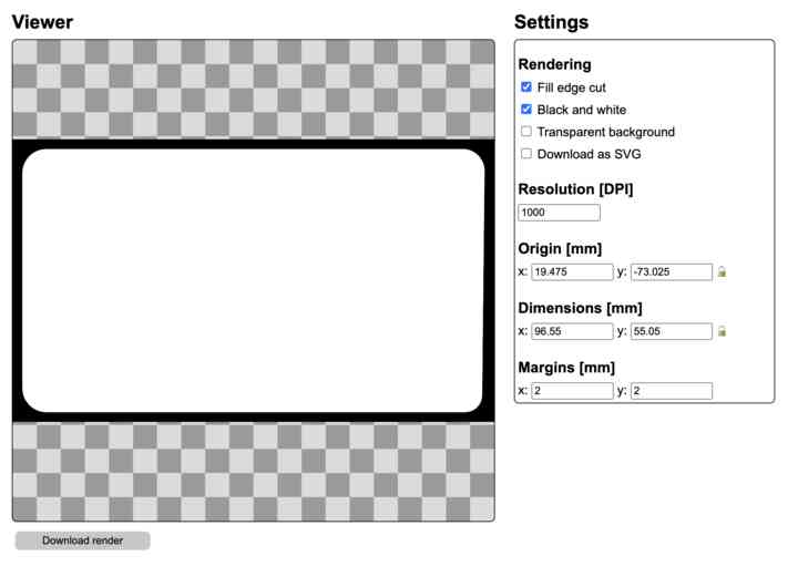
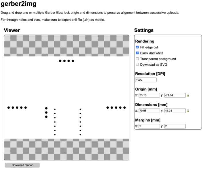
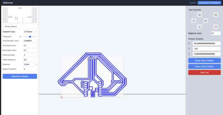
Putting it into gerber2img, I got out 3 files for contouring, edge cuts, and the drilling.
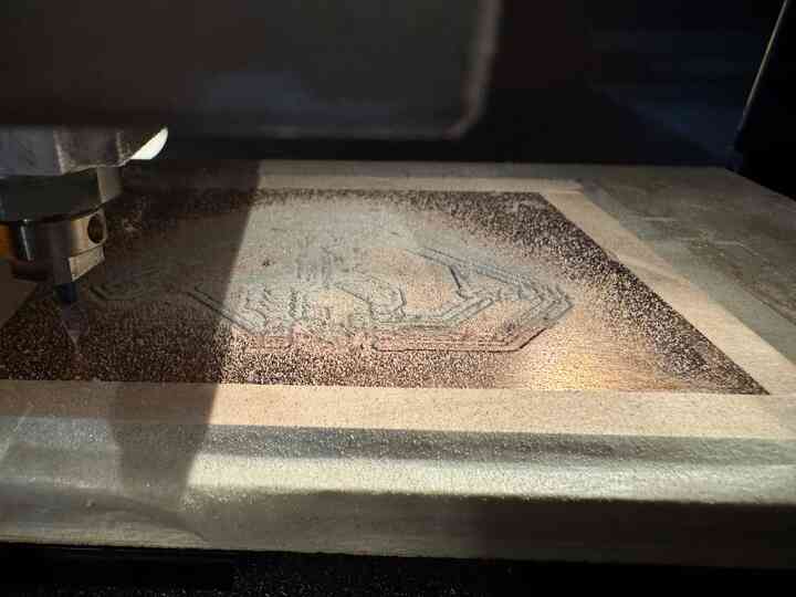
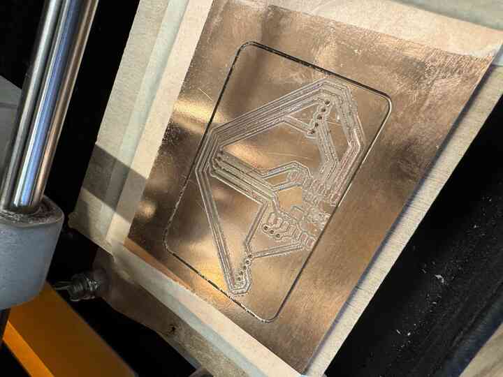
I then put it into bitrunner and initialized the cut.
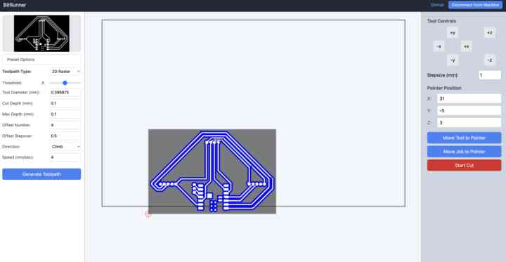
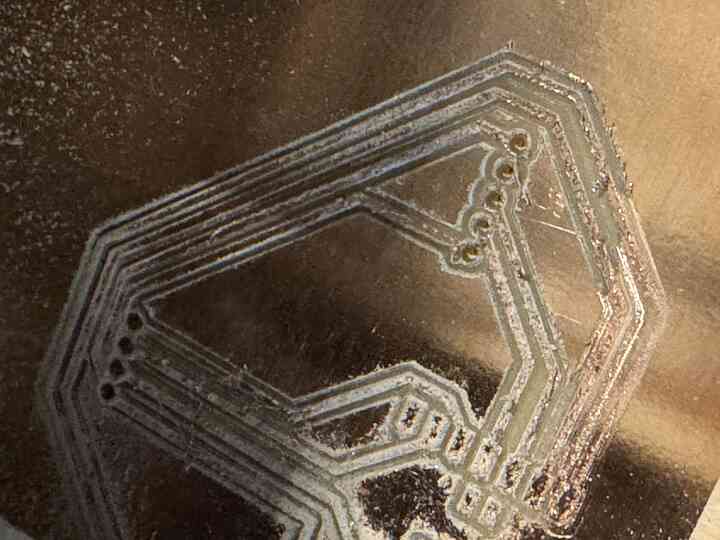
It looked great as it was milling, although some tiny little hairs came out..
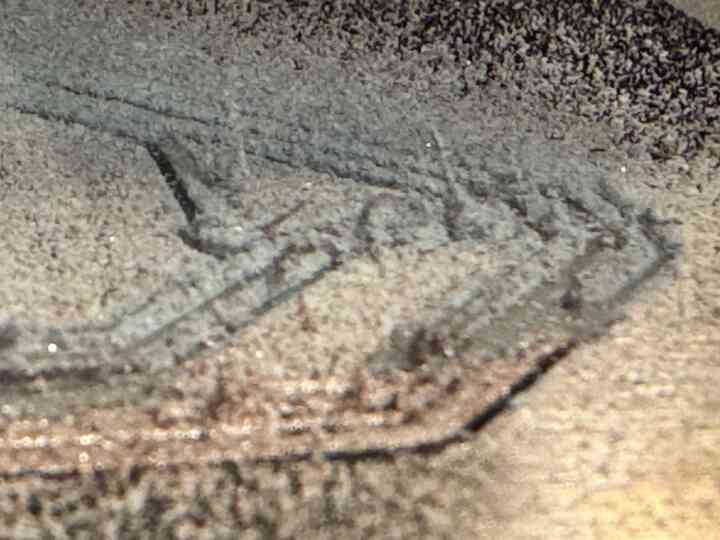
The drill file was not the same size as the original file so I had to manually align it.
The vias came out well for everything EXCEPT for the pins of the microcontroller.
I realized I'd have an issue soldering the joystick because it was already soldered to its header pins and the milled PCB lacked through holes, so I just soldered the base of the headers to the PCB.
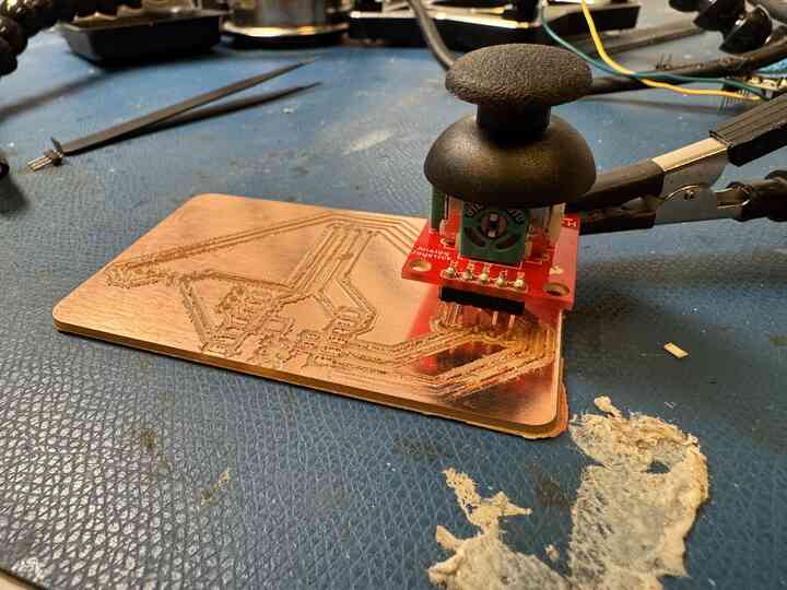
This approach, however, would not work on the screen, so I eventually decided to just put female headers on that the pins of the screen and the ESP32 could plug into.
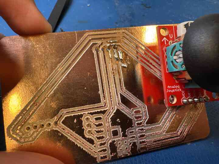
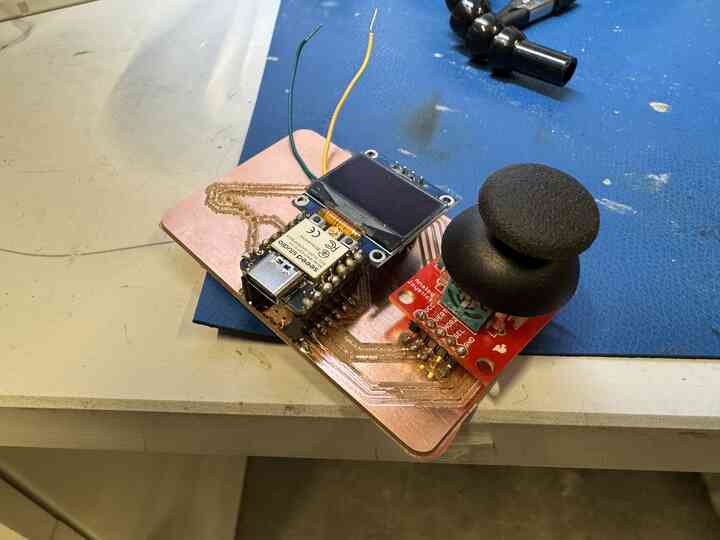
Here's the final board! I forgot to take a video of it working but it worked out pretty well! There is a slot for a second joystick in case I wanted to add one but I figured with the soldering pain already happening to leave it alone.
That's it for output week! I'm glad I was able to integrate both inputs and outputs into this board, and get some practice with using them. In the future, I think my outputs for the toolbox will simply just be indicator LEDs since I don't need any complicated analog detection mechanisms, only digital detection. But if I can do analog, then digital inputs and outputs will be no problem at all!
Home