Communication and Networking
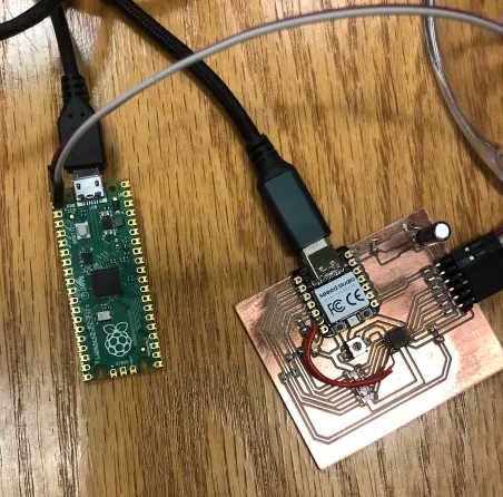
For this week, I decided to work on a part of my final project. I wanted to wire communicate between a Pico (my main board) and the stepper motor board from Week 9.
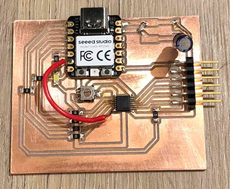
Luckily for current me, past me had already made a port to the TX and RX lines. I was still designing the final board, so I decided to just connect directly to a Pi Pico Board running Micropython, as I wanted to have the Pico board do API calls and Micropython was easier to do it in. I first tested out UART with MPython on a test Pi Pico and a test Xiao.
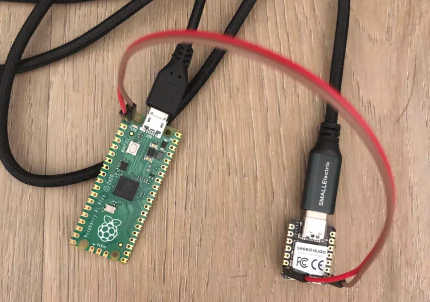
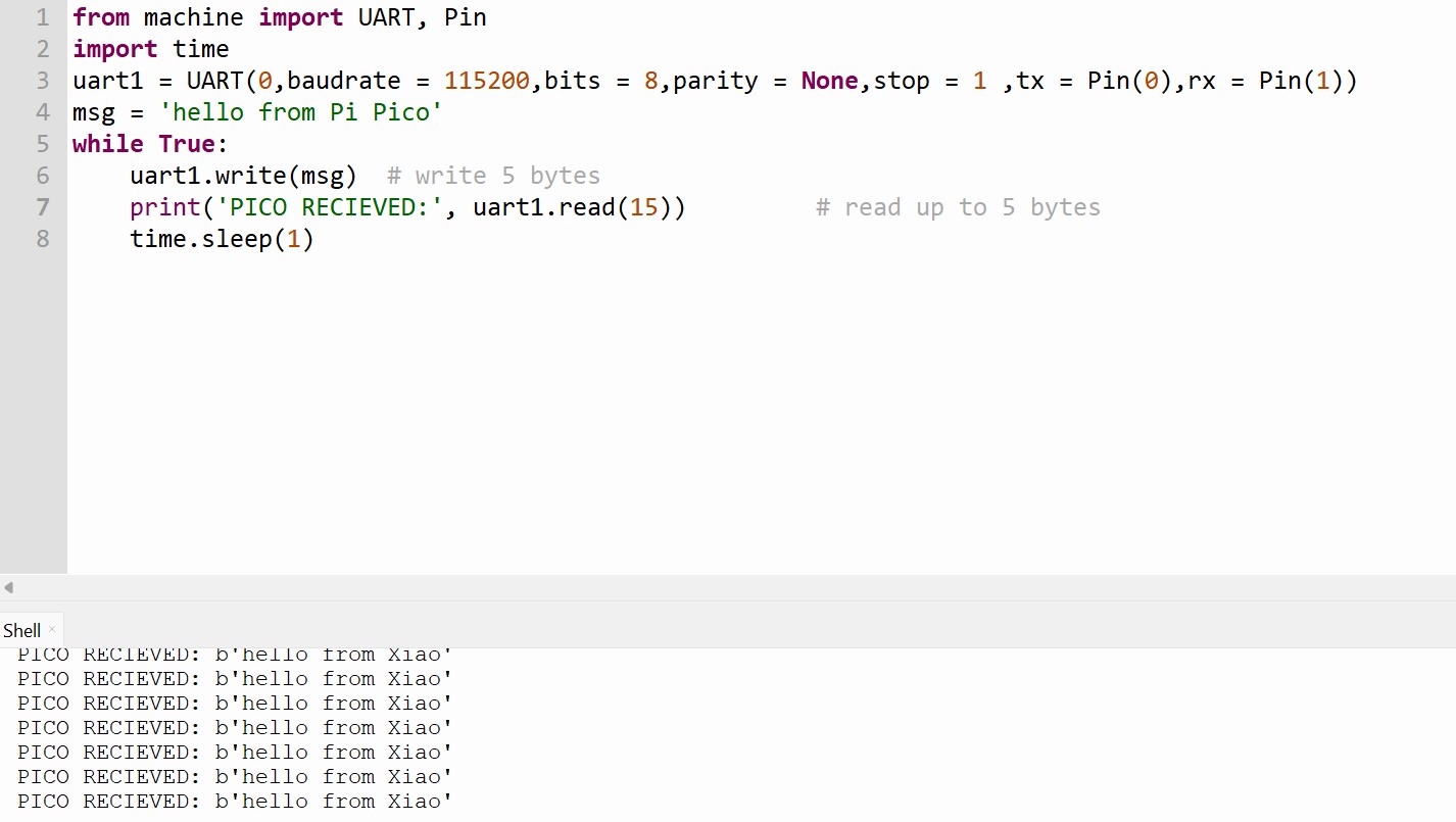
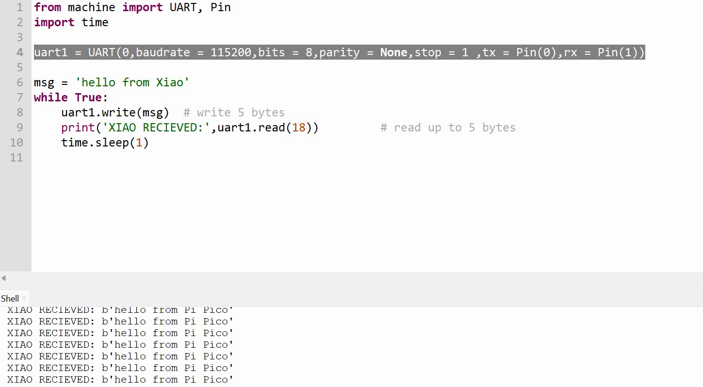
For the actual board, I wanted the Pico to control the speed of the stepper motor by cycling through some numbers.
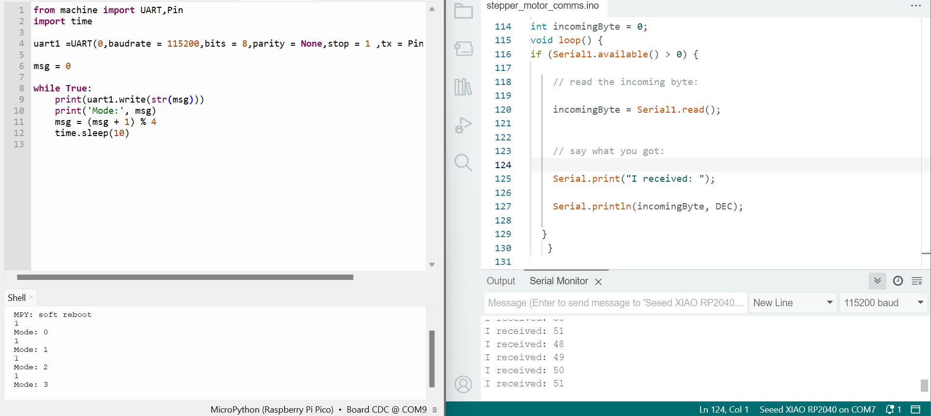
However, when I moved to use the motor of the stepper motor board, I ran into an issue where my computer would shut down when I plugged the stepper motor board in. This didn't happen in week 9, and after talking to Anthony, I found out that if the stepper motor is idle, it draws a ton of current. So I changed the potentiometer to what I thought was the highest resistance, and tried to continue. Then it shut down again, and I learned that I had done the opposite of what I intended, as I was measuring resistance from VREF to GND and maximizing that.
I reversed the direction I was spinning so it works, but I couldn't have maximum resistance as the motor wouldn't turn in that case.
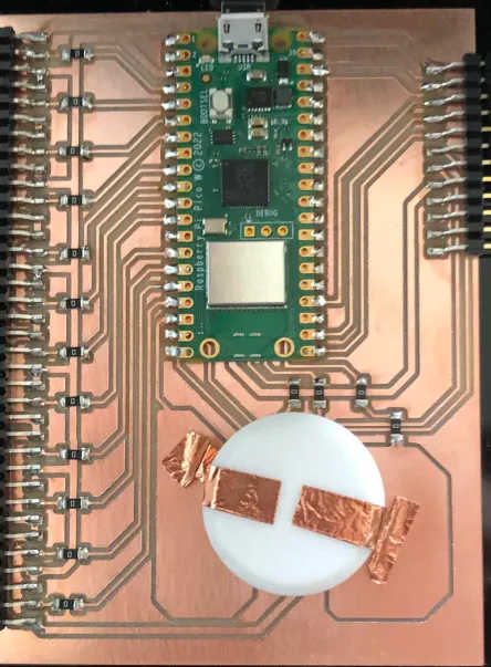
For my final project, I wanted to connect to the DSN API. The Pi Pico W has built in wifi capabilities, so I decided to use it.
For connecting to the DSN API, I knew of a friend who had done something similar. Adapting to Micropython with its own request module, I was able to save down a text of the request onto the Pico, as Micropython has a tendency to run out of program memory.
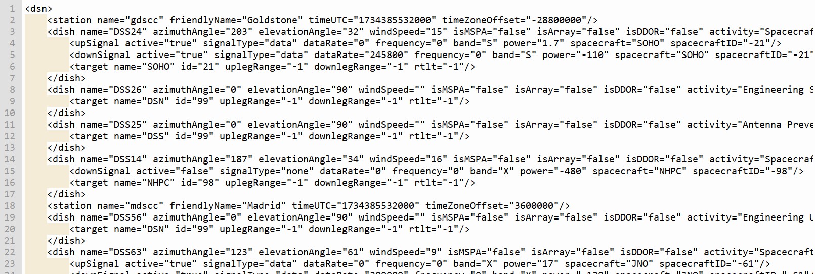
However, since Micropython doesn't have a good xml parser, I had to write my own. Fortunately there were only a couple of things I needed from the request, so I only needed to pull out the dish name, spacecraft, and uplink or downlinking.

I was able to get the uplinking and downlinking spacecraft mapped to the antenna.

Code
import network
import requests
import xmltok

def connect():
    ssid = 'REPLACE'
    password ='REPLACE'
    # Connect to network
    wlan = network.WLAN(network.STA_IF)
    wlan.active(True)

    # Connect to your network
    wlan.connect(ssid, password)
    print('connected!')

connect()

def poll_dsn():
    dish_activity = dict()
    active_spacecraft = set()
    current_response = requests.get('https://eyes.nasa.gov/dsn/data/dsn.xml')
    response_content = current_response.content.decode("utf-8")

    with open('dsn_poll.txt', 'w') as file: # Write the string to the file file.write(data)
        file.write(response_content)

    with open('dsn_poll.txt', 'r') as file: # Write the string to the file file.write(data)
        token = xmltok.tokenize(file)
        send_space = False
        current_dish = 'N/A'
        activities = []
        for i in token:
            # print(i)
            if i[0] == 'START_TAG' and i[1][1] == 'dish':
                current_dish = next(token)[2]
                # print(current_dish)
                current_line = current_dish
                for _ in range(7):
                    current_line = next(token)
                # print(current_line)
                if current_line[2] in['Spacecraft: TTC', 'Spacecraft Telemetry, Tracking, and Command']:
                    # print('found activity')
                    send_space = True
            if send_space:
                if i[0] == 'START_TAG' and i[1][1] in ('upSignal', 'downSignal'):
                    signal_name = i[1][1]
                    current_line = i
                    # print(current_line)
                    current_line = next(token)
                    if current_line[2] == 'true':
                        for _ in range(6):
                            current_line = next(token)
                        activities.append((signal_name, current_line[2].lower()))
                        active_spacecraft.add(current_line[2].lower())
            if i[0] == 'END_TAG' and i[1][1] == 'dish':
                dish_activity[current_dish] = activities
                activities = []
                current_dish = 'N/A'
                send_space = False
    return dish_activity, active_spacecraft

print(poll_dsn())
Resources
Part 1 Pico Code (requires micropython installation)
from machine import UART,Pin
import time

uart1 =UART(0,baudrate = 115200,bits = 8,parity = None,stop = 1 ,tx = Pin(0),rx = Pin(1))

msg = 0

while True:
	print(uart1.write(str(msg)))
	print('Mode:', msg)
	msg = (msg + 1) % 4
	time.sleep(5)
Xiao Code
									//
// hello.DRV8428-D11C.ino
//
// DRV8428-D11C stepper hello-world
//
// Neil Gershenfeld 5/30/21
//
// This work may be reproduced, modified, distributed,
// performed, and displayed for any purpose, but must
// acknowledge this project. Copyright is retained and
// must be preserved. The work is provided as is; no
// warranty is provided, and users accept all liability.
//

#define LEDA D4
// #define LEDC 2
#define EN D5
#define DIR D0
#define STEP D1
#define M1 D3
#define M0 D2
#define RX D7
#define NSTEPS 1000
#define DELAYHIGH 1000
#define DELAYLOW 1000
#define BLINK 100

void setup() {
   pinMode(LEDA,OUTPUT);
   pinMode(EN,OUTPUT);
   pinMode(STEP,OUTPUT);
   pinMode(DIR,OUTPUT);
   digitalWrite(LEDA,LOW);

   digitalWrite(EN,LOW);

   digitalWrite(STEP,LOW);

   digitalWrite(DIR,LOW);
   Serial.begin(115200);
   Serial1.begin(115200);

   }

void blink_off() {
   digitalWrite(LEDA,LOW);
   delay(BLINK);
   digitalWrite(LEDA,HIGH);
   }

void do_steps() {
   digitalWrite(DIR,HIGH);
   for (int i = 0; i < NSTEPS; ++i) {
      digitalWrite(STEP,HIGH);
      delayMicroseconds(DELAYHIGH);
      digitalWrite(STEP,LOW);
      delayMicroseconds(DELAYLOW);
      }
   }

void step_2() {
   digitalWrite(M0,HIGH);
   digitalWrite(M1,LOW);
   pinMode(M0,OUTPUT);
   pinMode(M1,OUTPUT);
   }

void step_4() {
   digitalWrite(M0,LOW);
   digitalWrite(M1,HIGH);
   pinMode(M0,OUTPUT);
   pinMode(M1,OUTPUT);
   }

void step_8() {
   digitalWrite(M0,HIGH);
   digitalWrite(M1,HIGH);
   pinMode(M0,OUTPUT);
   pinMode(M1,OUTPUT);
   }

void step_16() {
   digitalWrite(M1,HIGH);
   pinMode(M0,INPUT);
   pinMode(M1,OUTPUT);
   }

void step_32() {
   digitalWrite(M0,LOW);
   pinMode(M0,OUTPUT);
   pinMode(M1,INPUT);
   }

void step_128() {
   pinMode(M0,INPUT);
   pinMode(M1,INPUT);
   }

void step_256() {
   digitalWrite(M0,HIGH);
   pinMode(M0,OUTPUT);
   pinMode(M1,INPUT);
   }

int incomingByte = 0;
void loop() {
if (Serial1.available() > 0) {
    blink_off();
    // read the incoming byte:
    incomingByte = Serial1.read() - 48;
    // say what you got:
    Serial.print("I received: ");
    Serial.println(incomingByte, DEC);
    switch (incomingByte){
      case 0:
        step_256();
        break;
      case 1:
        step_128();
        break;
      case 2:
        step_32();
        break;
      case 3:
        step_16();
        break;
    }
  }
    digitalWrite(EN,HIGH);
    do_steps();
    digitalWrite(EN,LOW);
   digitalWrite(LEDA,LOW);

   }
Group Project