
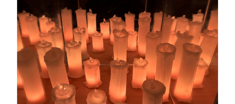
candles with optional mirror hat

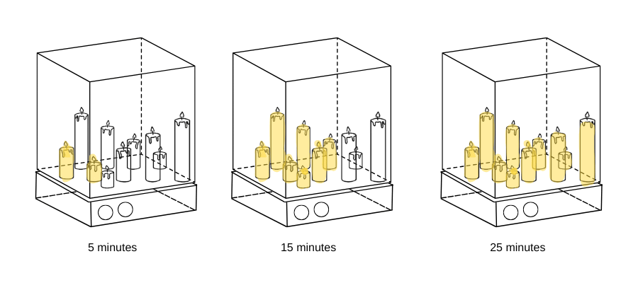
the lumitempo pomodoro timer uses 10-15 casted candle-like led lights, which gradually illuminate over a 25-minute timer to provide a calming study aid. the design incorporates embedded programming, laser cutting, 3d printing, molding and casting, and touch sensors. during the break period, the leds perform a wave animation, adding a soothing visual effect.
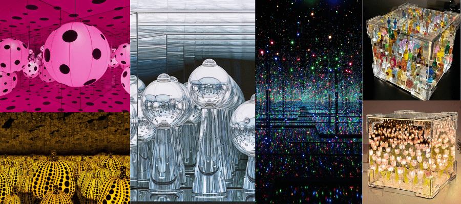
i use this pomodoro timer practically every day, so making a sort of machine out of it seemed to be a cool idea. i wanted to think about what forms i could use, so i started looking at lamps in art and design online. i found an infinity box-style tulip lamp and thought it would be cool to make my own version of it. i wanted to keep the mirror box form, but i had to give more thought about what to fill it with. i looked at some art from yayoi kusama and josiah mcelheny and went “wow that’s cool” but couldn’t find any direct inspo. i decided on making little candles to fill up the box.
i looked at the htmaa website, and found some awesome pomodoro timers. i actually think my project is closer to an hourglass than a true pomodoro timer. i guess i was interested in telling time in a less precise/more visual way. i like the idea that we don't know exactly how much time has passed but we know we're getting closer
electronics
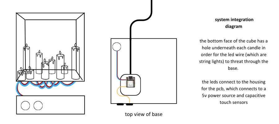
housing
the cost (to me) was roughly $15 for the LEDs. combining the cost of the xiao, the wood, the sensors, and the wax, we could estimate the total cost at roughly $25.

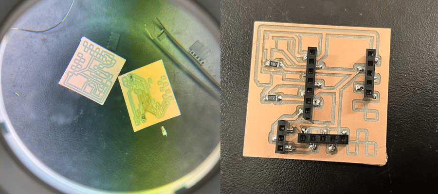
the electronics are relatively simple, involving two sensors and one output. I designed one pcb in order to bridge the two of these functions. Below is an overview of how I designed the pcb. Please see my the electronics design week for more detailed information.
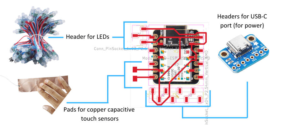
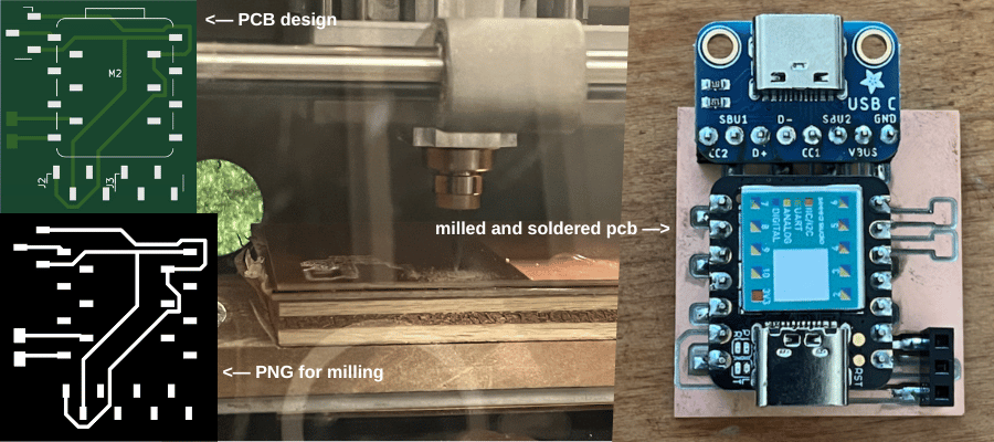
after designing the pcb, i milled it using the roland machine at the reef. with the help of leo, i got it soldered!
after receiving feedback from the group review in class, i realized that i couldn’t connect the external power and the xiao at the same time. yet, i still had to use external power for the leds because my laptop couldn’t provide enough amps. i know that the pcb would be fine for when the light box is just running—but while testing and programming i need to simultaneously run the xiao and external power so that i could see how to the leds update.
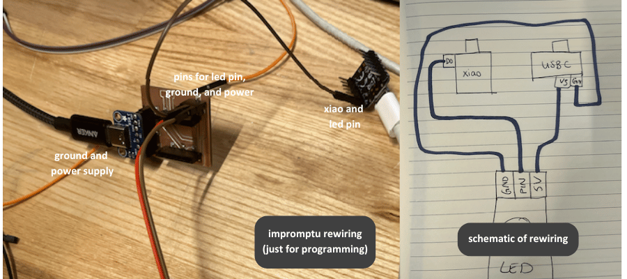
leo and i fiddled with the set up until we could turn on the leds. we ended up wiring the leds’ ground and power pins to the usb-c breakout, and the data pin to the xiao. then, we connected the xiao to my laptop. i used code from electronic outputs week to test the set up, and it worked! the only difference was that the rgb/grb distinction was switched with these leds, so the colors were warped. that being said, it seemed to function alright.
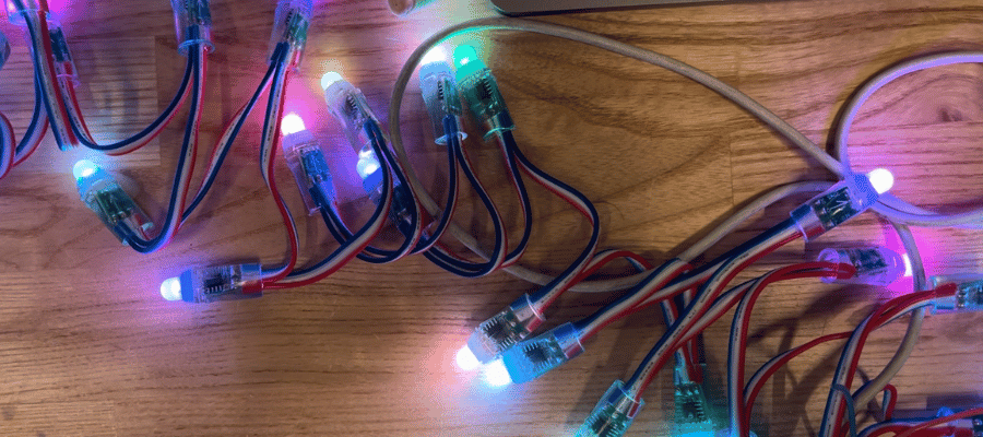
to program the leds, i needed one phase where the leds illuminated slowly, one by one and one phase where the leds had pattern for a break. i wanted to get to work programming, so i ran test code through my programming set up. my test code looked crazy on the leds. i couldn’t so much as get the leds to light up one color or turn off using code.
below is a video where the leds were set to light up to red:
to debug, i tried any and everything:
every time one didn’t work, i told myself “i bet the wiring’s off” but i never bothered to check the wiring. eventually, i decided to take my pcb and remove the piece of copper that connected 5v to the xiao. that way, when using the pcb and the external power supply, it wouldn’t short the xiao. and voila! success.
upon retrospect it seems a bit obvious that i needed to connect the led’s ground pin to the xiao’s ground pin.
with a working led, i workshopped colors for my candle, then simply took example code from the adafruit neopixel library and tailored it for my project. luckily, most of the examples use time to control the leds, which is exactly what i want to do. for example, to illuminate one candle at a time, i took the “simple” example (which illuminates one led at a time until the whole strip is illuminated) and changed the delay between pixels illuminating from 500ms to 50,000ms (or 50 seconds). then, i workshopped the break phase. i decided to use a simple color-wipe.
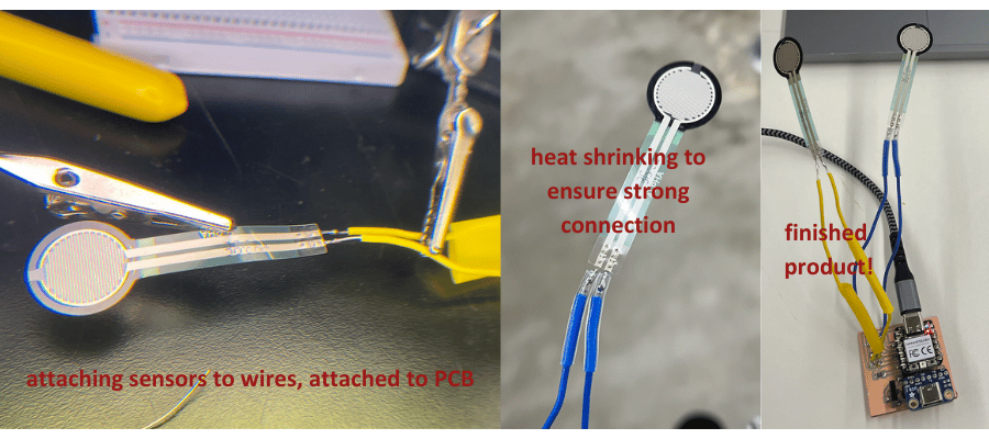
at gail's suggestion (and with the help of her pulling inventory), i switched from copper capacitive touch pads to adafruit force sensors. in order to connect the sensors to the lights, i needed to make a new pcb, because the one i used for the lights was incompatible with the sensors (and likely wouldn't have worked for copper touch sensors either tbh).
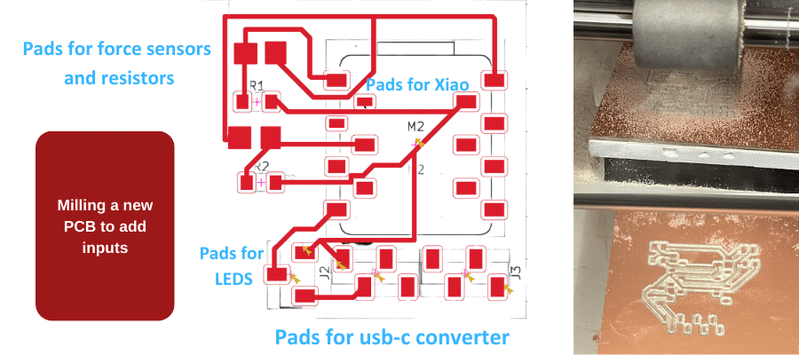
the new pcb accounted for the wiring issue i ran into with the LEDs when i was working on the outputs. i breadboarded the components separately, so i knew how to configure the sensors with the resistors (which i had never worked with before).
it was really difficult to solder the resistors, but it got done! the sensors were highly sensitive (made of thin metal and mostly plastic), so soldering them was daunting but it worked out. i needed to attach a wire between the sensors and the pcb because i wasn't sure if the pcb would be placed condusively for the sensors, which needed to reach the edge of the base of the structure.
to ensure the sensors were reading, I tested it with simple code (see electronic inputs week).
after confirming both of the sensors were reading, i adapted my code for the outputs to work with the inputs. i don't have a strong coding background, so I worked very closely with chatgpt. that being said, the end product is really a mix of chatgpt's code and mine. i learned so much about debugging and what code says by iterating on my project. i ran into issues with the sensors being activated 15 times with one press, so I added debouncing. i ran into an issue of the sensor not controlling the entire LED strip, just the LED strip when it is in a certain animation phase, so I worked around that. i also ran into issues with the leds themselves (I almost shorted them by connecting ground to power and power to ground). the testing took quite a long time, but i ended up with this:
below is the full code i used. put simply, the blue sensor toggles the lights on and off. the yellow sensor toggles between two modes. one is a pomodoro timer that starts with a wash of color, then the lights light up individually until 25 minutes (in the demo it's much shorter), then there is a twinkle for a 5 minute break. the second mode is ambient mode, where the lights fade in and out at different saturations
  #include
    #include

    // Constants for NeoPixel
    #define PIN D6
    #define NUMPIXELS 12
    #define QUICK_DELAY 50
    #define SLOW_DELAY 120000
    #define TWINKLE_DELAY 100
    #define UNDULATE_DELAY 50
    #define TWINKLE_DURATION 300000

    Adafruit_NeoPixel pixels(NUMPIXELS, PIN, NEO_RGB + NEO_KHZ800);

    // Constants for Force Sensors
    int fsrPinD0 = D0;            // FSR connected to pin D0
    int fsrPinD3 = D3;            // FSR connected to pin D3
    int fsrReadingD0;             // Analog reading from the FSR D0
    int fsrReadingD3;             // Analog reading from the FSR D3
    int squeezeThreshold = 1000;   // Threshold for a "big squeeze"

    // Debounce variables
    unsigned long debounceTime = 1500; // 200 ms debounce delay
    unsigned long lastToggleTimeD0 = 0;
    unsigned long lastToggleTimeD3 = 0;

    // Animation states
    enum AnimationState { QUICK_WIPE_1, SLOW_WIPE, QUICK_WIPE_2, TWINKLE, AMBIENT_MODE };
    AnimationState animationState = QUICK_WIPE_1;

    // Variables to track state
    bool isLightsOn = true;       // Default state is ON
    unsigned long lastUpdate = 0;  // For non-blocking delays
    unsigned long twinkleStartTime = 0;
    int currentPixel = 0;

    // Ambient mode brightness control
    bool isAmbientMode = false;   // Track if ambient mode is active
    int ambientBrightness = 0;
    int ambientStep = 5;

    void setup() {
      Serial.begin(9600);
      pixels.begin(); // Initialize NeoPixel strip
      pixels.clear(); // Ensure all pixels are off at the start
      pixels.show();
      Serial.println("Setup complete. Lights ON.");
    }

    void loop() {
      unsigned long currentTime = millis();

      // Read FSR values
      fsrReadingD0 = analogRead(fsrPinD0); // Read the FSR on D0
      fsrReadingD3 = analogRead(fsrPinD3); // Read the FSR on D3

      // Check for a "big squeeze" on D0 (to toggle Pomodoro cycle)
      if (fsrReadingD0 > squeezeThreshold && (currentTime - lastToggleTimeD0 > debounceTime)) {
        isLightsOn = !isLightsOn; // Toggle the lights state
        lastToggleTimeD0 = currentTime; // Update debounce timer

        if (isLightsOn) {
          Serial.println("Turning lights ON...");
          animationState = QUICK_WIPE_1; // Reset animation state
          currentPixel = 0;
        } else {
          Serial.println("Turning lights OFF...");
          turnOffLights();
        }
      }

      // Check for a "big squeeze" on D3 (to toggle Ambient mode)
      if (fsrReadingD3 > squeezeThreshold && (currentTime - lastToggleTimeD3 > debounceTime)) {
        isAmbientMode = !isAmbientMode; // Toggle ambient mode
        lastToggleTimeD3 = currentTime; // Update debounce timer

        if (isAmbientMode) {
          Serial.println("Switching to ambient mode...");
          animationState = AMBIENT_MODE;
        } else {
          Serial.println("Switching back to Pomodoro cycle...");
          animationState = QUICK_WIPE_1;
        }
      }

      // If lights are on, handle animation
      if (isLightsOn) {
        updateAnimation();
      }

      delay(10); // Small delay to avoid overloading the loop
    }

    void updateAnimation() {
      unsigned long currentTime = millis();

      switch (animationState) {
        case QUICK_WIPE_1:
        case QUICK_WIPE_2:
          if (currentTime - lastUpdate >= QUICK_DELAY) {
            if (currentPixel < NUMPIXELS) {
              pixels.setPixelColor(currentPixel, pixels.Color(255, 80, 0)); // Orange color
              pixels.show();
              currentPixel++;
            } else if (currentPixel < NUMPIXELS * 2) {
              int secondPassPixel = currentPixel - NUMPIXELS;
              pixels.setPixelColor(secondPassPixel, 0);
              pixels.show();
              currentPixel++;
            } else {
              currentPixel = 0;
              animationState = (animationState == QUICK_WIPE_1) ? SLOW_WIPE : TWINKLE;
            }
            lastUpdate = currentTime;
          }
          break;

        case SLOW_WIPE:
          if (currentTime - lastUpdate >= SLOW_DELAY) {
            if (currentPixel < NUMPIXELS) {
              pixels.setPixelColor(currentPixel, pixels.Color(255, 80, 0));
              pixels.show();
              currentPixel++;
            } else {
              currentPixel = 0;
              animationState = QUICK_WIPE_2;
            }
            lastUpdate = currentTime;
          }
          break;

        case TWINKLE:
          if (currentTime - lastUpdate >= TWINKLE_DELAY) {
            if (twinkleStartTime == 0) {
              twinkleStartTime = currentTime;
            }

            if (currentTime - twinkleStartTime < TWINKLE_DURATION) {
              for (int i = 0; i < NUMPIXELS; i++) {
                if (random(10) > 7) { // Random chance to sparkle
                  pixels.setPixelColor(i, pixels.Color(255, 80, 0));
                } else {
                  pixels.setPixelColor(i, 0); // Turn off
                }
              }
              pixels.show();
            } else {
              // Reset for next cycle
              animationState = QUICK_WIPE_1;
              currentPixel = 0;
              twinkleStartTime = 0;
            }
            lastUpdate = currentTime;
          }
          break;

     case AMBIENT_MODE:
      if (currentTime - lastUpdate >= UNDULATE_DELAY) {
        ambientBrightness += ambientStep;
        if (ambientBrightness <= 0 || ambientBrightness >= 255) ambientStep *= -1;

        for (int i = 0; i < NUMPIXELS; i++) {
          pixels.setPixelColor(i, pixels.Color(ambientBrightness, 80 * ambientBrightness / 255, 0));
        }
        pixels.show();
        lastUpdate = currentTime;
      }
      break;

      }

    }

    void turnOffLights() {
      Serial.println("Executing turnOffLights...");
      pixels.clear();
      pixels.show();
    }
this project is fairly straightforward from an electronics perspective, but it was quite daunting to me. after struggling with malfunctioning LEDs and confused sensors, i was able to create a centralized pcb that integrates a xiao rp2040, LEDs, and two force sensors. with that done, the only thing left on the project is building the housing!

my original idea was to have one-way mirror housing so that the candles looked like they were going on forever. to do this, i lasercut clear acrylic into 5 6x6" squares, then applied one-way mirror according to the instructions. i was left with a murky, dark, not-so-reflective box when i assembled them. i looked at another mirror box i had lying around (from a non-HTMAA project), and found the reflectiveness quite nice. the only downside was that you couldn't see through these mirrors, but I thought that was a worthwile tradeoff for the reflectiveness
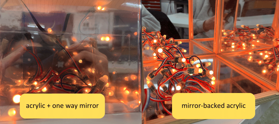
in the other project, the mirrors were adhered using hot glue to a wooden frame, so i took a heat gun to it to melt off the glue. after deciding to use the real mirrors (which were a manufactured mirror-backed acrylic), i cut them down to 6x6" squares and assembled them with superglue into a cube. i then covered the backs in black vinyl.
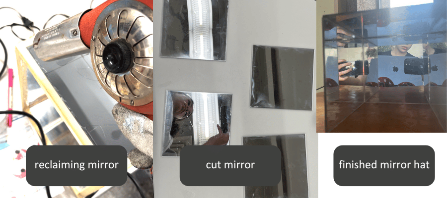
when all was said and done, i didn't like the way the mirror cube looked. it was dark, small, and the mirror was quite cloudy. i decided to keep it as a hat for my pomodoro timer instead of installing it onto the structure. it is a nice effect, but unneccessary for the project, so i decided not to use it.
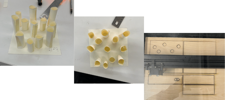
for the base, i needed a simple box to house the electronics, sensors for on/off switches, allow the cable to come out of the box. i knew i wanted to wire the LEDs UNDER the box so that it would be invisible, so i mapped out how i wanted the candles to fall. i had three candle sizes, and each of the candles had a diameter of .75", so I made the holes have a .6" diameter, big enough for the led to come through but not so big it would swallow the candle
after designing the base and laser cutting it out of this wood veneer i found, i used super glue to join it together. if i could do this again, i would have used wood glue. i added some magnets to the top of the (open) box and to the bottom of the lid so that the top face/lid could snap on and off the rest of the base in case i need to access the xiao or change any of the wiring.
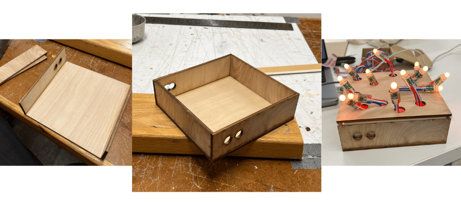
this magnet mechanism proved to come in handy as it enabled me to change around the position of the leds quite easily
i decided to cut the strip in half so there were no LEDs stored under the box, and it fit everything!
with the housing done, all that was left to do was make the candles. a feat i had been so excited for i saved it for last so i could see everything come together at the end.
first i designed a candle in blender. then i put a hollow cube around so that i could use the 3d print as a mold. i exported it as an stl and uploaded it to prusa slicer and multiplied it a few times. i then adjusted only the z-height so that i got three candles that differed only in height. the short candle is 1.25 inches tall, the medium candle is 2 inches tall, and the tall candle is 2.75 inches tall
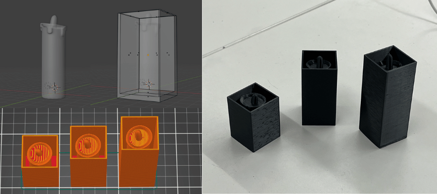
after printing the candles, i filled them with VytaFlex 60 rubber to make molds. this rubber was great, but it was suprisingly very hard.
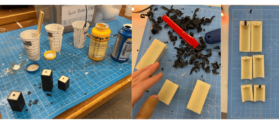
when the rubber was cured, i tried to demold them. unfortunately the 3d prints were very thin (not a lot of wiggle room for the rubber), and the rubber was very hard so i had to destroy the 3d print to get the mold out. i then cut the freed molds in half so that i could take out the candle part from the 3d print
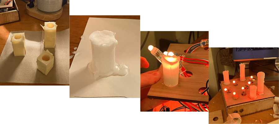
after getting the molds ready came the casting! i taped the molds together, and filled each with about 3 tsp of wax. i had a candle warmer and a candle on hand so i could melt the wax at my desk. i wanted the inside of the candles to be hollow so i moved the wax around so that it would evenly coat the interior and remain thin (that way the leds could sit inside the candle). i repeated this process 2-3 times
once i had a candle mold filled, i let it sit for roughly 20 minutes so the wax could cool. then, i demolded them. the molds snapped off very easily. i added a couple of drips of wax, and pressed the bottom onto a flat surface so that each candle had a skirt and could stand steadily.
after preparing twelve candles, i simply placed them on top of the LEDs with a bit of putty around the LED to secure them.
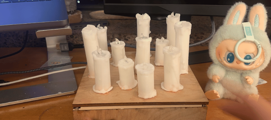
if i could redo these, i would make the molds bigger so that the candles could be thicker and stronger. i would also experiment with different ways of affixing the candles. glue doesn't seem to stick to wax, and while the putty keeps them in place, the overall structure is a bit fragile