Final Project
LIMITER: THE MICROTONAL ARCADE MACHINE#
I made a musical instrument that plays weird microtonal sounds but looks and plays like an old arcade machine!!

DEMO 1:
DEMO 2:
CONCEPT#
I love weird music.

That is the general quest which has sent me into the void of academia, in search of odd sounds and funky beep boops. In my research, I aim to make silly musical instruments and devices that give me the ability to find and harness weird these sounds.
One particular concept I’m interested in is play, especially as it results to musical gamification. As in, what happens to both the listening and performing experience when the music making process looks and feels like playing a game?
In this case, I want to combine my old nostalgic experiences playing arcade machines with my love of odd music theory concepts - in this case microtonality and alternate tuning systems. Basically, the tldr of microtonality is that our music is all wrong and out of tune - at least according to the laws of nature. We decided a long time ago to make our instruments just a little out of tune to give us the ability to play in all keys and have them all sound equally wrong.
Over the years, a lot of people have written music in the “correct” system of just intonation, although ironically it now sounds super weird to our modern ears. One example piece I like for reference is this by La Monte Young.
The problem I’m addressing is that its really hard to get musicians to play with the proper system of intonation! It’s hard to hear and your local string quartet will not be happy if I write a septimally tuned 7th chord for them to play. So I wanted to make an interface to harness these sounds.
tldr: I made a microtonal arcade machine
ANSWERING “DA QUESTIONS”#
f Q: What does it do?
A: It's a microtonal arcade machine! A cross between a wonky musical instrument and a game!


Q: Who's done what beforehand?
A: The concept of tuning lattices I did not invent, nor was I the first to notice that drawing shapes in those lattices looks kinda like Tetris or some other game. I was definitely to actually formalize this system into a musical instrument though.

Q:What did you design?
A: The machine itself, the graphics, all the parts, the code, etc


Q: What materials and components were used?
A: Three sheets of 4x8 MDF wood, black oil paint, a Raspberry Pi 4, a Pi Pico, a Teensy, a speaker, a Neopixel strip

Q: How much did they cost? (/ Bill of Materials)
A:
3x 4x8 feet MDF wood sheets - ~$200

1 gallon black glossy oil paint - ~$50

1 qt white primer - ~$20

Bose Solo 5 Soundbar (Speaker) - ~$168

Raspberry Pi 4 - $75

2x 64x32 Adafruit LED Matrices - ~$130

Raspberry Pi Pico - $4

Teensy with Audio Shield - ~$40

Neopixel Strip - ~$20

Heavy duty 6 connector power strip, 20 amps - $15

Arcade joystick + 8 buttons - $40

1x 48x36 Black ACrylic and 2x White Acrylic - ~$100


TOTAL: ~$822! (It took me and my lab a bit more than this in the end as I had to experiment with a few components that didn't work in the end, and had to buy some tools like paint brushes too)


Q: What parts and systems were made?
A: Everything but the matrix screen and the neopixel strip and the buttons I made myself!

Q: What tools and processes were used?
A: CNC cutting (A LOT), 3D printing (A LOT), lasercutting (A LOT), a little vinyl cutting, electronic design etc
SYSTEMS & DIAGRAM#
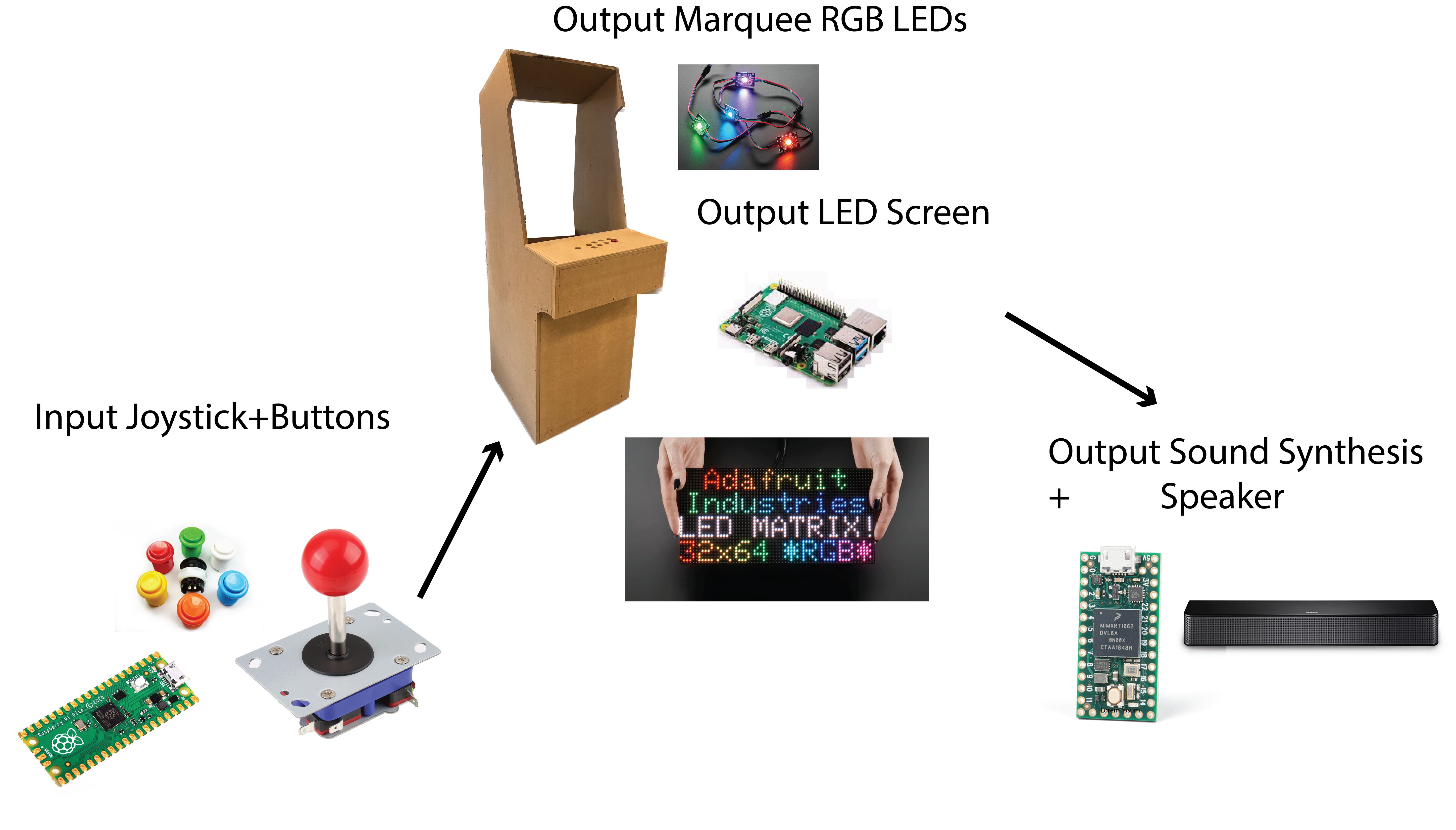
Basically, there’s a few parts to this.
One, the physical construction of the arcade machine (which I did in Make Something Big Week) and decorating it to make it look fancy and arcade like.
Two, the input joystick and button system, which I will use a Pi Pico for since I will need 12 digital pins (8 buttons + 4 way switch joystick).
Three, the sound output system, which I’m planning on using a Teensy for since I have familiarity with its audio library and it makes sound synthesis/playback very easy.
And four, the visual LED system, which will handled by a Raspberry Pi driving a big chained LED matrix.
These systems will talk using UART because its fast and easy and only requires two connections. And in my case, really only one because in these cases the chatter is one way.
SCHEDULE (from Midterm Review)#
Luckily, I’m pretty far ahead in terms of the individual systems working - they all do, but I need to now combine them. Also, systems integration is very important for me because I want this to be something that lasts for potentially years. I have a vision of it being a fixture in my lab space for a while and taking it to conferences and things, so I need it to endure the test of time.
| Task | Skills Involved | Status |
|---|---|---|
| Build physical shell | CAD, CNC, laser cutting, 3D printing | Near complete |
| Design logo and graphics | Design, Illustrator | In Progress |
| Make PCBs | PCB design, soldering | Not started |
| Install electronics | General fabrication | Not Started |
| Paint machine | Art, machine tools, spray painting | Not Started |
| Integrate all systems | Systems integration | Not Started |
| Test! | Not Started | |
| Compose piece to play for presentation | Music composition lol | Near complete |
| Week | Tasks |
|---|---|
| Nov 11 | Begin physical construction for “make something big” project. Order remaining sensors, LEDs, etc. |
| Work on each system individually. | |
| Nov 18 | Complete shell construction. Start designing graphics, order by week’s end. |
| Spray paint machine black for graphics, vinyl cut stickers for buttons. | |
| Design first PCBs for components; begin assembling systems outside the machine. | |
| Nov 25 | Thanksgiving Week – no physical fabrication. Work on musical composition and plan presentation ideas. |
| Dec 2 | Install electronics and graphics on the machine. |
| Dec 9 | System integration: focus on robustness, power supply, durability, strain relief, and PCB redesign if needed. |
| Dec 16-17 | Final presentation: playtest, gather feedback, and prepare showcase pitch and presentation. |
PROGRESS LOG#
Dec 14#
I came in today with the intention of cleaning up some of the physical presentation and honing some details that honestly most people will never see but still are important (to me at least 🥹). First and foremost was making a backdoor that could hinge so I could open it but also keep meddling kids away from the innards of it.
I stopped by hardware store and got some cheap brass hinges but sadly they were too long! So I used the bandsaw (with Dan’s help) to cut them down and screw some new holes. I then cut my back piece down just a little as the paint made it thicker.
After that they were perfect and it was pretty easy to install. Sadly it doesn’t fit perfectly in the back anymore, but I figure it doesn’t matter as nobody will really see it.
And then I made the fateful decision to try and hot glue my joints so they’d be more secure. Which caused it to stop working somehow 😵💫😵💫😵💫😵💫😵💫. And at that exact moment my command strips came crashing down and my screen fell off. And a terminal block came undone AHHHHH.
I was scared and super anxious, especially when my attempt to resolder resulted in shorting :(. At this point, I asked Alfonso for help who gave me some pointers and advise on how he would do this. I redid the joints according to his guidance and …. it worked again! (after many hours of pain and fear ahhh). I fixed the other problems and we were back to functional. Oh well - better today than presentation day, and now I am prepared for when things go wrong.
Dec 12#
I showed my advisor the finished product, and got some feedback on the musical systems. I also started thinking of Murphy’s Law, and trying to plan for everything that could go wrong. I think I have a pretty good idea of what subsystems are shoddly constructed and which aren’t so I started making a list of what I THOUGHT might happen.
Dec 11#
Today I put all together - I really had a hard time doing one silly thing - which was installing the joystick. The buttons were easy, but I realized I had kind of locked myself out from being able to screw the joystick in due to the super awkward orientation. I messed around for a while trying a bunch of stuff (stacking wood planks, didn’t work - tape, didn’t work, having someone hold it while I tried to screw it in, didn’t work). Ultimately, I simply glued it in, which (fingers crossed) has been holding quite well (and may it never falter).
I also added some zip ties to keep things a bit more organized.
Also today I finished up the programming - I had been doing it all semester actually but today I really locked in and got 👏 it 👏 done. (aha I have been living in the CBA shop for weeks pls help aha)
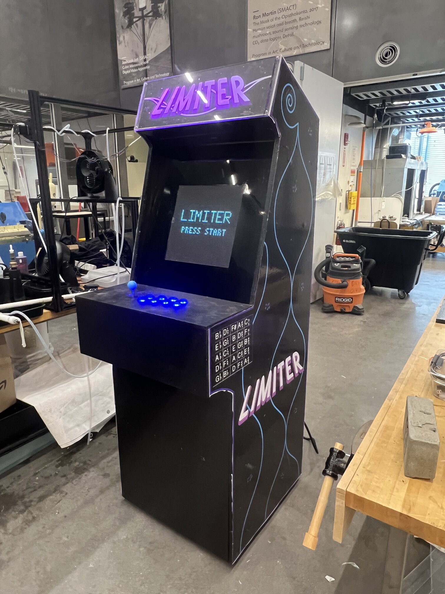
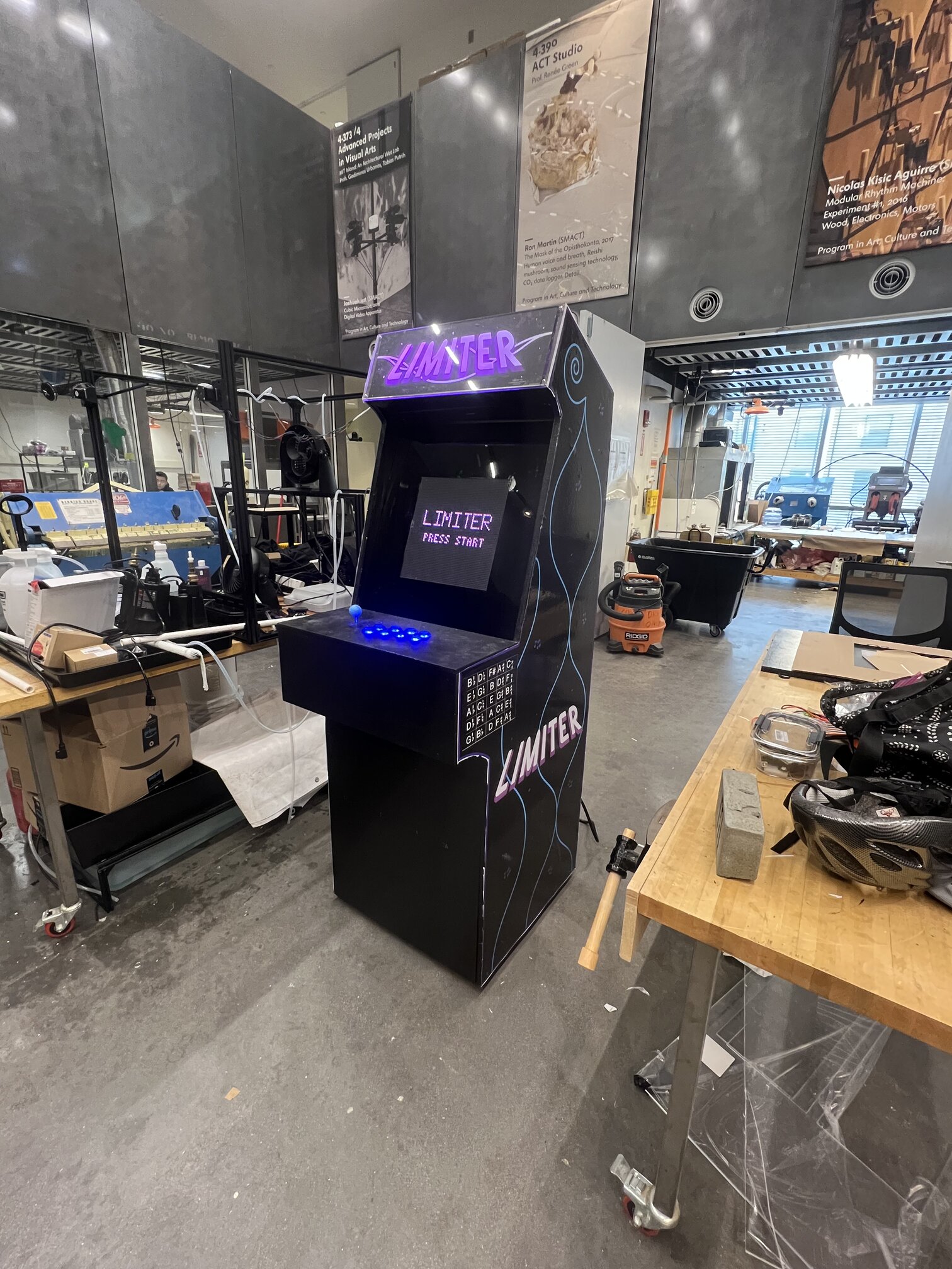
then…at roughly 11 PM I GOT IT WORKING!!!!! I was so happy I had the one other student in the shop at that hour take a video and it was great yay!!!
Dec 10#
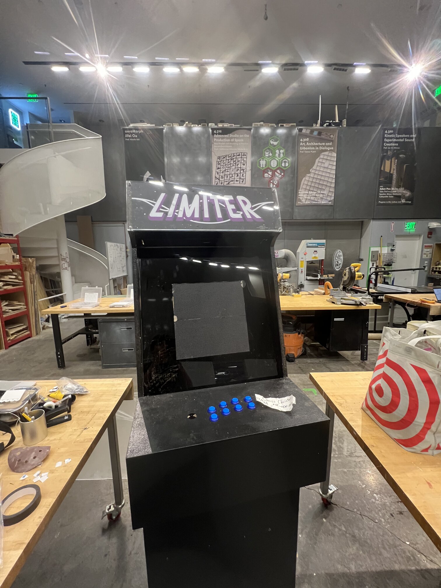
Today was the day I installed some graphics! I needed to lasercut some acrylic to mount the marquee so that was the first todo. It fit perfectly and I then stuck the marquee on, but I did kinda bad job and there was some air pockets sadly :( But actually in the acrylic it looks allllmost intentional - like some kind of asteroid or something.
A big question was how to actually mount the marquee - I settled on screws (the holes for which I lasercut) and it worked quite well actually - I was scared I’d crack the sheet, but it came out well.
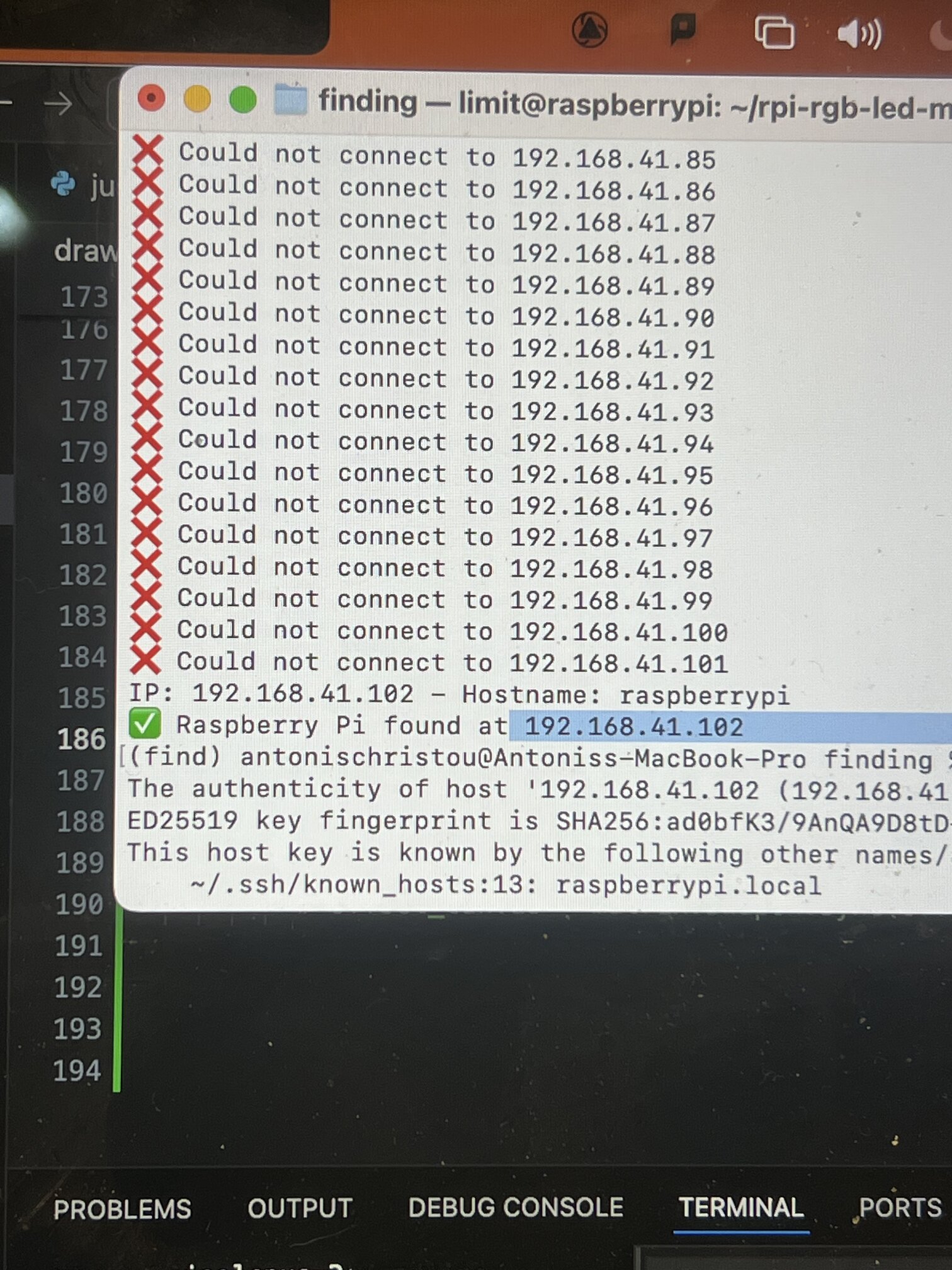
One super annoying thing is that it seems that MLDEV wifi doesn’t statically allocate IPs like I thought, so when I logged in I was very confused why suddenly I couldn’t ssh. I had no idea what the MAC address or hostname of my pi was so I had to resort to pinging every single ip on MLDEV looking for my pi lol….it worked though and I learned my lesson and requested a static IP From NECSYS right after.
Dec 9#
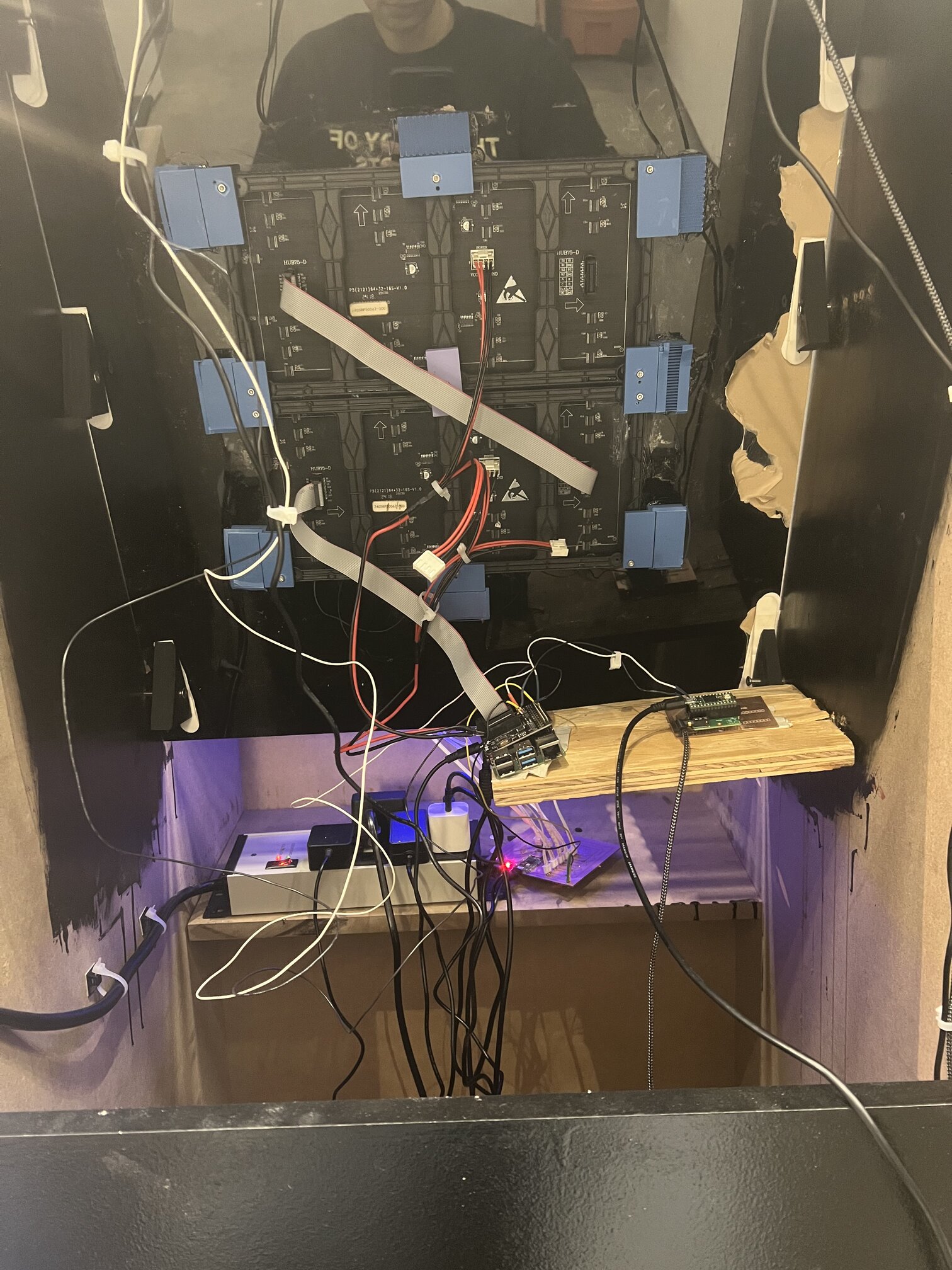
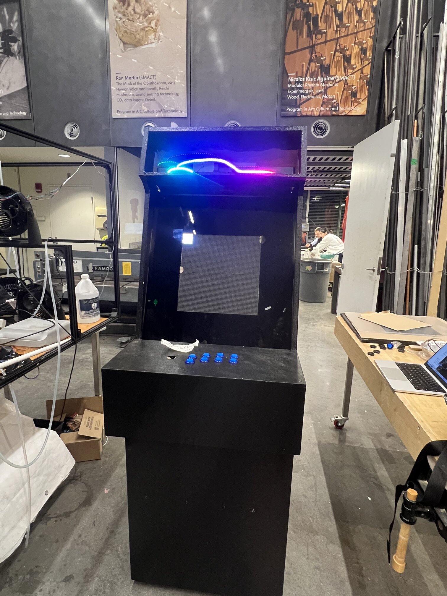
install day!! I put in my NeoPixel strip which would be the marquee lights first. I then realized my chord was too short for the raspi to reach the screens if I had intended to put them under the control panel like I thought so I quickly (and a bit shoddly for now) installed a wood plank I found in the shop to mount them.
It was super awkward moving my boards into the machine - I think in the future I will think more carefully about when and how to solder things so that things are easy to transport.
After putting everything (with the UGLIEST and sketchiest setup of all time with the wiring for now) and tested each subsystem in isolation.
Neopixel strip….check
LED matrices….uhh the terminal block connectors fell out at first and I had a really hard time getting them back in with the physical setup restricting my motions. The same thing actually happened with the NeoPixel strip a bit later but I managed to fix it (with so much stress and anxiety ahhhh).
Testing buttons….check
Testing audio….didn’t work at first and I saw with the USB Logic Analyzer that the UART was being sent but not reaching the Teensy, due to an incinerated trace. I had to (very carefully and gingerly) resolder directly to the Teensy, but it at least worked.
Dec 8#
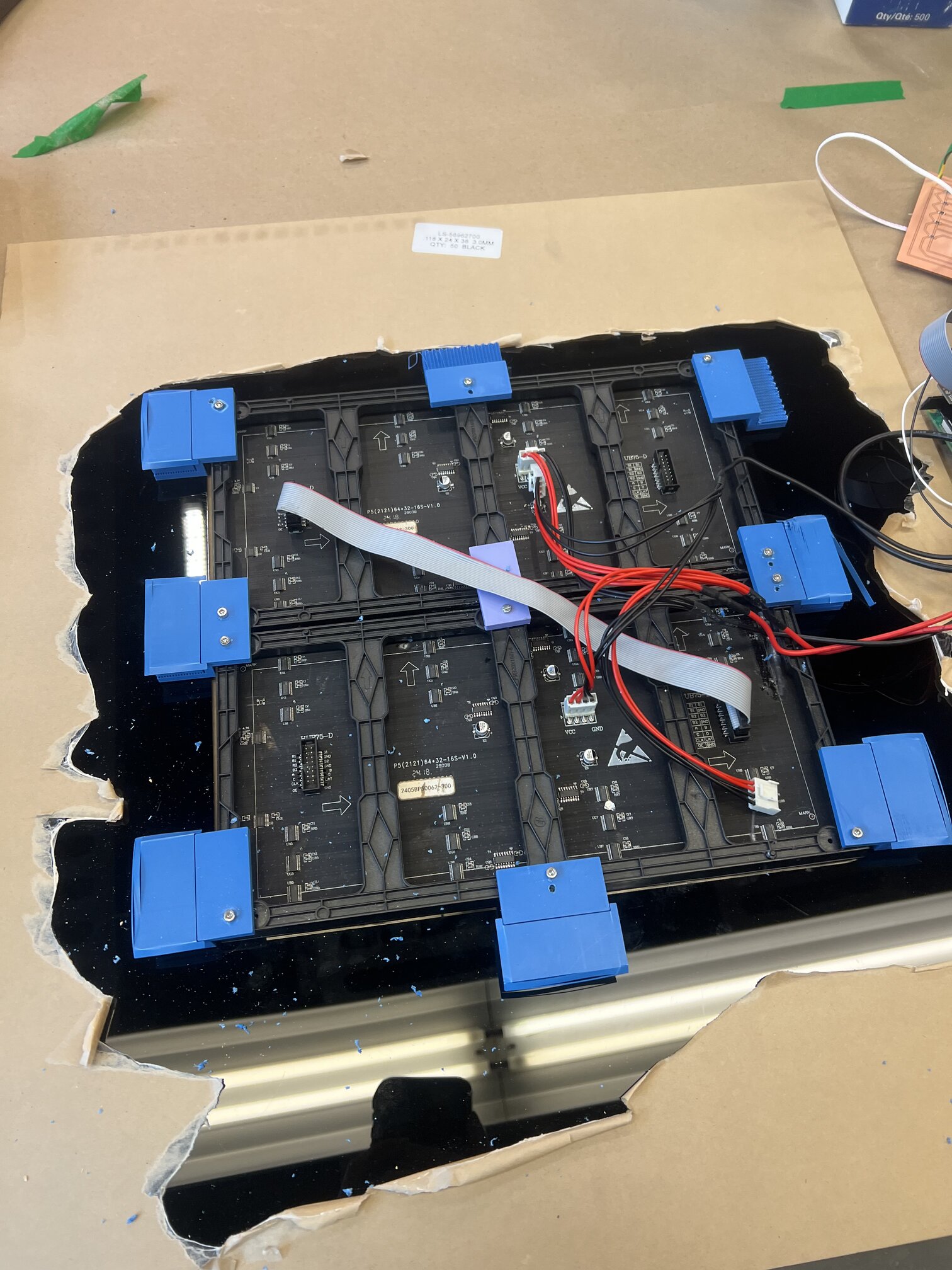
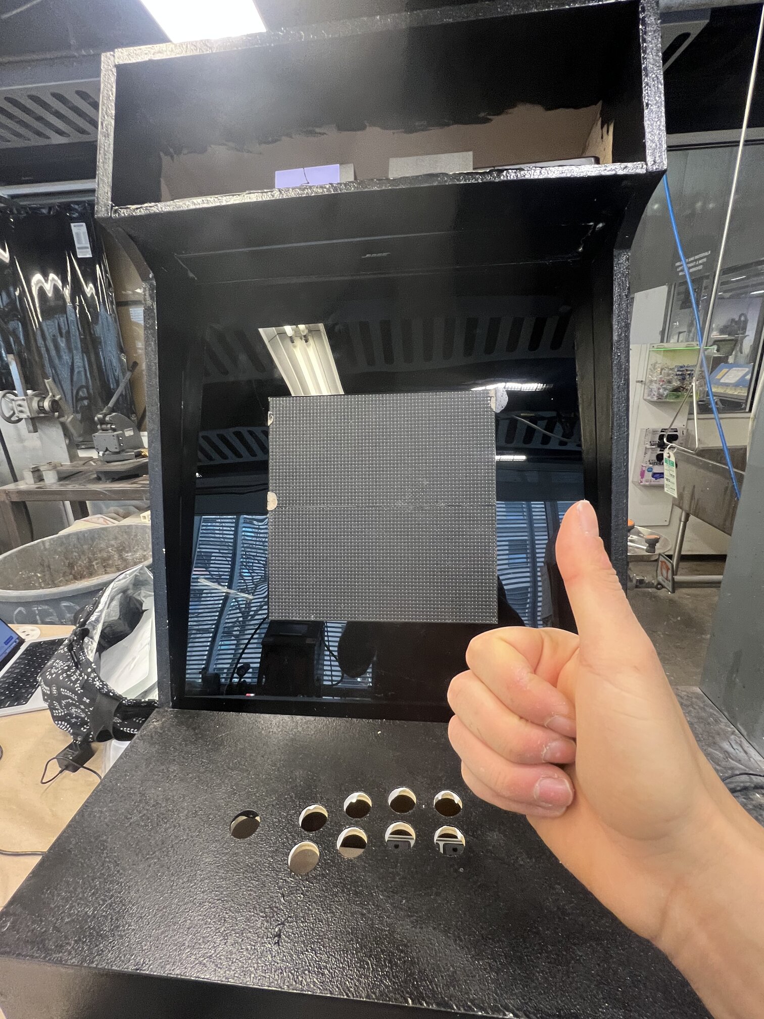
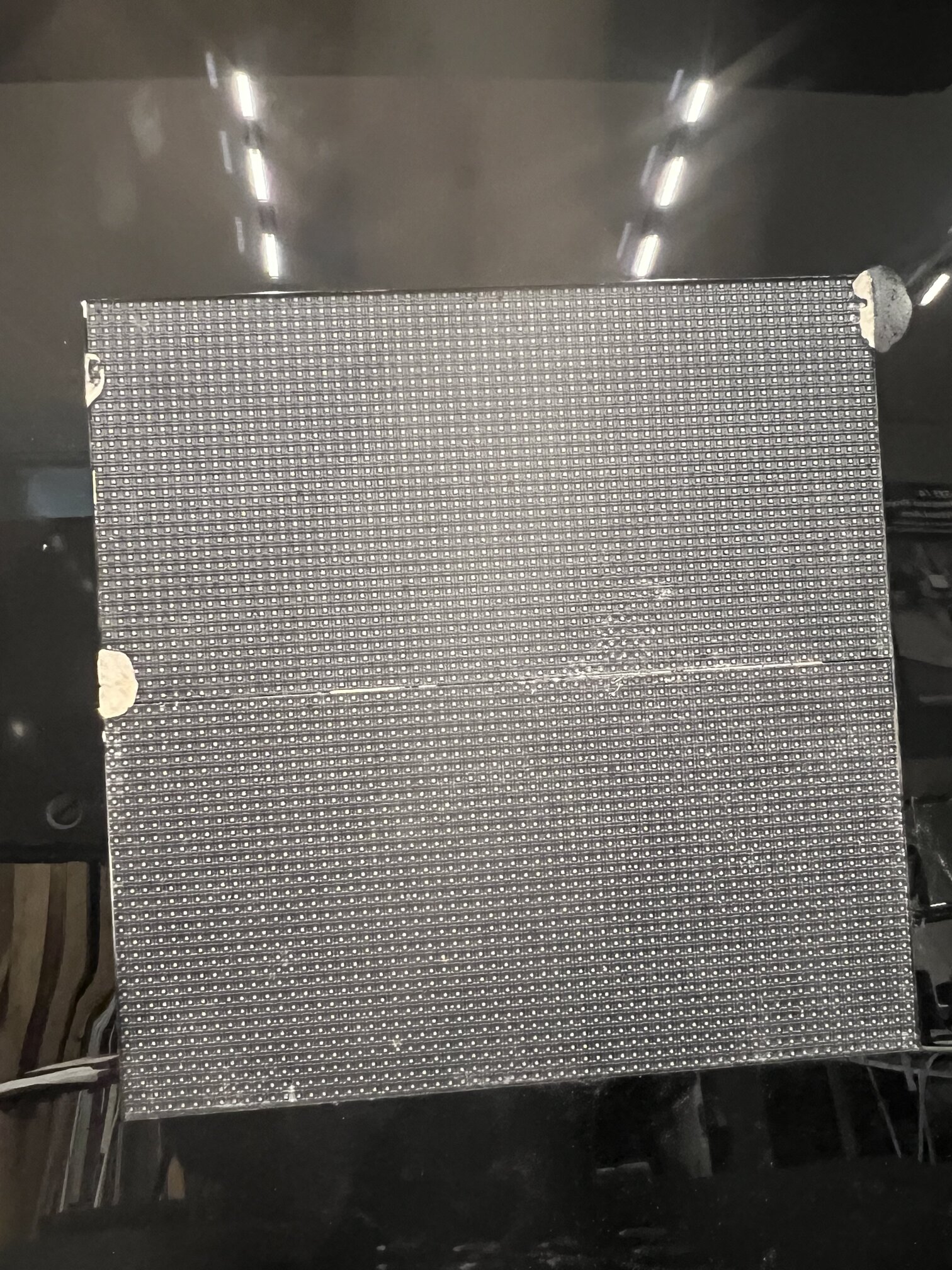
For installing the screen into the matrix itself, Alfonso suggested I make (yet more) 3D printed brackets and use something like command strips so it would be secure but removable. I liked that idea so made 6 triangles at roughly 70 degrees and drilled them into the sides. I then attached the command strips (thanks Alan!), and stuck the screen on and BOOM - this thing is starting to look more legit!!!
At this point, random passerby in the CBA shop would come to admire it, and many asked often where I got the machine frame itself which I laughed it since I guess that’s the ultimate sign that I did a good job.
Dec 7#
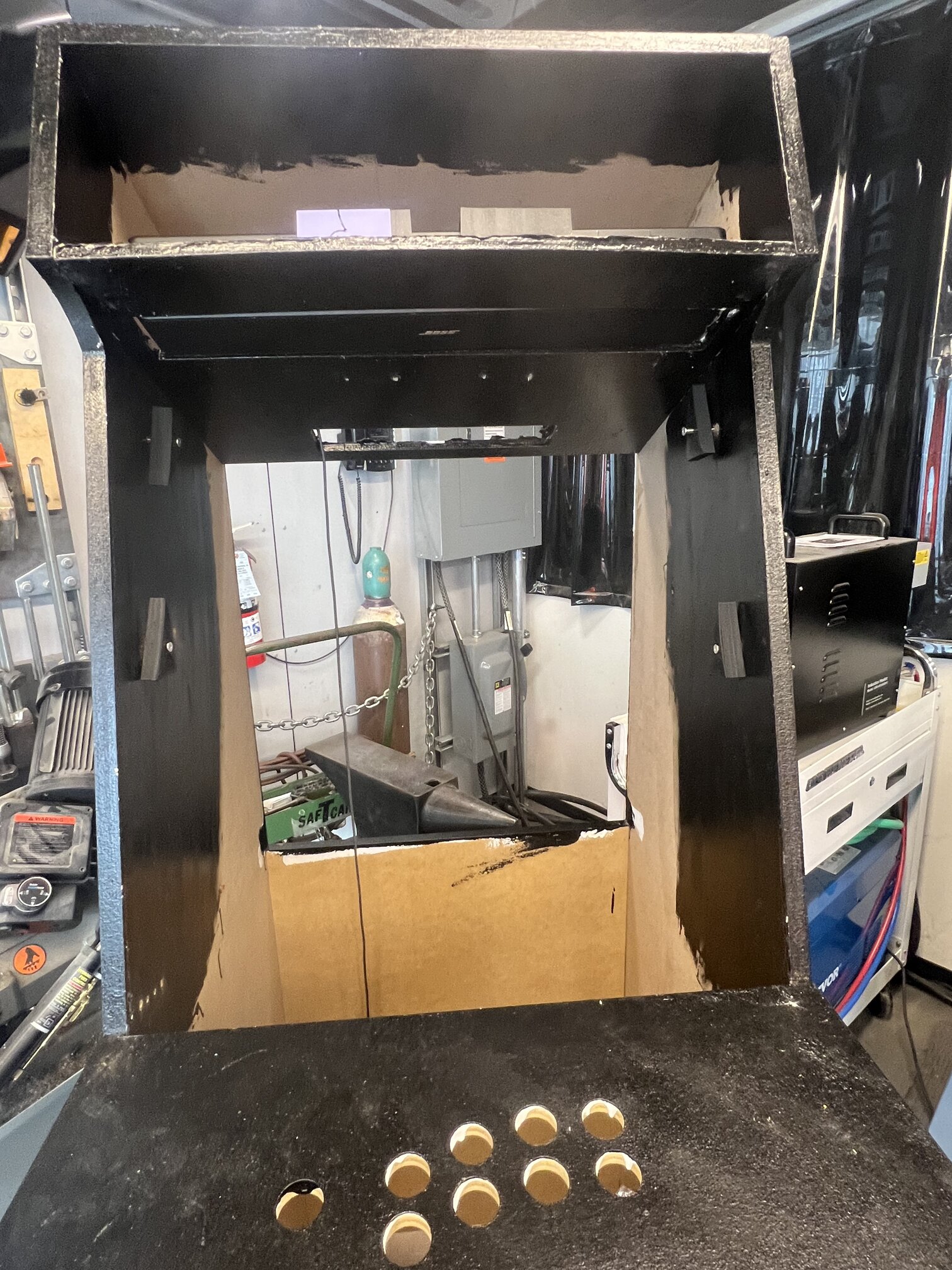
Now came to time to make the screen harness. I had this beautiful box but I had no idea how to put screen inside of it. First step was well, make the screen. I got some black acrylic from Alfonso and laser cut it after a few cardboard tests.
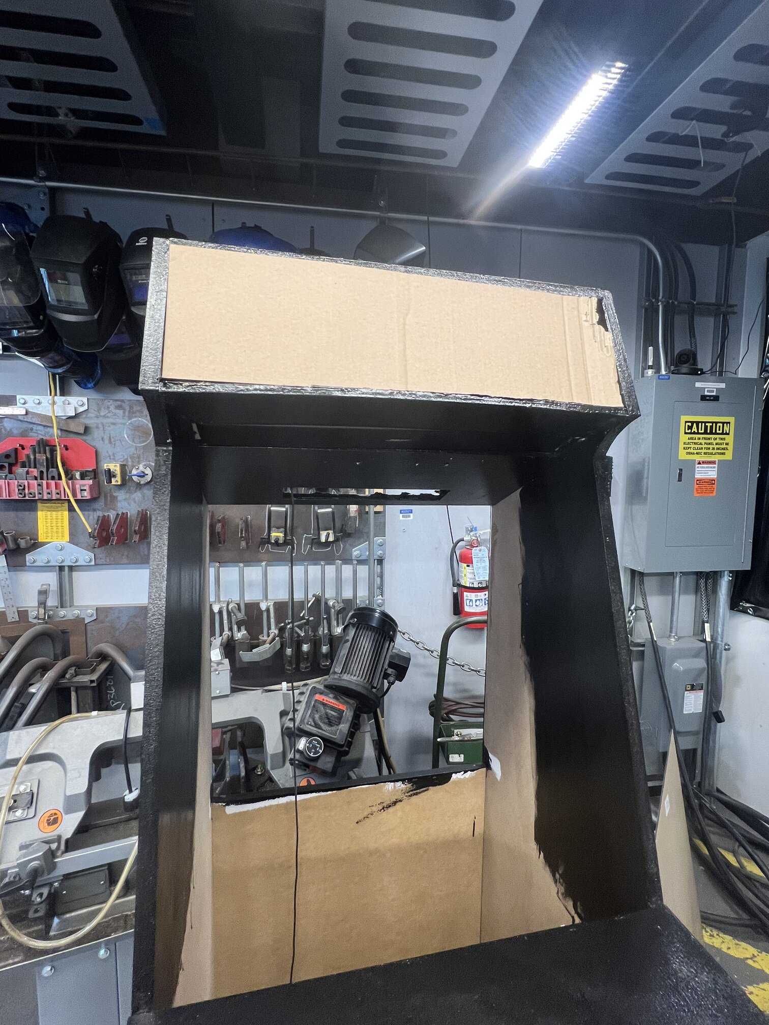
Sadly, the screen was a liiiiitle too small so I had to sand the edges so my matrix just fit in. Next, I made a bunch of 3D printed brackets just like I did for the speaker and screwed them - amazingly I got right on the first try! I’m getting better at this? Maybe? Now for adhering the PLA bits to the acrylic (which I didn’t want to screw into for a lot of reasons), I settled on glue. I first tried glueing a test PLA square I made into my spare acrylic with superglue, which was ok but failed as soon as I applied pressure. Some google searching indicated that something called “Weld On 16” might work, and we had some in CBA so I gave it a try with my other test square. In fact it worked so well I physically could not remove the square from the acrylic wowsers. So I used of that on my matrix, and prayed that I wasn’t making a huge mistake and went to town.
It worked great, except for the one detail that some glue seeped through the seams and got on the screen face and that’s never coming off I think :((. Even worse, some bits of paper stuck to the front which I had to carefully weed off with a knife. Ugh I suppose I will have to live with these surface imperfections sigh.
Dec 6#
At this point, I had all my boards working and communicating with one another yay!!!!
….and then the next day the audio board stopped working why :( It turned out that it was due to somehow the connection getting fried from the header to the Teensy pin itself. I think that maybe when I was soldering it must have burned it off or nearly did, and it suddenly failed as a result. This was sad mostly because I very carefully had things heat shrunk well but alas. I remade and it was ok!
Dec 4#
For the matrix board, I needed to make a two layer PCB, so Quentin kindly showed me how to use the via press machine thingy. It was A SUPER FRUSTRATING PROCESS because often the holes would be ever so slightly off when I flipped the board to mill the other side, and so wasted like 5-6 attempts on boards that didn’t work. I think I would see if there was a different way of doing this in the future.
Dec 1-3#
Now came time to install the speaker panel, which I had carefully CNCed out of plywood in CBA. Sadly, the panel was a touch too small for my speaker, so I had to sand it down just enough so that it would fit. I needed an extra pair of hands for the install, and Nina very kindly helped me out. After a few minutes of wacking, hammering, and drilling, we got it in!
A long story short was the question of how to actually install the speaker into the panel in a secure way. I initially thought of using some kind of pre-existing bracket, but there was nothing I could find that fit the weird shape of the speaker. So I thought of 3D printing my own brackets, even though I had no idea if they could hold. Jonny and Anthony gave me some pointers on how to design structurally sound 3D printed PLA brackets, so I made a few variations:
The first ones were too flimsy and I could snap them with my hands, so I added some supports and fillets for strength.
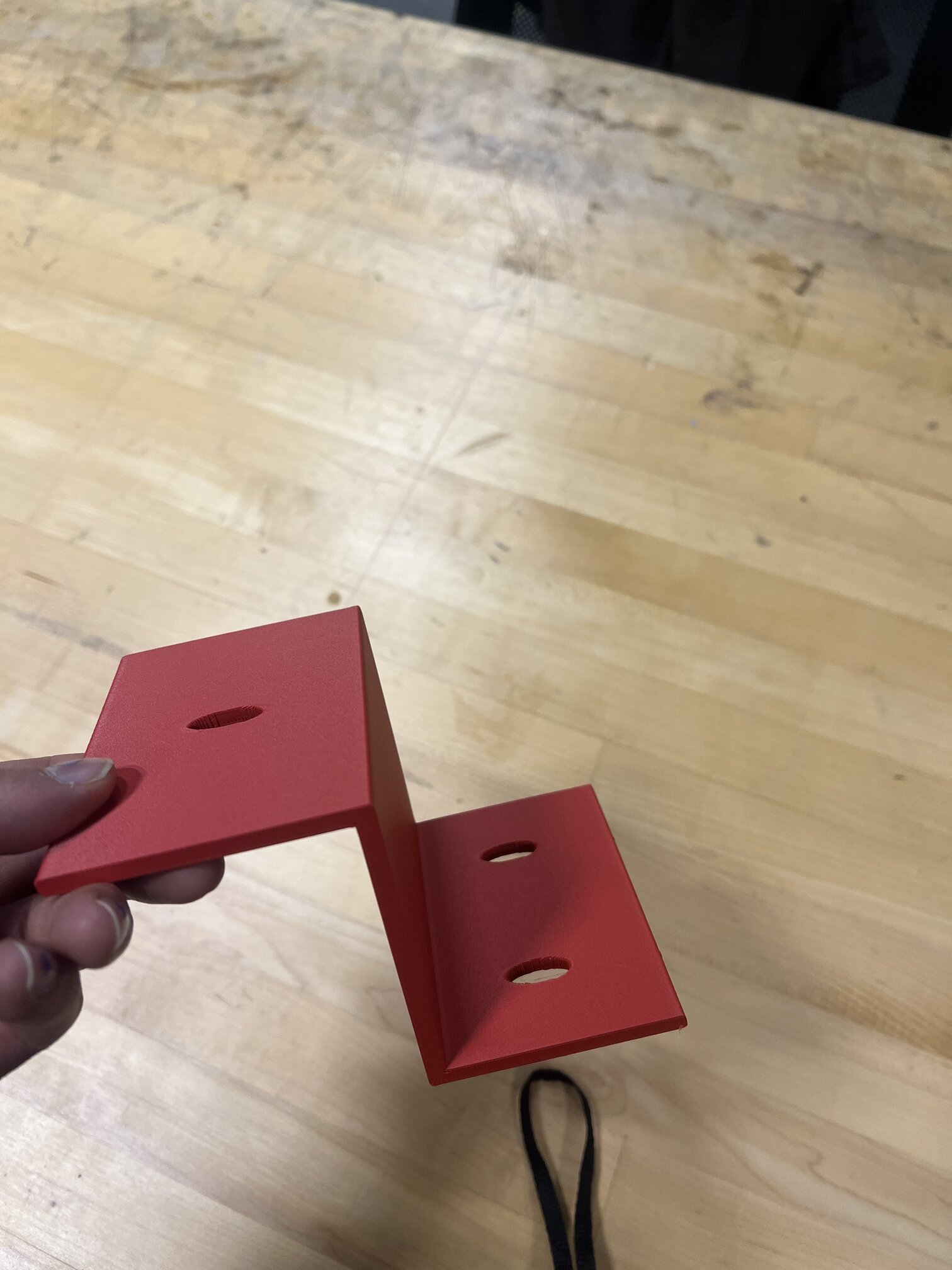
Next one was good, but just a liiiitle too small :(
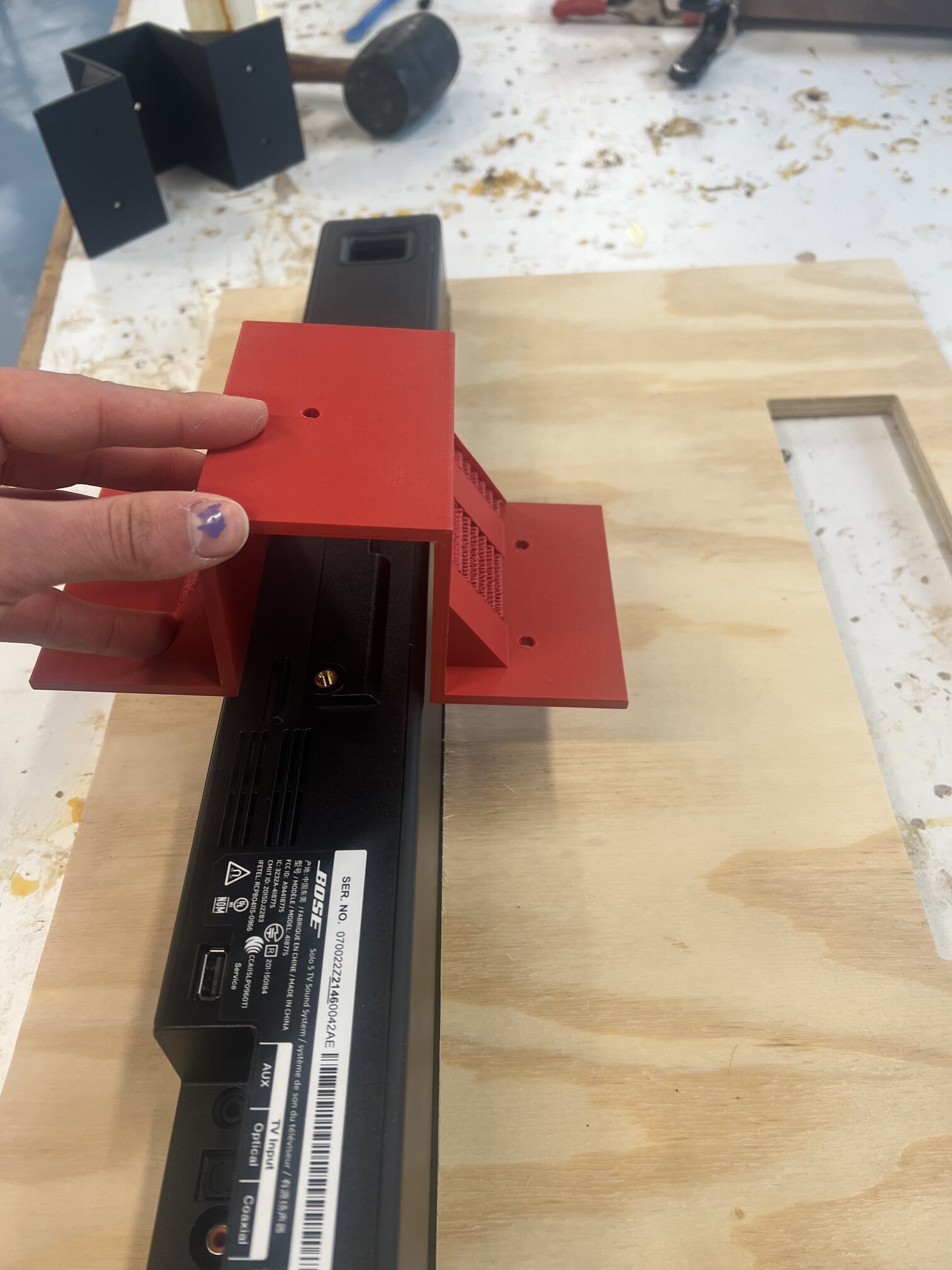
Third time was the charm! I then screwed it in to the speaker itself, mounted on the board and we were ready to go! These were long, chonky prints, and maybe one day in the future they will fail and plop on the face of someone playing, but for now they seem quite secure - I hung them upside down overnight as a test and it held strong.
I then went through some more PCB button board trial and error, trying to get it just right with the holes and the headers and the UART, eventually getting it working.
Nov 22#
Ok! Thanksgiving break time so no fabrication. In the spirit of supply side time, I gave myself two days to work on designing a cool graphic. I had wanted to cut the graphics myself, but obviously vinyl cutters can’t do it since they’re just printers, so Anthony said to just try CopyTech or some print shop.
I am absolutely not a graphic designer, but I kinda liked the chance to try and do something artistic. I was really adamant that I DID NOT WANT IT TO BE AI ART GRRR because I really dislike it. Although my research has to do with AI-human synergies, it didn’t feel right to use it, plus I didn’t really like the results fully. I did, however, in the spirit of co-creation, use it to generate ideas of what it COULD be in the early stages.
Aesthetically, I always loved 80s sci-fi for its speculative vision of the future, imagining what the world could look like - its very Media Lab if you ask me. So for my musical instrument arcade machine of the future I wanted to channel that kinda cyberpunk, futurstic, Tron-y vibe, while still making it clear that it was in fact, a musical instrument. After a bunch of variations, I came up with these:
and sent them to a print shop to get them done. They came back right when I returned and were perfect!!!
![]()
![]()
I was going for a vaguely “sin wave-y” design to show the spirit of the tuning system that my microtonal arcade machine uses, which is just intonation based on the pure harmonic sin ratios of nature.
Nov 18#
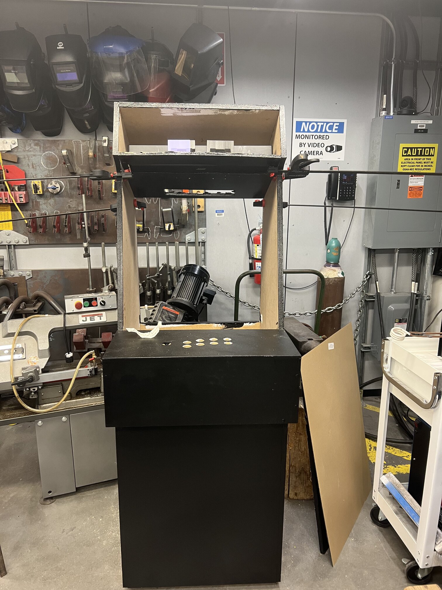
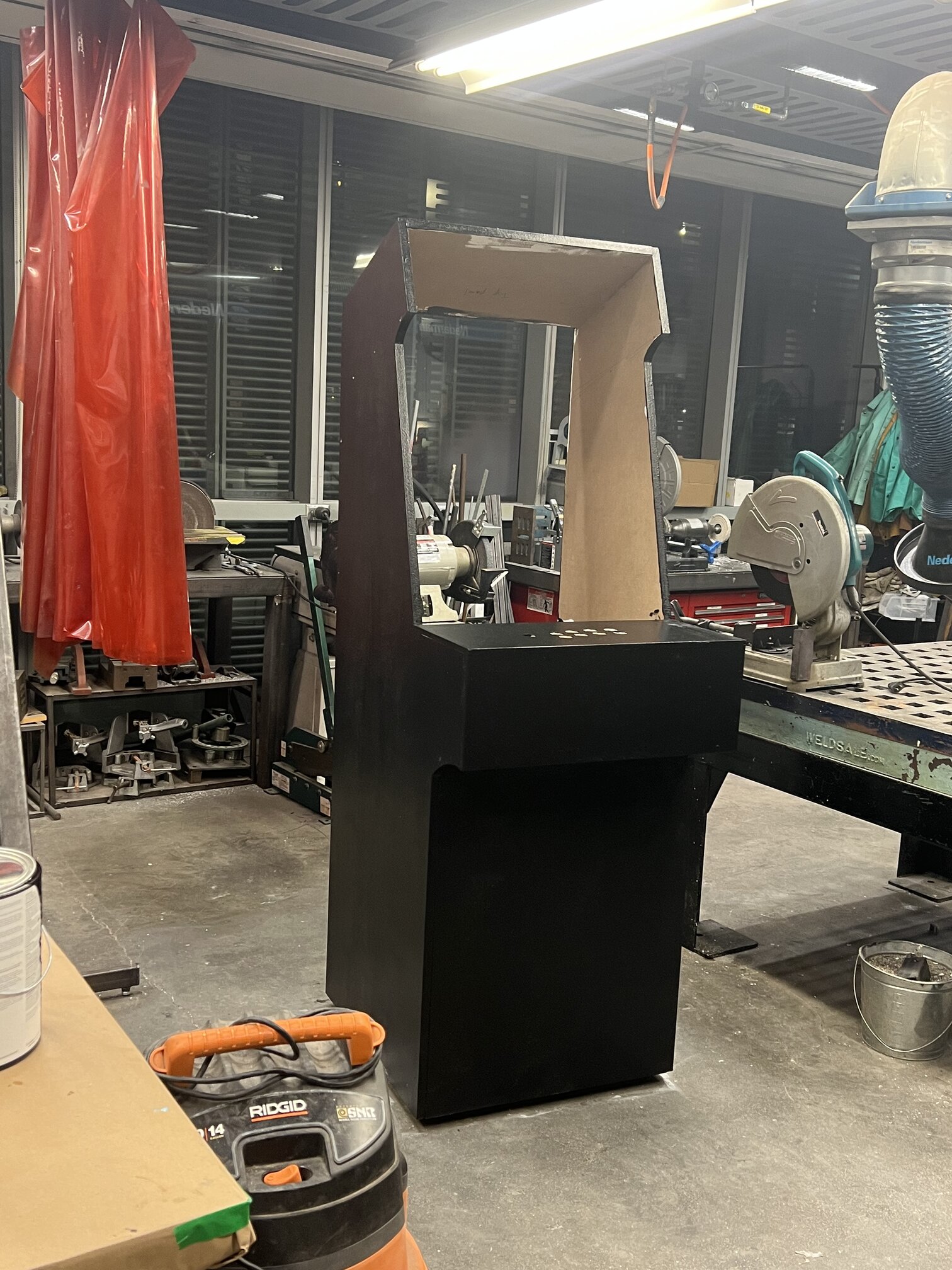
So while I used the Arch Shop CNC due to the fact that I was dissuaded from cutting MDF in the CBA, I did eventually need to move it to CBA land as that is where my home and heart truly is <3. Also, there was no place to paint there (I tried REALLY hard to find somewhere to spraypaint it but there was no where big enough :((. So began the long Odyssey back to CBA…
Ironically this is like a 5-10 minute walk in most circumstances but pushing my machine (which has wheels thank God for my foresight on this) down the street…in the rain…..with my gear… took like an hour. On the bright side, despite hitting a BUNCH of bumps (wow streets are not even….) it made it safe and sound with just a few wood chips popping out. So I learned that my assembly job was pretty good actually (best stress test ever huh).
I learned that it was actually a lot easier to push it in the street rather than the sidewalk because it was smoother, and so gave many passing cars probably the strangest view they’ve ever seen.
Now came painting time! Graham of ACT and Dan of CBA shop and Alfonso had loosely said I could bring it CBA, but I think Dan was a biiiit surprised when he saw how big it actually was. (Oopsies sorry Dan, thank you so much for letting me work on it there <3). I enlisted a dear friend who was way too kind in helping me a bit, and got some oil paint and rollers and a brush and went to town. The process was:
-
very light sand as the MDF was already very smooth (but I also had a few plywood planks I cut on the CBA shopbot that needed to be sanded down a bit)
-
primer to help the next layers
-
paint, two layers of oil paint, seperated by a day each
(and then the secret 4th one, cleaning the floors so Dan wouldn’t be sad…)
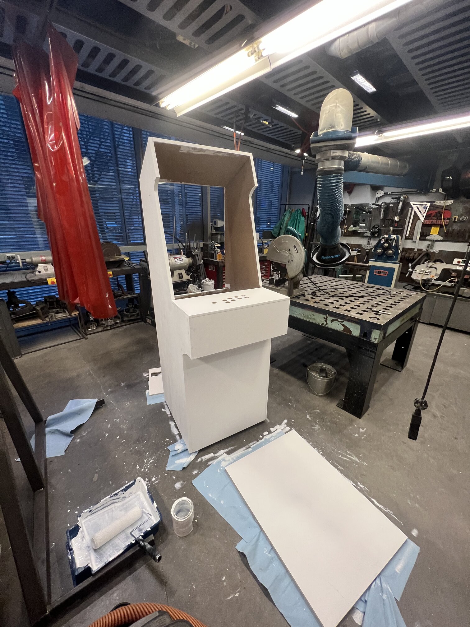
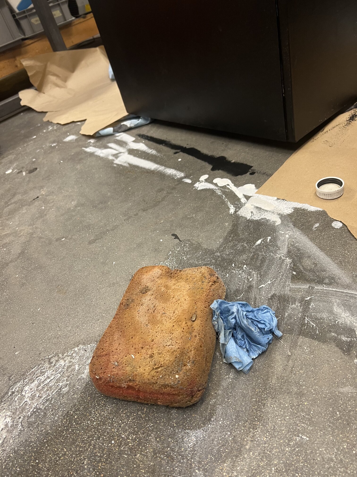
Overall, the whole painting process took two days, but it was actually one of my favorite parts of the project. At many times while working on this, my emotions were mostly fear and anxiety that I would terribly mess something up, but this went pretty smoothly. The final result was pretty even, if a bit thick and a bit goopy in some places. Oh well, mission accomplished!
NOTE: I actually barely had enough primer but had way too much paint that I then did not know how to dispose of, so for future travelers here, do carefully account for how much you need.
Nov 13#
Wow pico has like no mem: 3d list creation makes it OOM very fast thus making it not well suited for my musical operations sad :( As a result I changed this pico to a raspberry pi due to its power and ease of use. Also, being able to ssh onto the Pi to upload code makes things much easier than having to reach in and plug stuff everytime I change one variable.
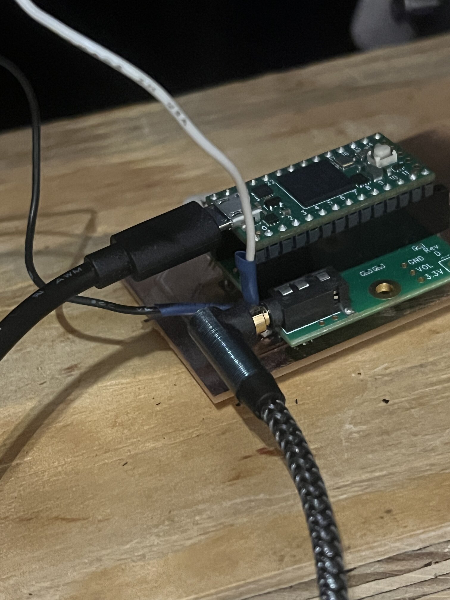
Basically the full schema is the lights Rasp Pi is the “master controller”, receiving input from joystick/pico system, and sending to teensy for sound synthesis.
I am doing this with UART due to the few wires required and the simplicity of the protocol I actually need - I am sending quite simple information, just like “play these notes” or “these buttons are pressed etc” so nothing fancier is required. Plus, I learned you can “split” a UART connection from Anthony so that the RX and TX wires are actually pointed at different microcontrollers, thus making it even eaiser.
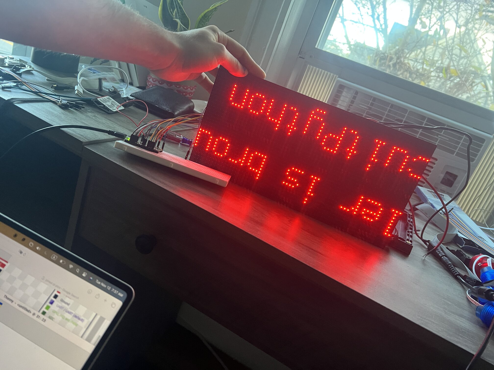
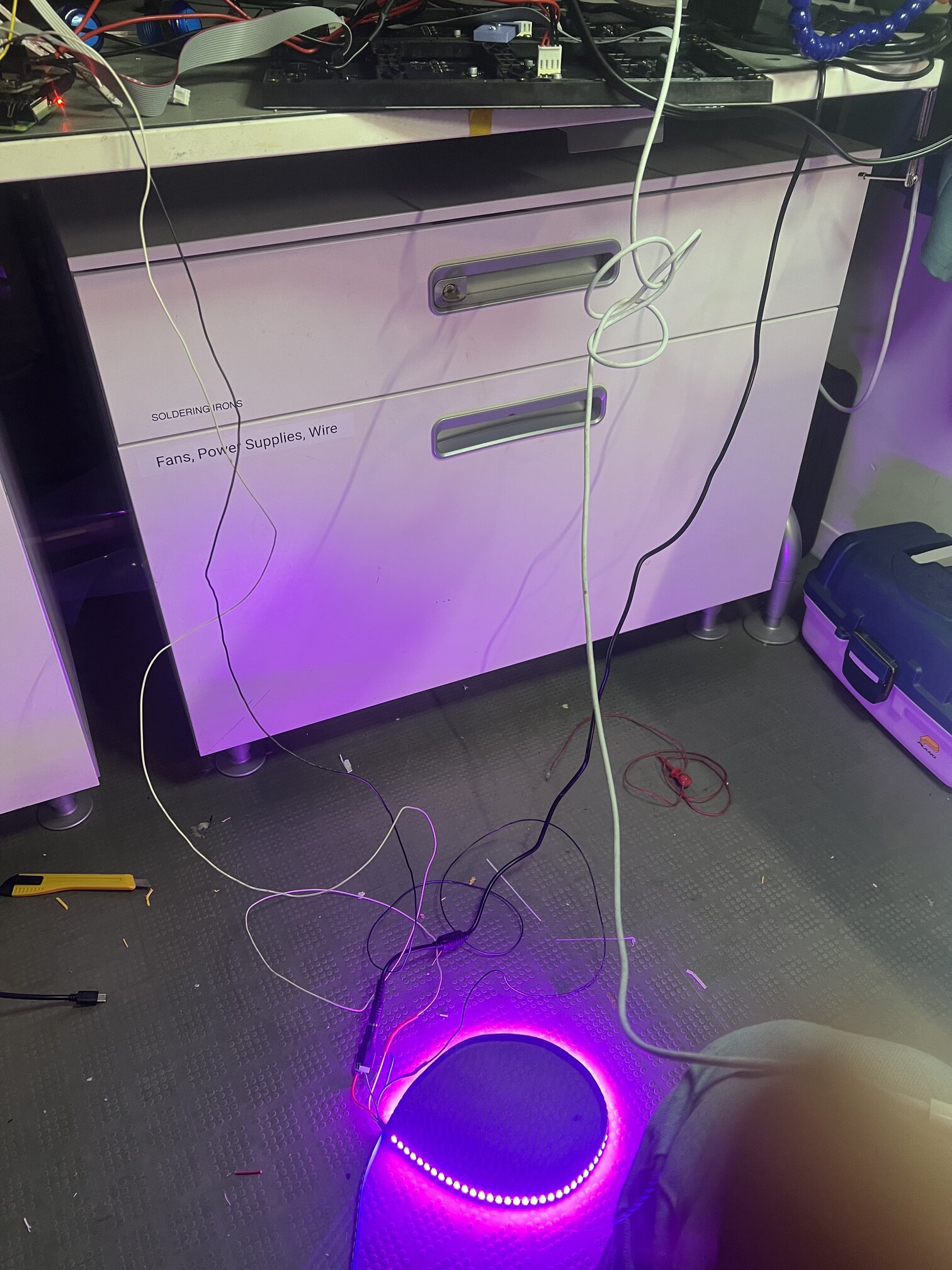
My speaker came, and I got the sound system online. I was worried that it would somehow be not compatible with the Teensy for some reason but it worked great and was super loud if I cranked it!
I also tested my Neopixel strip which would form the lights for the marquee - it was very easy, a quick solder job and a simple connection to a GPIO pin:
Nov 12#
At office hours today, Erik helped with system integration .how many microcontrollers….how to power them…those kind of questions. His and Anthony’s advice was simply to use a power strip inside my machine connected to everything so I could just plug it in the wall and call it a day with only one outlet. I also as a result of this conversation settled on a Pi Pico for inputs, a second Pico for visual output, and a Teensy for sound output (although this would change later, if you read above where I changed to Raspberry Pi for outputs due to memory issues).
I got the matrix wired and working again in a breadboard although I almost killed it by accidentally putting ground and power in the opposite terminals whoopsies.
Now time to think about integrating and porting everything into an actual machine.
Nov 9#
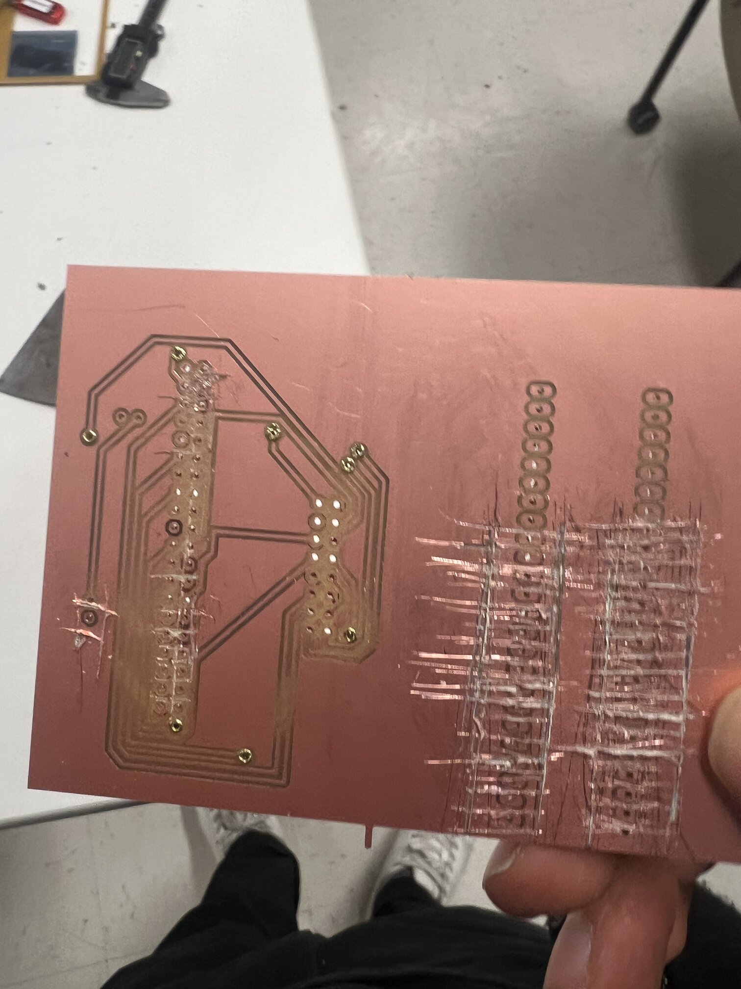
I was now thinking about my PCB design - I need a Pi Pico for my input devices (a bunch of buttons and a joystick, which itself is basically a bunch of buttons), so I began designing and making some prototypes.
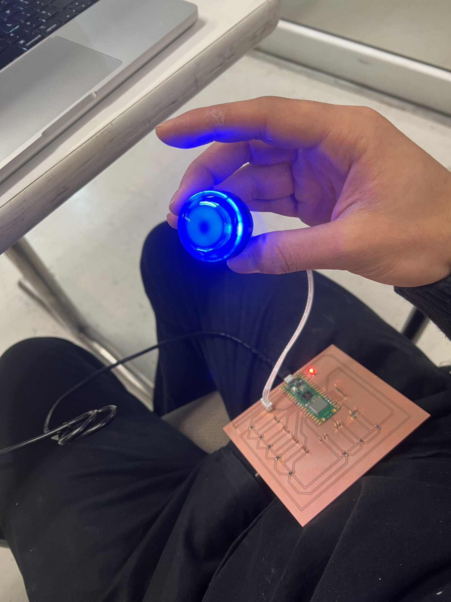
However, as usual I was stymied by the fact that I suck at soldering and also have no idea how to connect things. I made a bunch of mistakes as well getting the Carvera to do through holes, but Anthony and Quentin and co, as usual saved me there.
I made a bunch of failed boards, which were the result of either the holes being too big (I needed to use Quentin’s Gerber2Img STRONG RECOMMEND) or using too short headers so that my buttons couldn’t even get on after putting solder on them. I also messed up at least one board due to simple shorting things very badly :(((
After that I had a basic test of what I wanted that seemingly worked! In software the one issue I ran into was input pullup vs pulldown resistors - for future reference / posterity this was the result of my investigation of what they are and what the difference is:
Pull up resistors connect a given pin to the supply voltage, thus keeping them HIGH by default, while pull down keep them at ground, therefore keeping them low. In the button case, pushing it down gives the current a new path, thus reading the opposite value. Therefore, it’s important to set them properly in accordance with your hardware so it is read properly!
See my networking week for my details on this board and this process! But here it is working with UART to send messages to my Pi:
Nov 8#
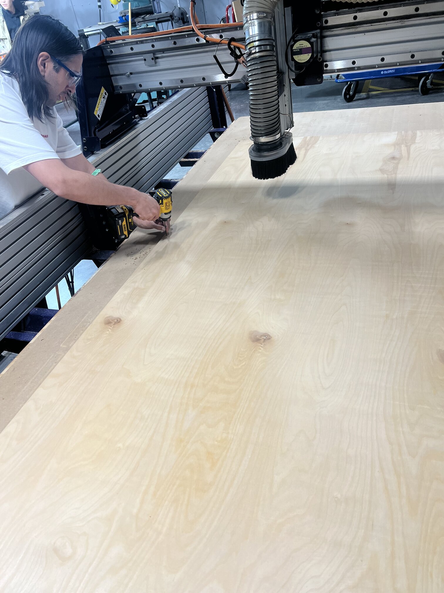
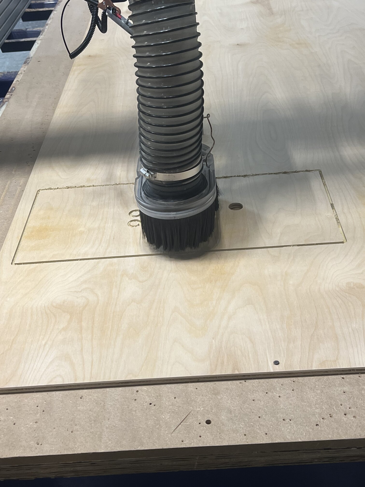
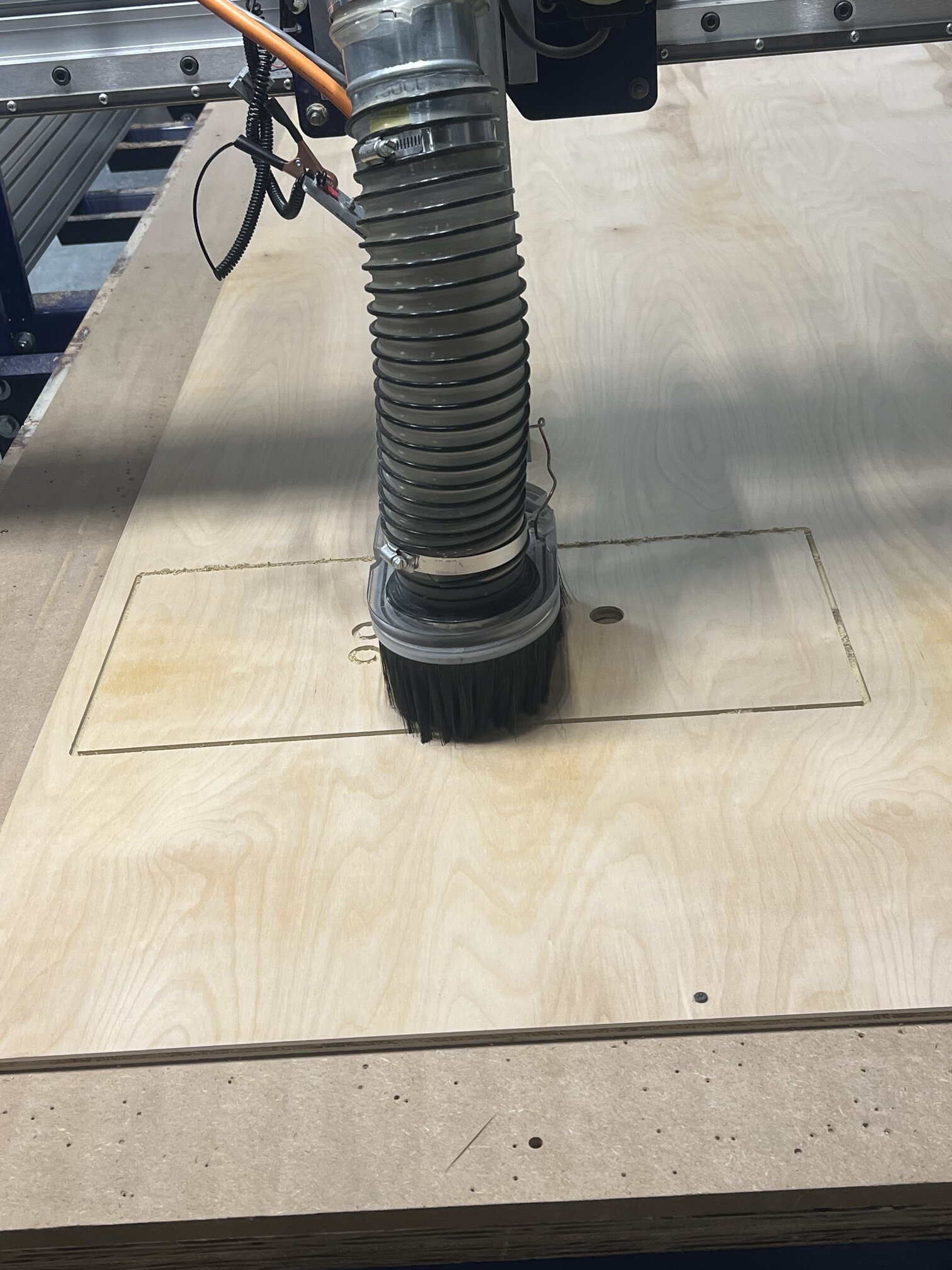
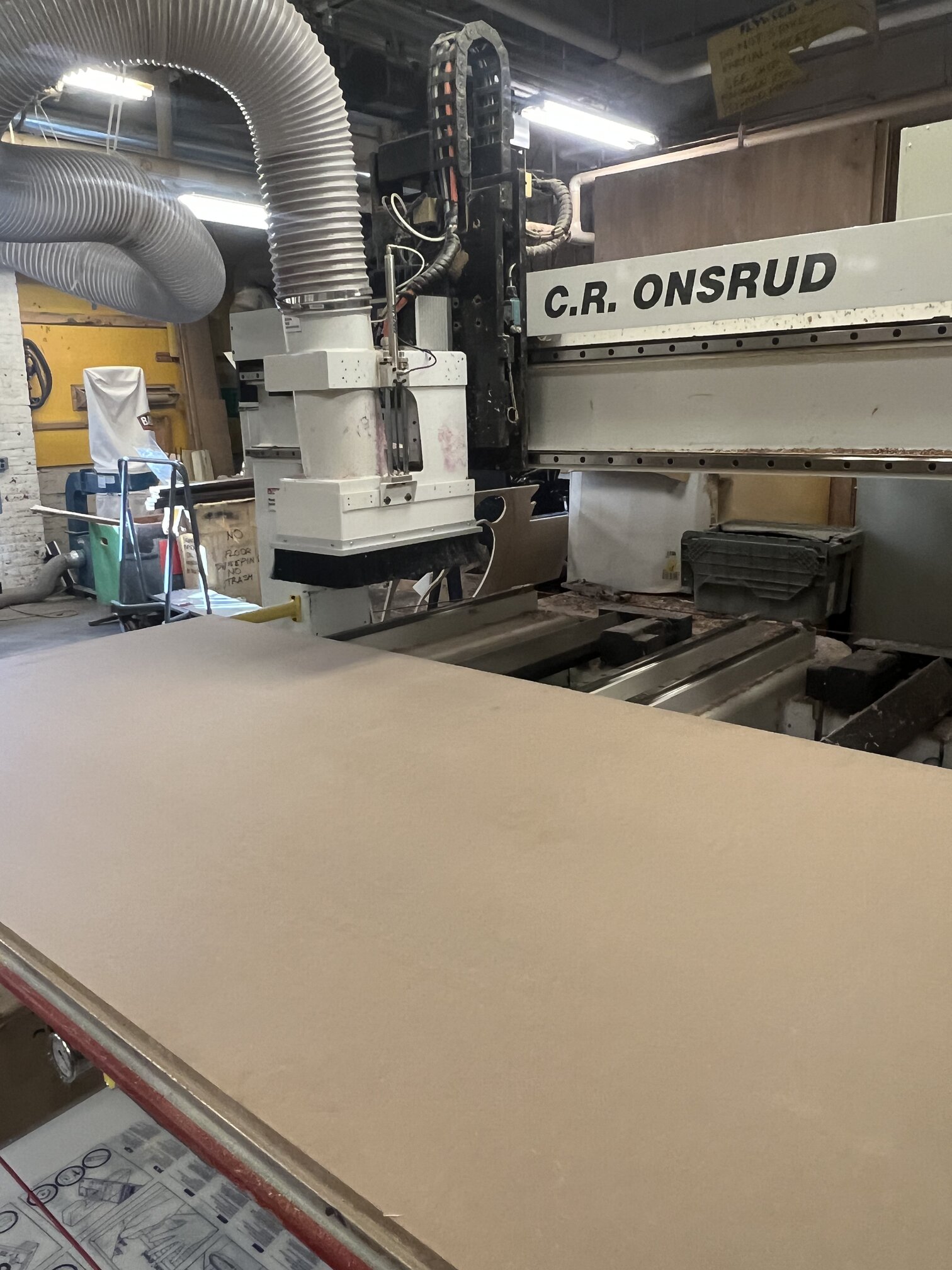
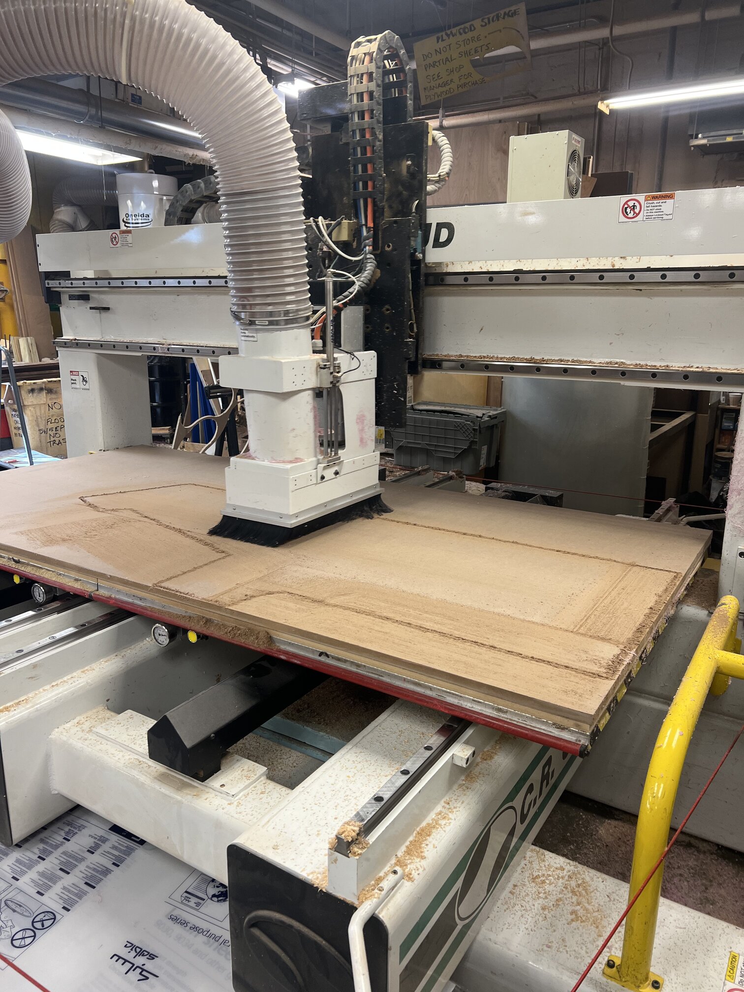
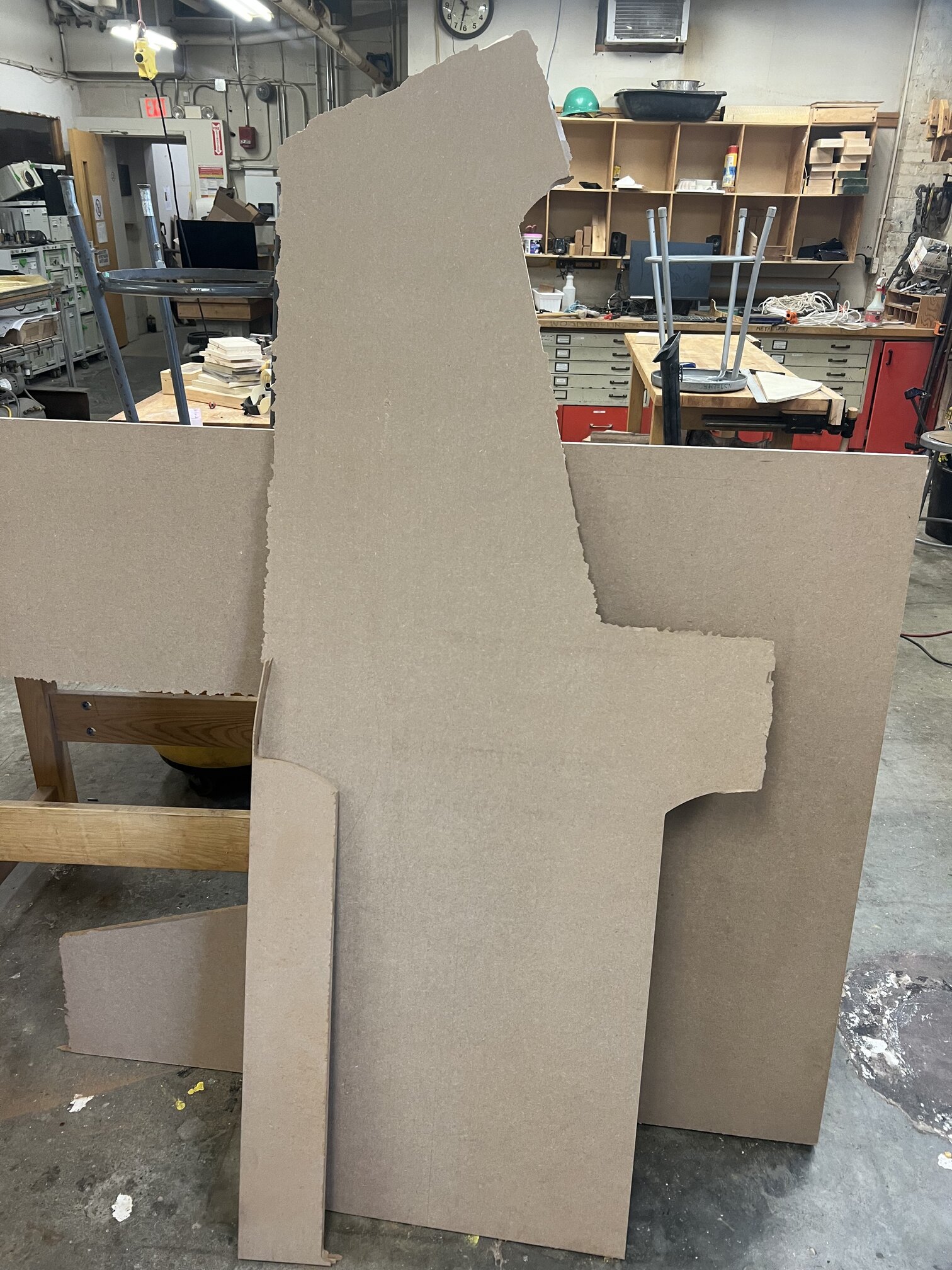
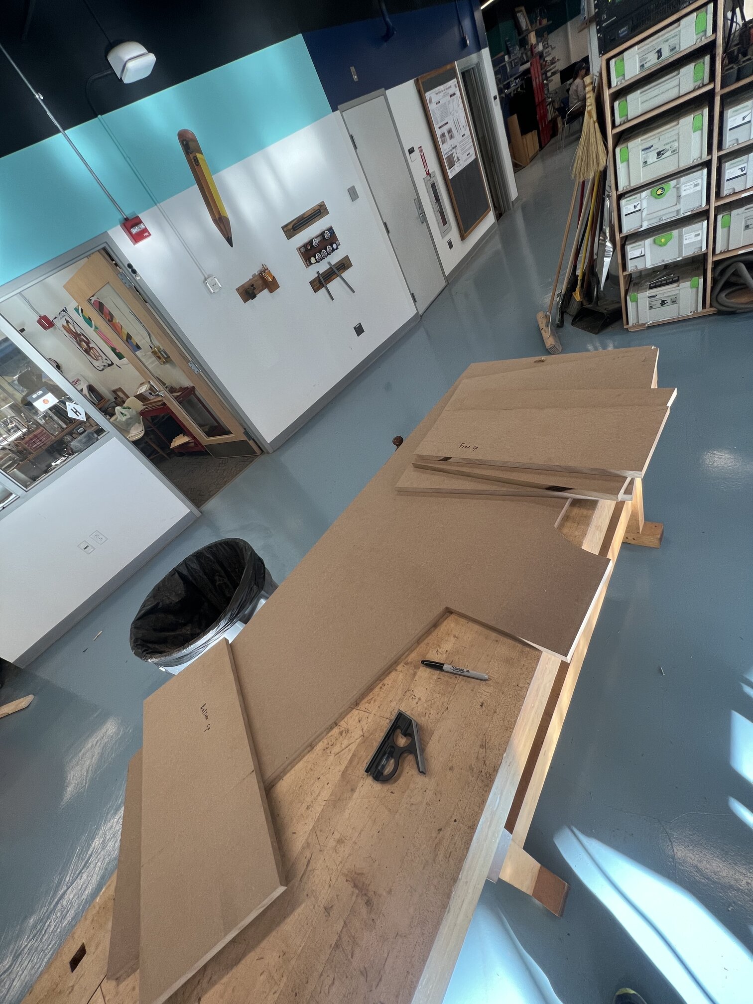
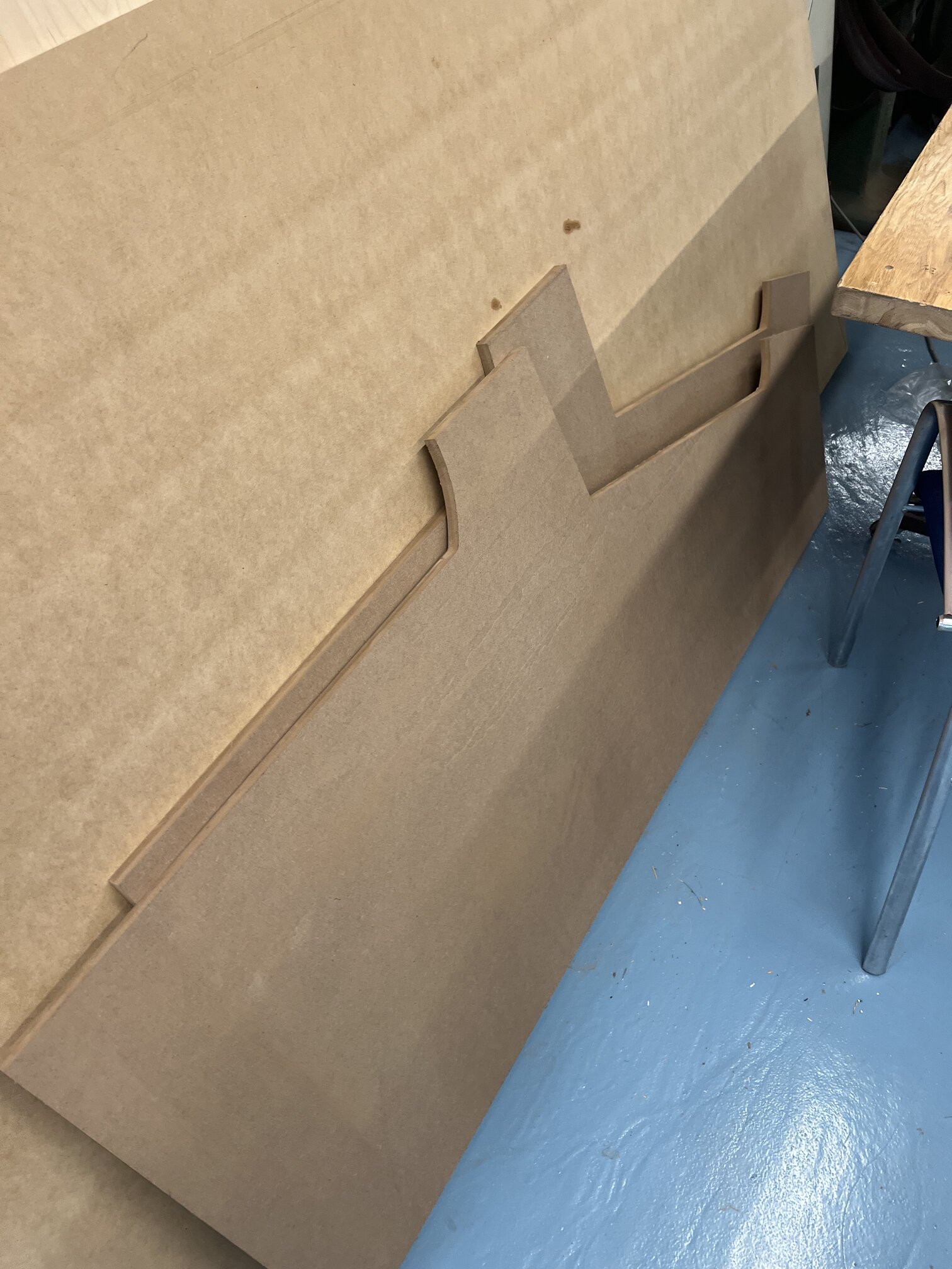
Finally! Time to CAM the body of the machine (see my make something big) for full details.
wheee something big cutting!!
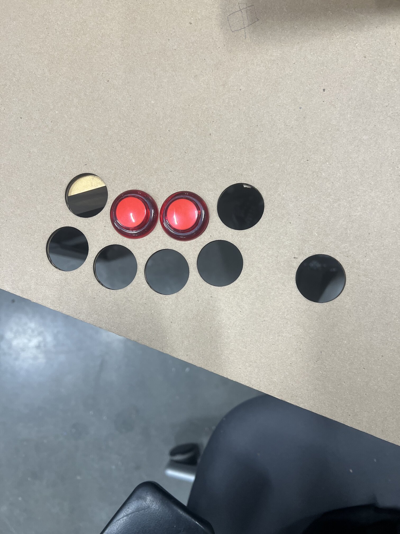
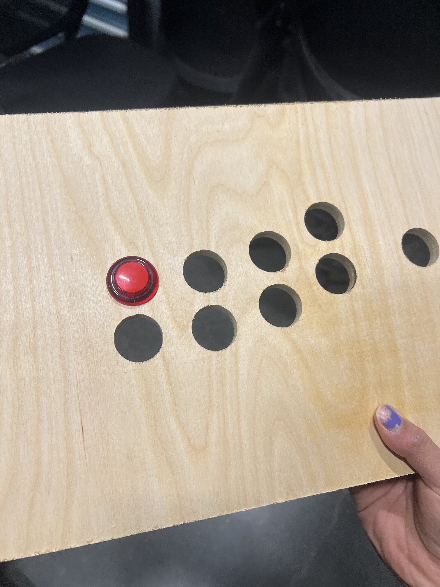
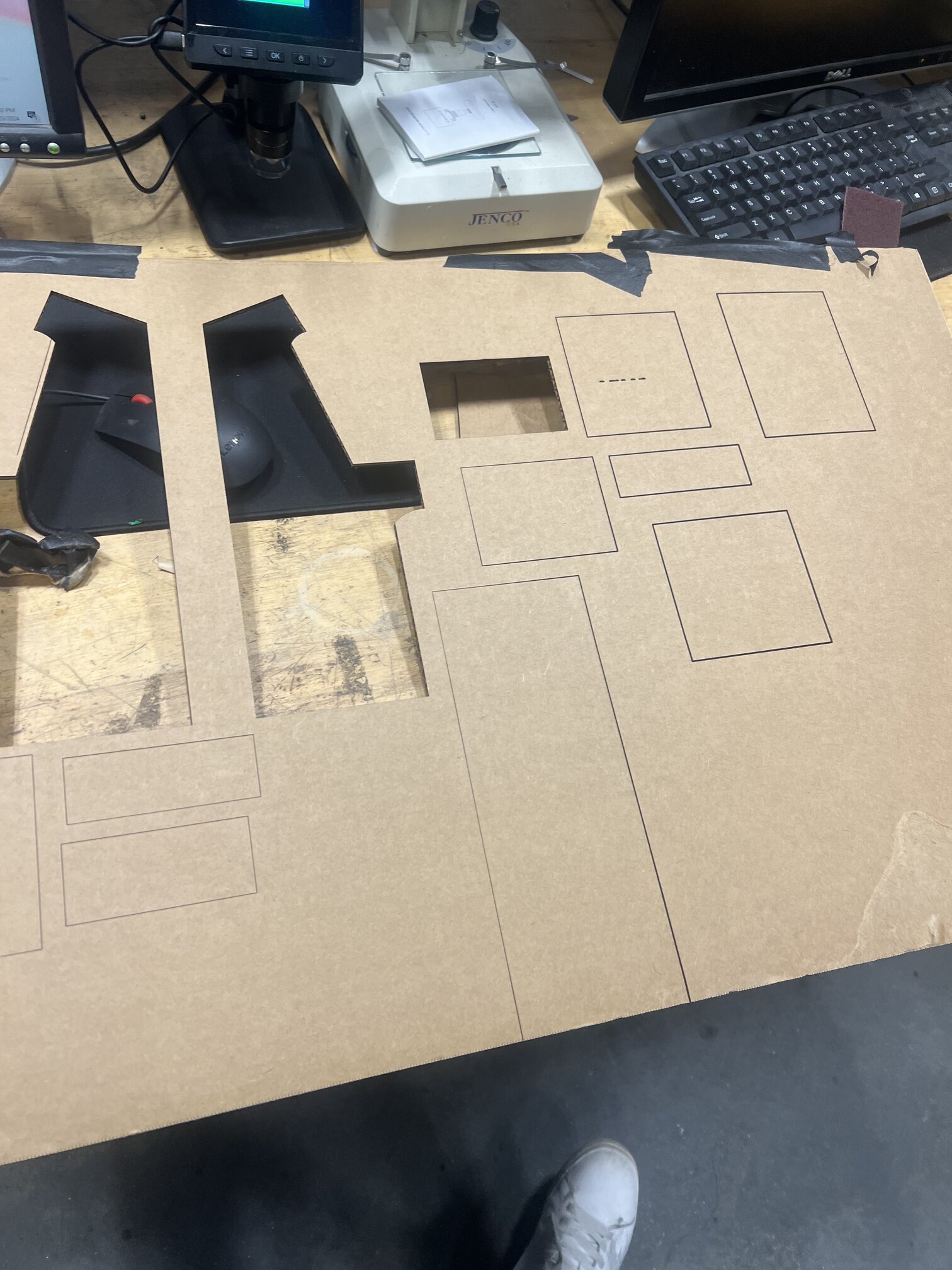
Tested my button layout on cardboard before making some minor changes:
Nov 5#
I think I found a speaker that fit what I wanted! I initially thought to have one or two small circle speakers like you might see on an actual arcade machine, driven by a microcontroller and possibly those I2S boards I used in output week. However, I realized that they can’t drive a big enough speaker for what I need - I want a LOUD speaker since this can be for a musical instrument after all. Jake told me that it would be very very very hard to make a pcb to do this on my own (“pure sound is the most hardo electrical engineering thing” - Jake), so he advised I just use a Teensy with the Audio Shield and call it a day so I can just plug it in.
I ordered it and it looks perfectly suited for the width of my machine! And even better, while it comes with a dumb remote I won’t want or need, it does have an auto-wakeup function which is super clutch for this purpose.
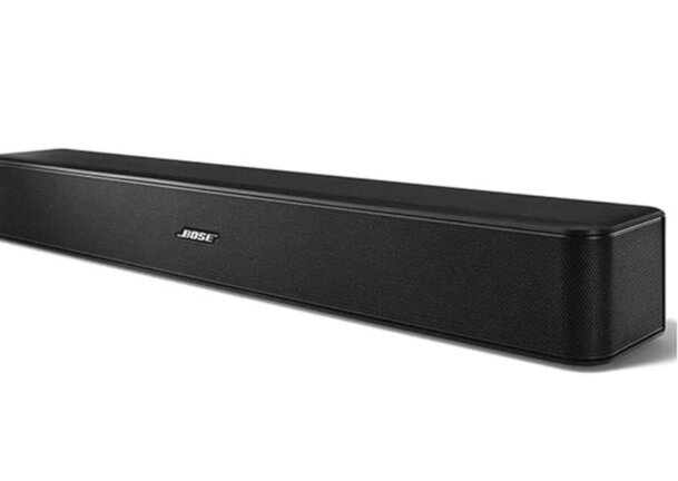
(I realized I didn’t take a picture of the plain speaker so here’s the official product pic)
Nov 3#
I updated my design and prepared for CAMing as we were trained but a few questions remain. Such as: how to cut joystick holes and speaker holes? This requires uh actually knowing what the joystick and speaker would be….
And also things like when do I paint? Before assembly/after assembly? To spraypaint or not to spraypaint? So many questions, I wish I was a mechanical engineer so I could know the answers, but the cool part of this class is figuring it out!
Oct 25#
I wired up LED matrix in a breadboard and it’s working! However the sound is very crunch - possibly due to CPU being overloaded? I am starting to think one RaspPi can’t handle all these subtasks.
In the meantime, I am glad my room is lit up like neon Christmas tree at least.
Oct 21#
Ok I realized LCD screen monitor == BORING AF - need LEDs. What I thought was low tech and hacky was actually a key part of the software who knew!
Thinking a bit more - I was pondering how I would actually install a matrix screen of some kind in a way that well integrates the microcontrollers/raspberrry pi. Stuff like this
Oct 16#
Finally I got rasp pi set up! It took a bit more than I expected because I had never used one and needed to get an SD card reader to install the OS, and find a moniter and a keyboard and whatnot so I could actually install the OS.
I realized though I like look of shiny LEDs that are a bit grainy - so thinking about both AUDIO+VISUAL library is important. I started playing around with a RGB matrix emulator and cool shaders.
Sept. 21#
Made some adjustments to CAD in prep for making model - having a bit of trouble with parameters but working on it.
Currently, my model is a bit high (~3 inches) and a bit narrow.
After fixing those thing (although params of model are pretty unstable / in flux), I made a 20% scale model and exported to try cutting.
At this point, it’s time to start ordering electronics. Immediate needs are something to control all the logic / power the screen and joystick/buttons. In the old prototype, I did use a LED array, but in this case I think I will use a Raspberry Pi with an actual monitor this time to make the screen more proper in its size. This will also give me more control of what’s going on with having to worry about voltages, etc, as well as hopefully give me a better sound synthesis engine.
Things like the dx7 are very cool to me and I will keep it in mind.
Sept. 18#
First up - scale models - both 3d printed and cardboard:
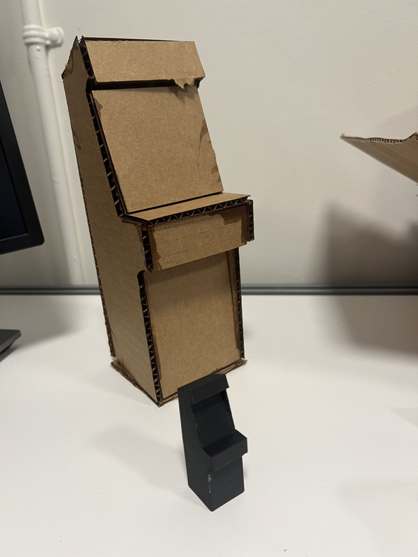
Today - I watched and read a lot of engineering content on how to actually achieve the build. I spent some time ensuring that my design was properly parameterized and thought a bit about some of the subtler details of the build - how will this be powered? How will it turn on and off? What will the monitor be? Should I laser cut or saw and etc. Next steps are to ask for some feedback on my CAD and for some electronics advice before I make a scale model.
I have a few CAD issues, but basically I think I’m at a point where I can do a small cardboard scale model to see proportions, then immediate tasks are figure out how to assemble, and electronics (screen, how to mount, etc).
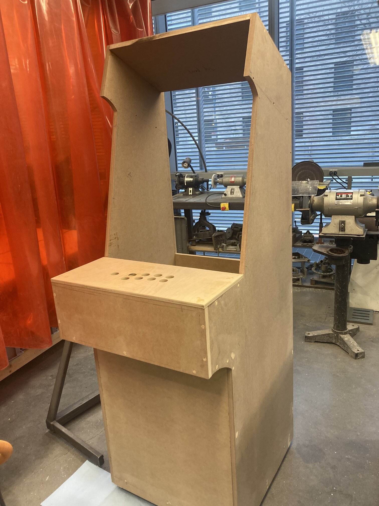
By end of construction-phase I should get it to this level - no top or back plates, but structurally intact and ready for electronics.
Learned that glue + brad nails are good option for fastening as its less visible.
The rest of the day was mostly making tweaks to my design and thinking about the questions I need to have answered before I can begin building. The most important ones are: how to fasten the inner panels, and what kind of electronics am I to use as this affects the width of the machine.
Important Considerations that I need to figure out#
material - seemingly mdf
speakers ?
transport - tiltable wheels?
how to arrange wiring scheme
marquee/lights?
doing graphics?
how to show instructions? tutorial mode?
what to make screen out of ? led? Arduino / RSP monitor? other?
volume control?
coin door?
order to paint / do decals / primer / spray paint etc
plexiglass vs acrycl for marquee
hinge back so it can open?
make it so it can fit through doorway …
t molding on edges
Sept. 14 Ideation + Inspo#
Time to find some inspiration! Looked at many many designs of arcade machines and came up with a few parameters that I thought would be important:
-simple body design is fine, but cool graphics/lights are must
-(retro) futuristic aesthetic will convey what I want musically as well
-don’t want it to be too “boxy” , large, or overall refrigerator like
I did some materials exploration, and overwhelming it seems as if MDF (medium-density fiberboard) is best bet - its not too expensive, strong, and paints well. Cons are that it tends to fall apart when wet, and is slightly less durable than plywood (more expensive).
Acrylic is very common for marquee (top bit) and a few other things, although plexiglass comes up sometimes too. Will need to do a bit more research on which to use.
I found this historical account/description of the various types of arcade machine shapes over time and brands, which was very helpful in seeing what I liked:
https://retromash.com/2016/02/09/building-a-home-arcade-machine-part-3-cabinet-design/
Atari cabinets (above) seem very boxy to me personally, but I do like “Quantum” in particular. Generally, I don’t want it to be too long, or have any huge overhangs because I think they are not nice looking :)
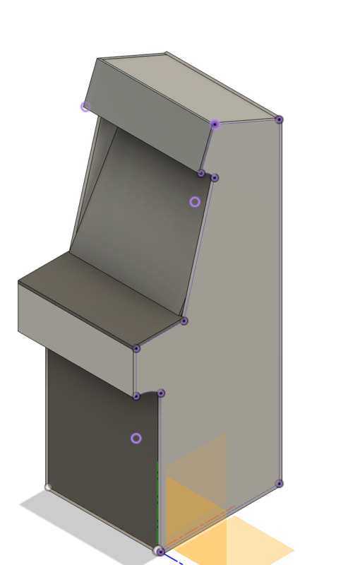
To end, I made a brief CAD, fighting with Fusion a bit, to demonstrate want I want my model to look like in preparation for making a cardboard scaled down model.
FILES AND LINKS OF ALL KINDS#
Last words: Dear Neil and whoever else may one day read this, thank you for teaching this wonderful class. To be honest, I was frequently mh let’s say…challenged… by this class, but I owe so much to you and the TAs for bestowing so much knowledge upon me. Thank you!!!