Week4
Week 4: CUTE DOGGIE PCB DESIGN#
tldr:
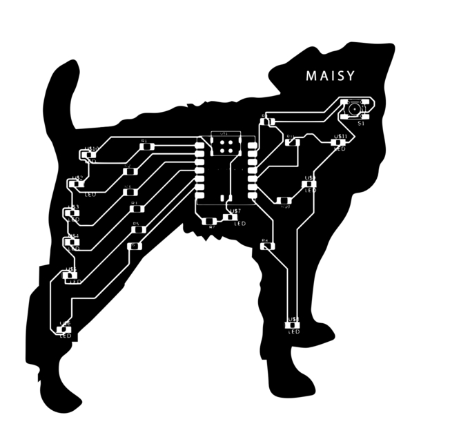
This week was slightly spooky for me as it involved something I had no experience with. Nonetheless, I found it a really cool opportunity to practice something I had never done before…
Group Assignment#
As usual Quentin gave us an excellent primer on multimeters, oscilloscope, and similar tools for testing boards - I have almost no background in using these tools so it was pretty cool to see them in action (I feel very powerful having unlocked the power to test how charged batteries are). What I gathered was the following:
Multimeters can measure a number of useful properties of a circuit or board. It has a number of ports - the most important for my purposes is the black or ground one and the main red one, which when plugged in lets you measure volts, currents, resistances, etc. There’s also a 10A plug which is used for biiig currents which I’m not anticipating dealing with. There are then the leads which you touch. Quentin showed how sometimes the leads look like cute little alligators, but some times they just look like not alligators, which is less fun, but also, I’m told, functional.
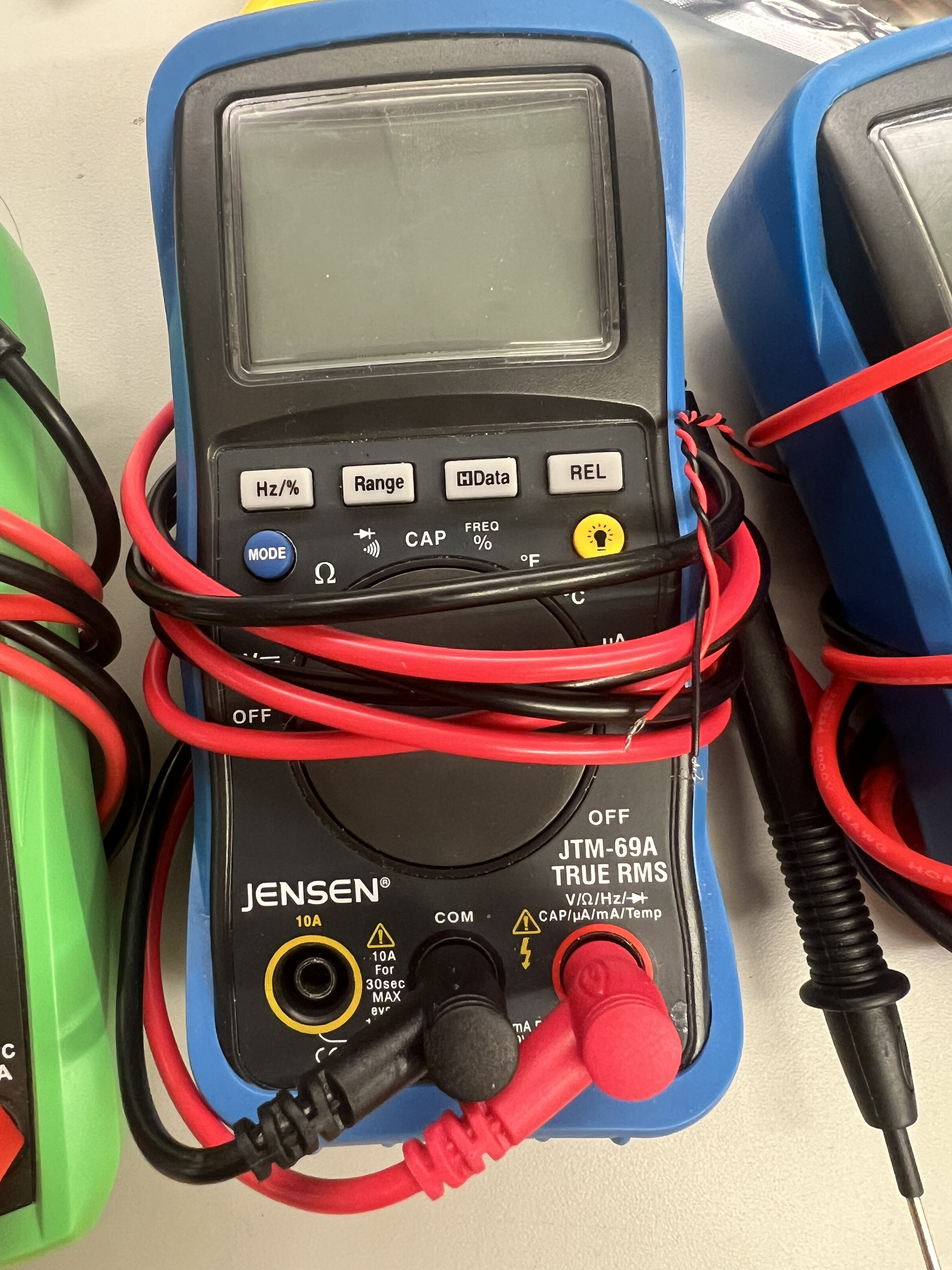
Multimeters have a little dial which let you change what your testing for - its important to note (something I didn’t know) that AC and DC have different settings, with DC looking like:
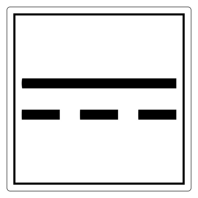


Then it is very simple to test voltage with the leads. The AC voltage looks like a ~. Another useful thing we were showed is continuity, which can tell you if two things are, as the name implies, connected, a useful property for PCB testing.
Quentin also showed us an oscilloscope. These are used to “visualize and measure electronic signals”.


BOARD DESIGN#
For the individual assignment, the first choice was which software to use. After recitation, I was very enamored with the idea of integrating everything into Fusion, mostly since I want to go as deep with a small set of tools as possible. At the same time, Quentin did attempt to strongly vouch for KiCad, and I liked the cool board design possibilities of the custom software.
I was initially quite confused, but Anthony’s recitation tutorial+ office hours helped clear things up, at least to the point where I felt like I could get started. I felt like while I know exactly what I want to do for my final project, it feels a little up in the air what the actual pcb will need to look like. This, plus the fact that I have no experience with this led me to try to make a simpler board functionally for now, but I still wanted to make it look cute. I was very much inspired by this person who made a super cool NeilBoard. So I challenged myself to make a board in the shape of my best friend’s dog, which I also vinyl cut in Week 1.

The very first step was to make a board, any board, so I messed around doing the simplest thing I could think, just a LED or two.
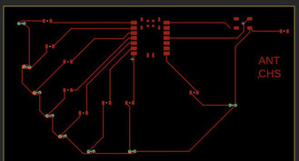
During office hours, I received a primer on some design rules I wasn’t following so well, with the golden rule I am planting in my memory being that *16 mm seems to be the magic number when it comes to clearances and trace size.
I was initially using what I was told was through hole LEDs, which I was dissuaded from using trying to use for now. For future reference, it seems the two primary options here are through-holes and surface mounts, which each have a number of pros and cons.
Basically, what I wanted was to design a board I could give as a gift where at a press of a button PCBDoggie would make cool light show - so I wanted as many LEDs as I could fit. My brain’s first thought was to reuse each digital pin multiple times by having a bunch of lights in series. This exposes my poor background with EE stuff because I was told that this would likely not work due to the voltage requirement to do something like this, especially if the LEDs were RGB or something. I then took this as an opportunity to learn more about series and parallel circuits because I frankly and somewhat embarrassingly had to ask some very silly questions about them in office hours.
This resource had really good pointers, with the key takeaways for me being:
Series#
“-The same current flows through each LED -The total voltage of the circuit is the sum of the voltages across each LED -If one LED fails, the entire circuit won’t work -Series circuits are easier to wire and troubleshoot -Varying voltages across each LED is okay” “This means you have to supply, at minimum, the sum of the forward voltages of each LED”
Parallel#
“The voltage across each LED is the same The total current is the sum of currents through each LED The total output current is shared through each parallel string Exact voltages are required in each parallel string to help avoid current hogging”
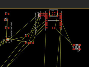
I initially wanted lots of RGB LEDs in parallel but I was having a really hard time with the routing, especially when it came to routing shared grounds / power sources that go across the chip from one digital pin to something like 3.3V:
Finally, after scaling back my design a bit, I got an arrangement I liked, while keeping the image open in Illustrator so I could roughly see how it needed to be scaled. I did a few tries of exporting my image and attempting to paste it over to see what I needed to change.
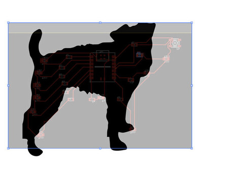
Finally I got a version I was happy with, and added Maisy’s name as she deserves :)

Here’s a few (some very basic) questions I was wondering all week that were clarified for me in office hours:
Q: wait why are we putting Xiao rp2040s on the pcb I thought the idea was to work directly with the chip?
A: we can/will move to just the chip later, but its easier to do this for now, and move to the chip alone if you need to (which not everyone will).

Q: Why not just solder on a board? Why bother will all of this?
A: Not only is milling and pcb design a good skill to know, the primary benefit is that it eliminates wires. This allows pcb components to basically last forever - even soldered boards will likely stop working after a few years.

Q: Wait why am I using digital pins to power my LEDs, why not just use 3.3 or 5V pin?
A: You could, but then you wouldn't be able to turn the lights off. Digital pins can send a voltage through the lights but also turn them off as you desire in code.
and as always…
NOTES FOR FUTURE / PROGENY#
-office hours remain more critical in this class than almost any other I’ve taken before because the TAs are all so helpful
-learning concepts is good but make sure you split your time between theory and practice to be around 40/60 or 30/70 - you can always learn the theory and intuition later but you need hands on time with the tools to make things actually work.
Link to Fusion file