Week7
WEEK 7 INPUT DEVICES: *touch touch* is this thing on?#
This week was slightly weird for me to conceptualize - it was rather low level and was one of the more confusing weeks to understand. Rather than develop some uber super cool idea which does or does not actually work, I decided to make something simpler that satisfied the assignment and focusing on understanding the material and practicing some skills (pcb making, soldering, etc).
First up was the…
TRAINING WITH ANTHONY#
Anthony being the goat of goats as usual held a bonus recitation on advanced soldering techniques which is super helpful for absolutely terrible solderers (actually a real word apparently?) like myself…
We talked about techniques like reflow, using a solder paste, and general tips on soldering in general.
Reflow soldering is when you place solder paste on the board using some method (solder paste syringe, and with or without a stencil), place your components, and then heat the board, allowing the solder to flow along the traces before cooling and making nice joints.
In theory this is really good for super small components but some people find it easier to do in general. Will I be one of those people? Time will tell…
One of the fundamental steps I think I was missing before was that its quite important to tin the tip of the iron- the purpose of doing this as I understand is to make the tip more conductive and therefore make this process easier and faster. Another tip was that Anthony suggested I solder at hotter temperatures - around 850 degrees fahrenheit or so, which is even more important if you’re using lead free solder which has a higher melting point. One more helpful thing was to make sure I’m touching iron to both surfaces I’m trying to join, adding solder (just a little), then removing the solder, then removing the iron in that order.
Some helpful Youtube tutorials were this and this (I know I’m linking to out of repo please dont smite me Neil theyre really good resources i promise)
It’s come up a bit now, so I also spent some time researching the pros and cons of
LEAD FREE VS LEADED SOLDER#
Leaded solder melts at a lower temperature, seemingly makes better joints, and is also cheaper. However, it’s most certainly worse for the environment and also most certainly worse for you. Solder fumes (actually, apparently its the flux that’s most’s dangerous according to sources like this) can cause asthma and other not fun conditions. So basically, takeaway is leaded solder is easier to use but worse for everyone so I might as well git gud and use lead free now I figure.
GROUP ASSIGNMENT#
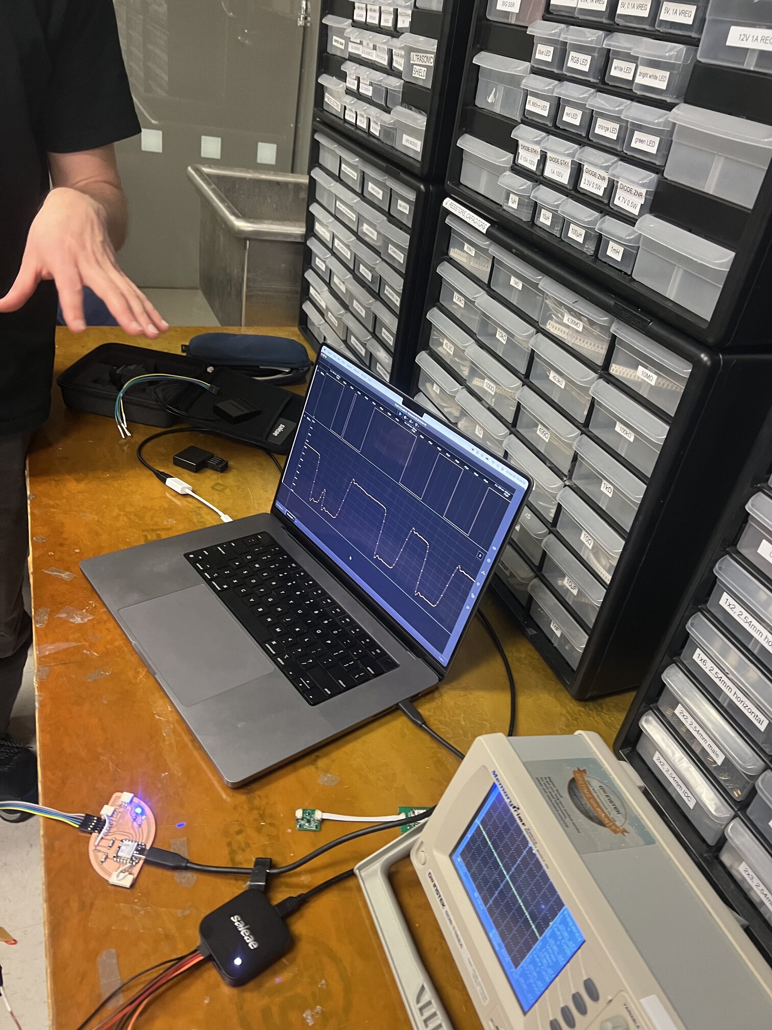
For the group assignment, we spent some time using a scope to “probe an input device’s analog levels and digital signals”. This was a bit over my head at first, but I think I have a better understanding about 1) the complexity of seemingly basic protocols like serial - seeing the bits of a basic message sent from the sensor encoded as flipped 1s and 0s that then get parsed by the hardware/software was really cool and helped me understand more.
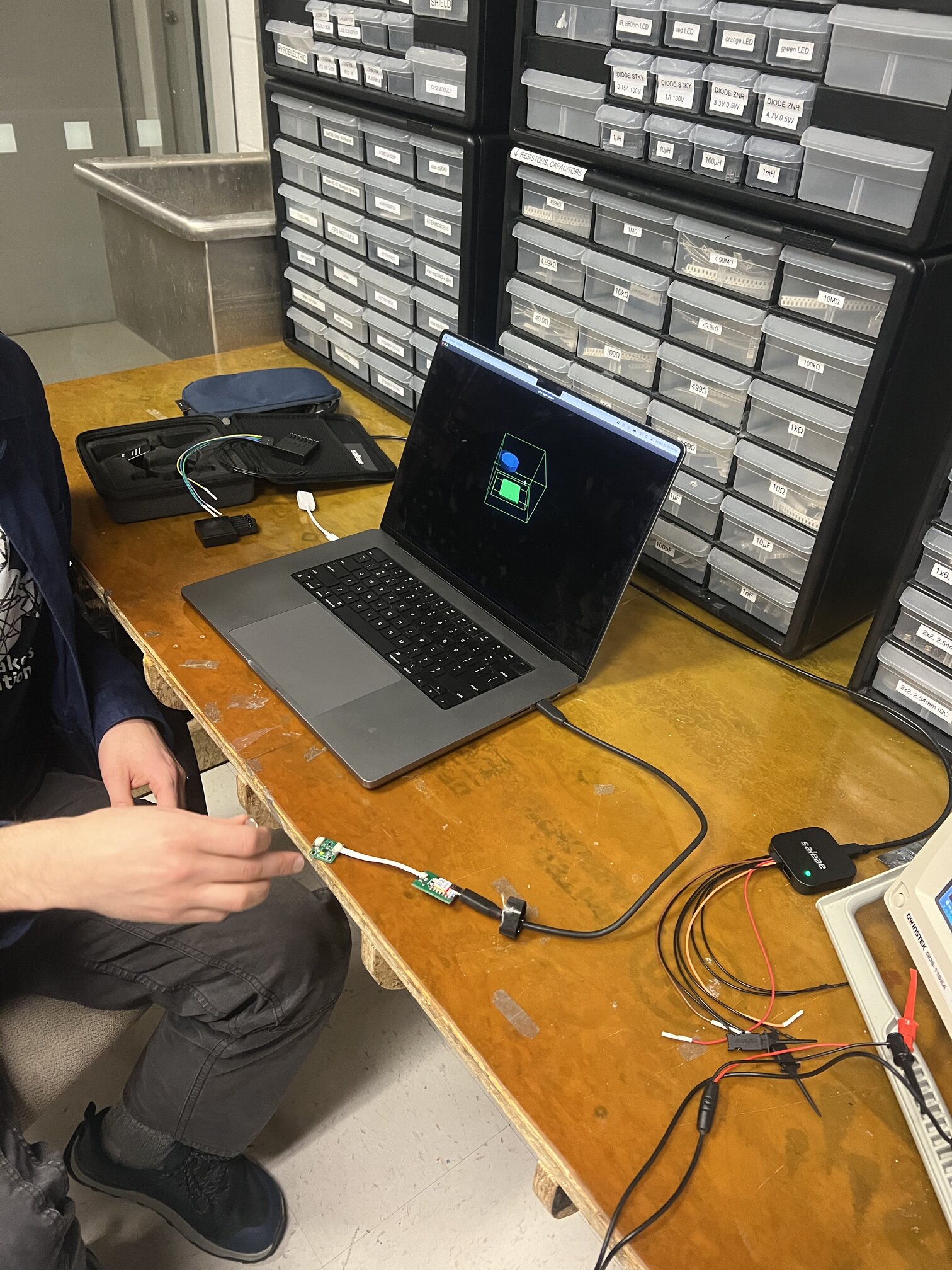


This was also where I learned some more about protocols that I’ll probably use so here goes information on
PROTOCOLS#
SERIAL#
First of all, a protocol is just a standardized way of sending info - me as a musician, I’m quite familiar with the MIDI protocol, for example.
Apparently there was once something called parallel transmission where bits would be sent to matching terminals on the receiver - now however, Serial transmission is dominant where you instead send bits one at a time, all on the same conductor. All the other main protocols I keep hearing (UART, I^2C, and SPI) are all examples of serial protocols.
Serial protocols define voltage states as bit values (like say, high =1, and low=0). From there, you need a way to sample the received bits to interpret them, and to ensure that the readings are consistent across sender and receiver (this is baud rate). You also need to know when a message is actually coming vs when its just idle. Oscilioscopes are good for decoding serial protocols!
This tutorial was really good!
I2C vs SPI vs UART#
I2C is a serial protcol that uses master-slave to send/receive data.
You only need two wires, serial clock (SCL), and serial data (SDA). Master and slaves are connected through these two lines as well as power. Each slave as a particular address that must be unique.
UART and SPI are other ways of sending info in parallel. SPI uses SCLK which is the clock but also MOSI and MISO (sadly not the soup). SPI does NOT use particular slave addresses but instead uses a chip select.
INDVIDIUAL ASSIGNMENT#
Like I said above, since this week was a bit low level and therefore confusing to me, I decided to make a simple capacitive touch board which could be augmented with musical happenings later.
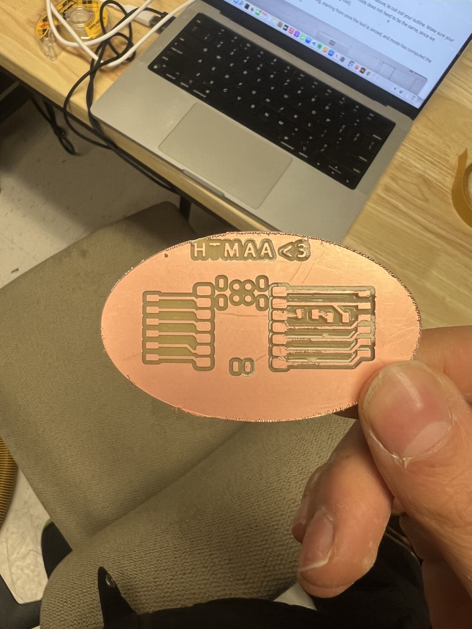
I began by making a development board for my Xiao RP2040, and like always, I wanted it to look cute so I made it shaped like a little egg:

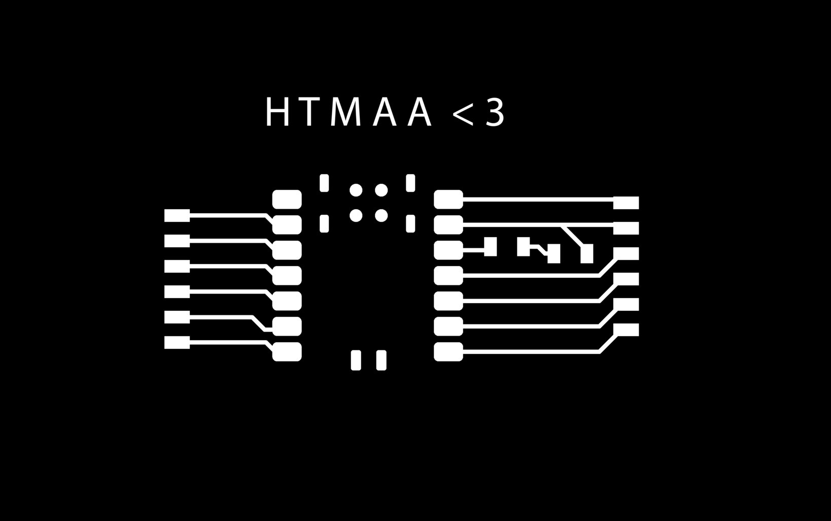
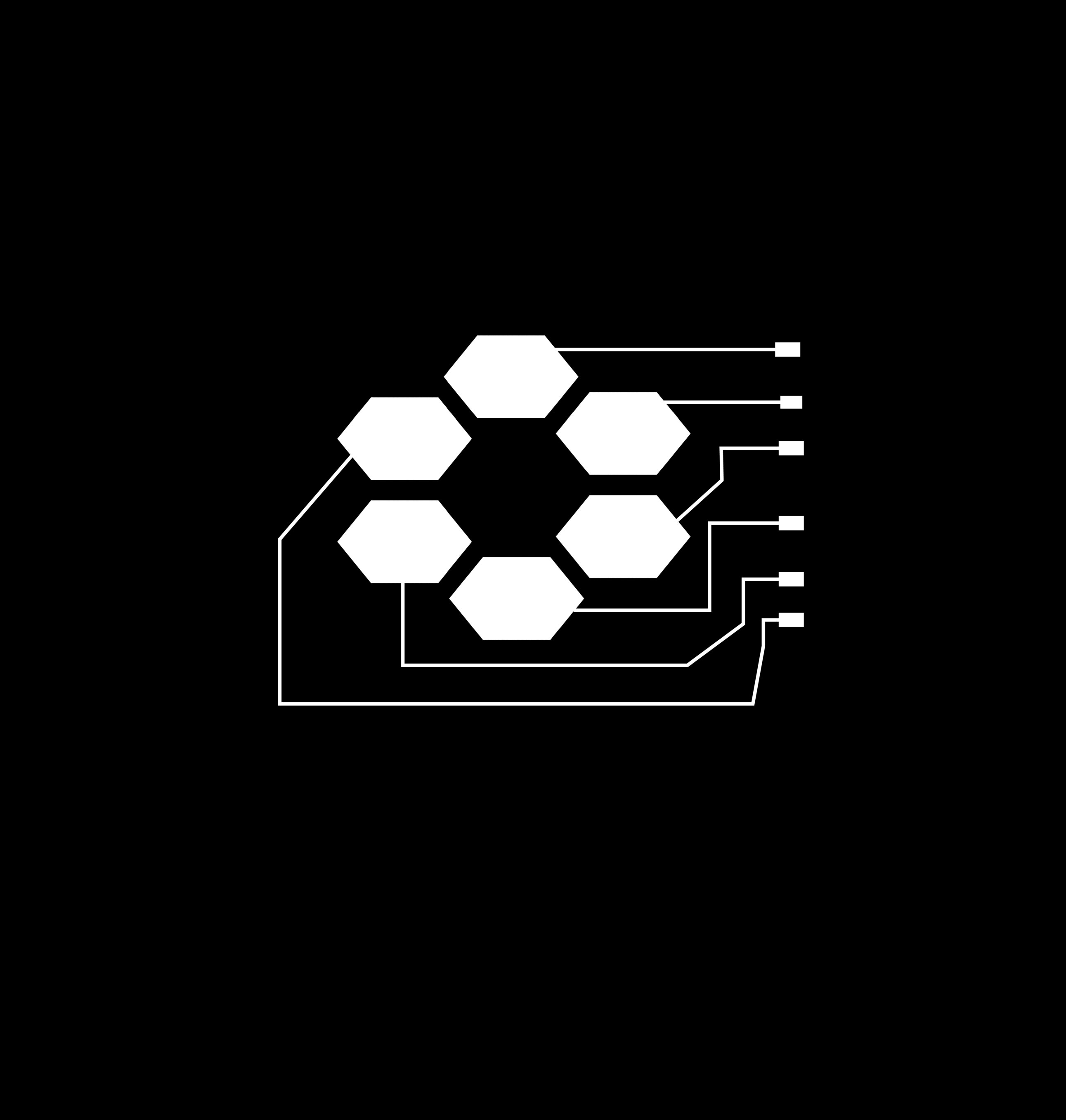
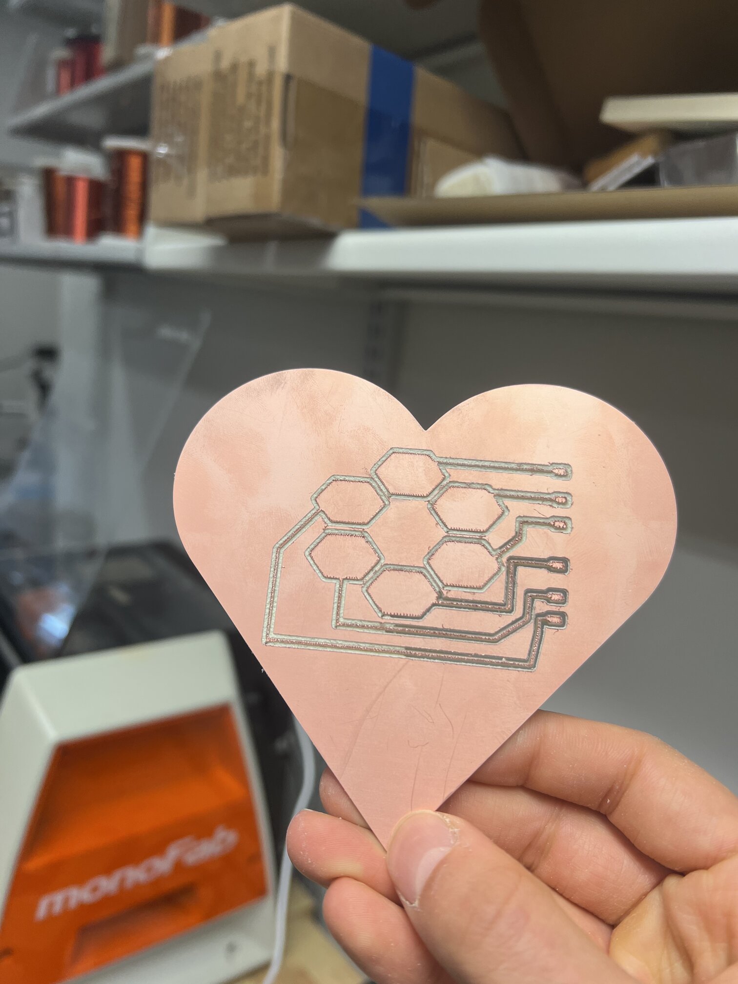
For the touch board, Fusion was not letting me make pads of any size that could be connected to traces since they weren’t actual components. I also wanted it to be cute and heart shaped. There probably is a normal person way to do this but me being me I decided at this point to totally raw dog it and draw my board entirely in Illustrator:

Now came time to mill. Sadly, the glorious Carvera broke down over the weekend under the weight of saving all of the CBA section from doing manual labour like tool changes.
Kye and I then decided to use the other, less good, but actually still kinda cool Roland SRM-20.
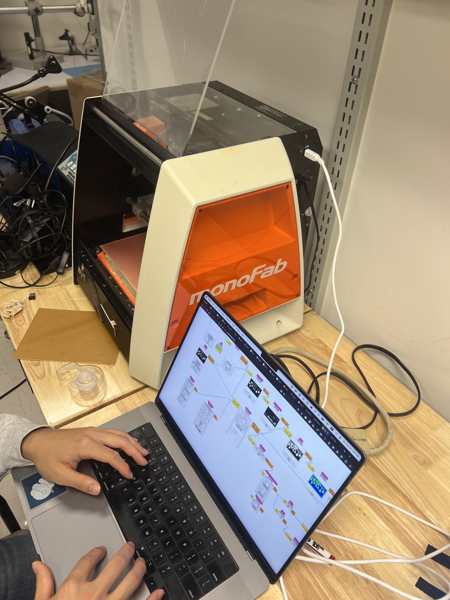
We had to do gasp manual tool changes and self-zeroing, but I kinda needed the practice. Plus now I have an appreciation for the amazing and wonderful Carvera which deserves infinite love and admiration.
The boards came out pretty well, except even though I was pretty sure I measured my traces in Illustrator, they were a bit thin, which combined with the fact that the copper must have been a bit bowed and the machine went a bit deep, meant that some of the spaces between the traces was totally eaten away and the traces themselves were very fuzzy, which was actually leading to shorts until I cleaned it up.
SOLDERING….#
After last week, I was mildly traumatized by soldering so I was scared but armed with Anthony’s new pro-tips, as well as solder paste and thinner tips, it actually went a bit better this time!
I tried solder paste at first but I found it kind of messy to work with and caused a bunch of shorts that I spent a while wicking up. I also made a fatal flaw of not immediately taping the bottom of my Xiao. This combination of things I suspect made it so when I plugged it in for the first time, it lit up in a blaze of glory and I rejoiced before it promptly shut off and never turned on again :((( I think there was a short somewhere that killed it :(((
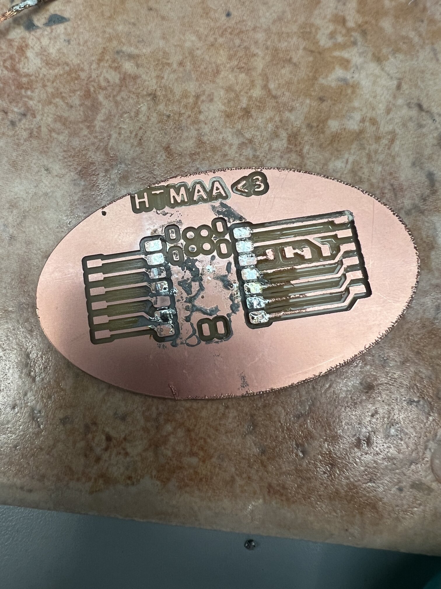
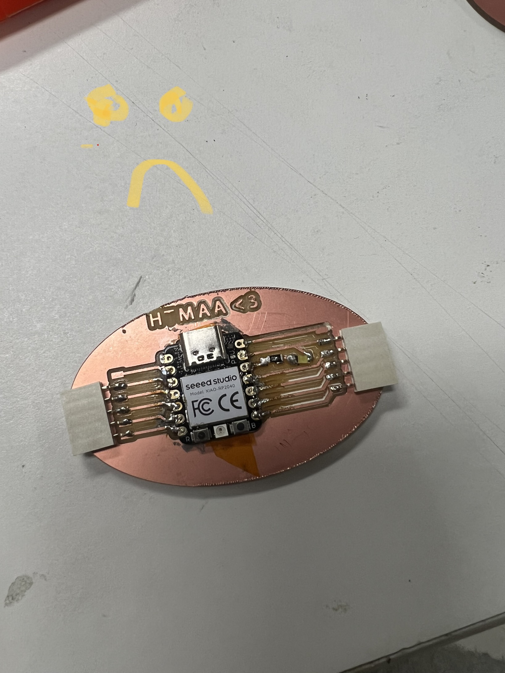
Welp one Xiao down, I prepared to tried again, only for Quentin to tell me at Office hours that only microcontrollers with built in touch libraries can get away with a circuit like mine without resistors. So faced with the prospect of redesigining or simply getting a new microcontroller that would in fact make my board work, I took the easy route of switching to the Xiao SAMD21 (especially given that I needed a new microcontroller anyway :) ).
Then, using the built in library provided by Neil, I wired everything up and it worked!
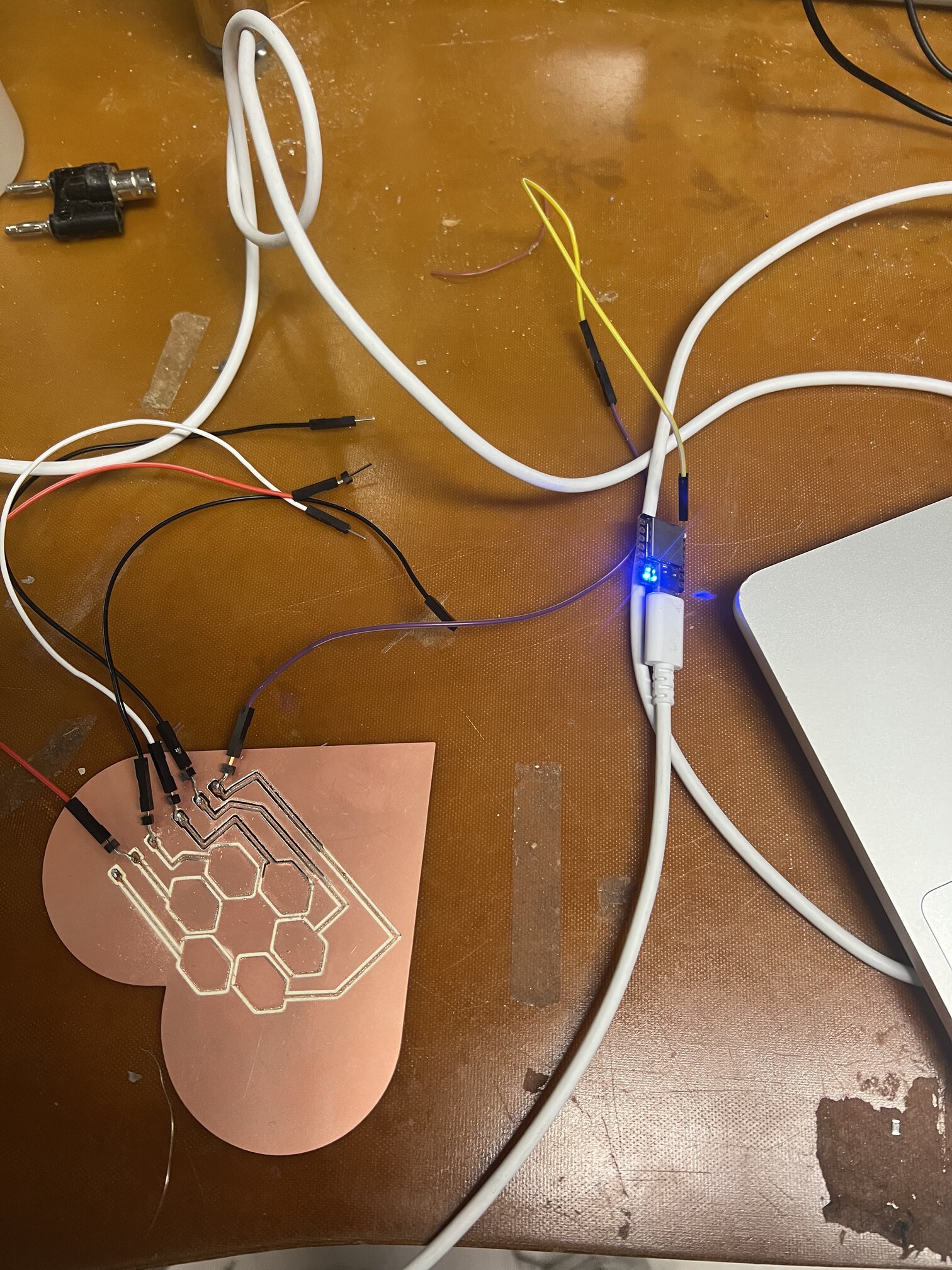
I didn’t really understand why it worked, so I spent a little time researching what wizardry makes this capacitive touch thing function. The very simple answer is that the presence of something like a finger changes the capacitance value e.g how much charged is stored, which when read using analog reads and a few other things can allow one to in essence detect when a touch has ocurred. Cool stuff.
A FEW QUESTIONS THAT I STILL AM WONDERING THAT I WILL GET ANSWERS TO TODO#
Q: How do I begin parsing big scary low level pcb diagrams? I don't really know where to begin in understanding them?


Q: Why bother with all this low level code / using the microcontroller with no board when I have something like a Xiao? What can I do with them that I can't with a Xiao?


Q: What is the ground pin actually doing? How does it function internally?


Q: What is FTDI and why I do see it everywhere? The internet says its a company for making parts?
NOTES FOR PROGENY#
-starting with something you feel confident in being able to do and expanding from there leads to much greater odds for success than instantly gunning for the moon
Dev board Illustrator file Capacitive touch board
<3
