Week8
WEEK 8 OUTPUT DEVICES: oh right i make sounds#
This week was hopefully the final saga in the “Antonis trains himself to not suck at soldering” Homeric epic. So once again, I took on a relatively simple project but really tried to practice a ton. Despite the simplicity of the output, I think I was in the shop every single day for hours practicing my soldering, milling boards, etc etc.
tldr: little baby speaker death metal <3
GROUP ASSIGNMENT: POWER WITH ERIK (thank u again for training me erik)#
I was traveling and had to miss the main group assignment session, so Erik in an extremely goated move gave a bonus one to me and Jessica. The assignment was to “measure the power consumption of an output device”, which I initially had no idea what was meant by that but actually came away with a much deeper understanding of power than before.
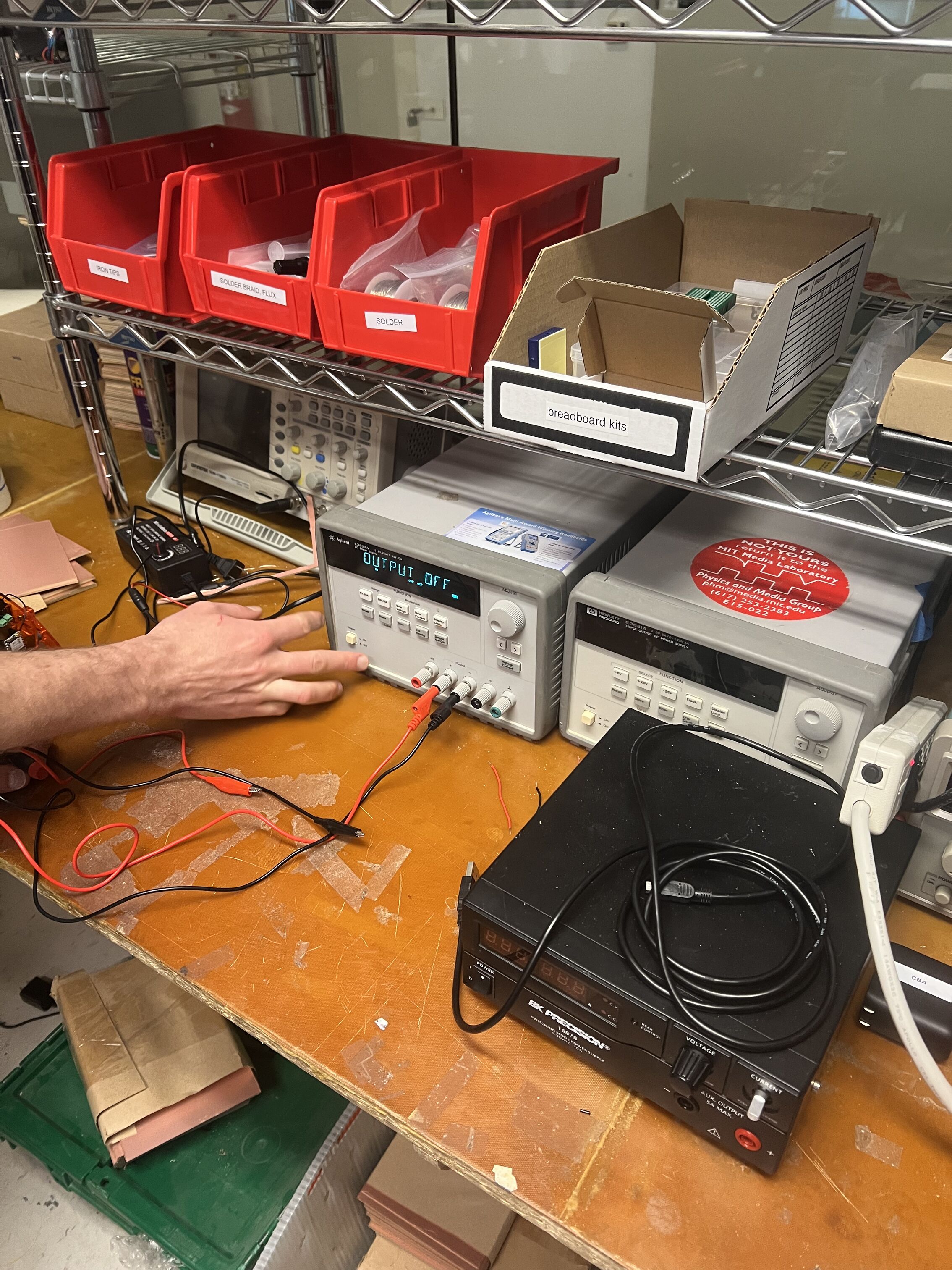
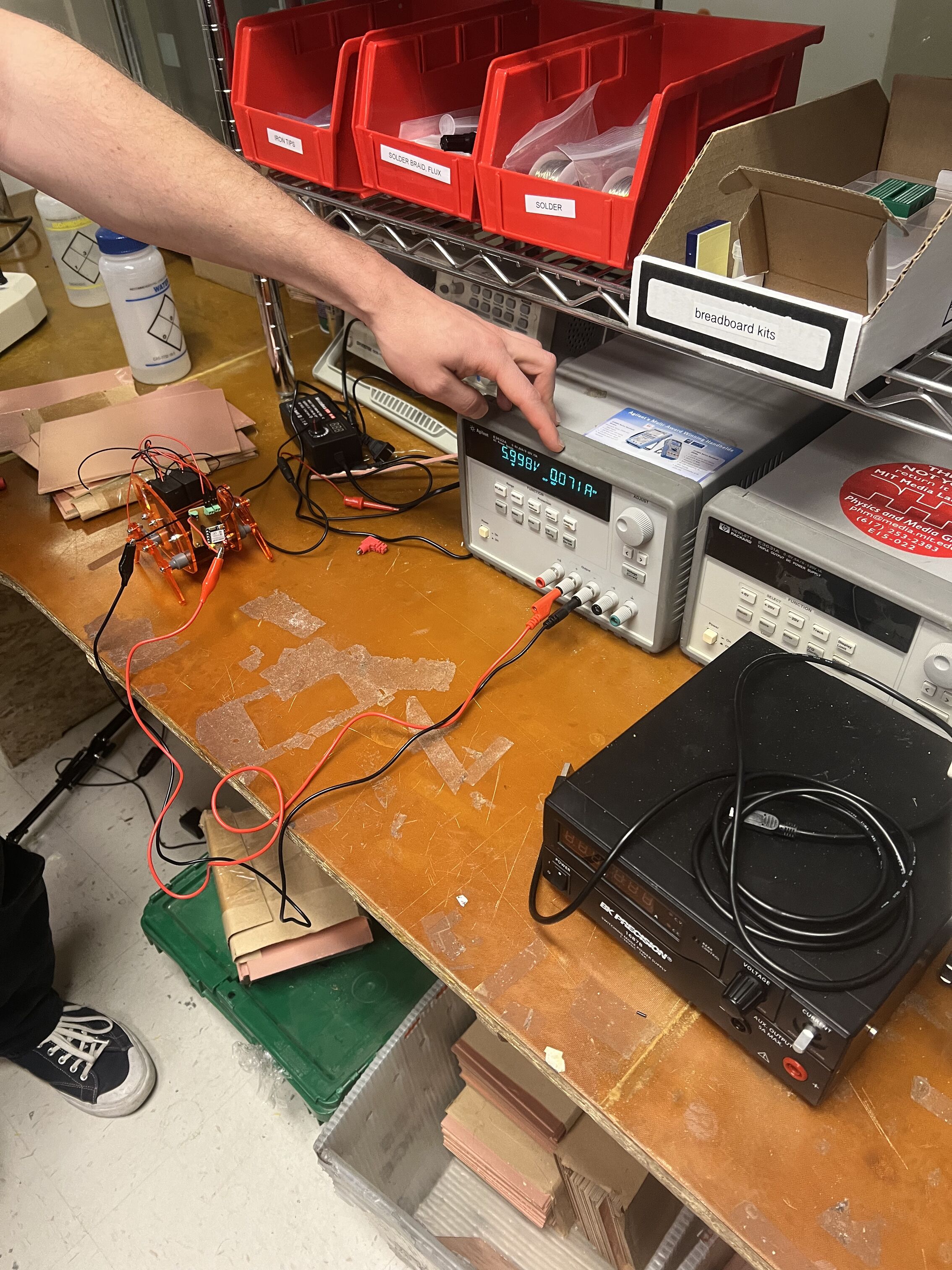
We used a power supply to first, power a thing (in this case, a silly little walking robot made by Marcello), and then measure the actual current needs drawn by the thing - very useful for things like designing batteries into your builds.
Basically, power (measured in Watts), is a “measurement of energy transfer over time”. Its a rate - a helpful analogy in the source above was thinking of it like lifting a weight - doing the same motion faster requires more power despite the energy being the same. It’s calculated using the equation P = V*I. Of course, power isn’t consumed since energy isn’t created or destroyed - in our case, power usage gets turned into heat (which is important so you dont make a big fire and burn down the CBA shop).
Using the power supply, given any voltage you have flow through it you can then see the current requirement and so calculate the power. Something that was important for me to note is that generally the voltage requirement is fixed depending on what you’re trying to power, but the current demands can fluctuate, so its good to be able to observe what is needed when.
So using this we could easily see the power output of the little robot.
INDIVIDUAL ASSIGNMENT: OUTPUT DEVICES: a once and future GameBoy#
My big idea that I want to work towards as perhaps a side project was inspired by other final projects of HTMAA’s past. Basically as a lover of old 8 bit music and specifically Pokemon, I want to work towards making my own GameBoy from scratch.
With that in mind, I set out to play with all the output devices (and some of the input devices) I would need to make this happen. Given all my practice and my tears with soldering, I was slightly intimidated but ready to synthesize what I learned and MAKE 👏 SOME 👏 STUFF.
First step was Wokwi messing around with touch screens, although I didn’t stay there very long:
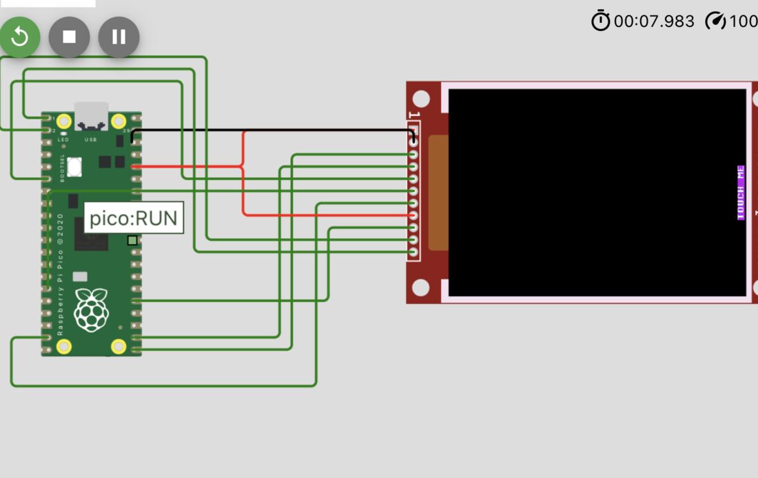
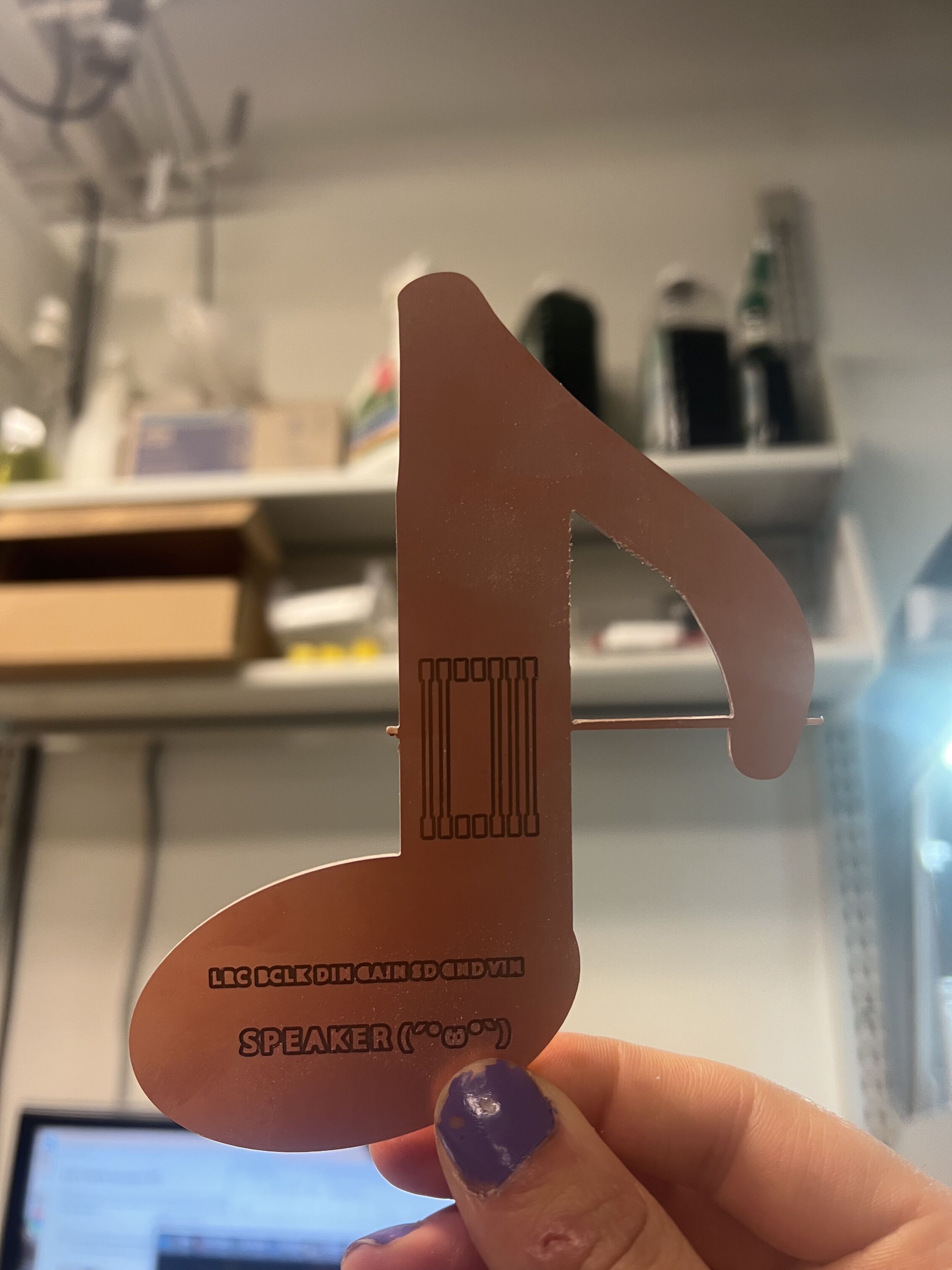
I figured for this system I’d need three boards: one for the buttons, one for the Pi Pico breakout, and one for the screen. I realized eventually this left no room for the speaker, so in a future iteration I’ll probably combine the speaker onto the breakout or something. For this week though, I just made the speaker have its own board. So I designed and milled them - there were a few failures though due to traces not cutting / endmills breaking / general sadness, but we found a way and the boards came through.
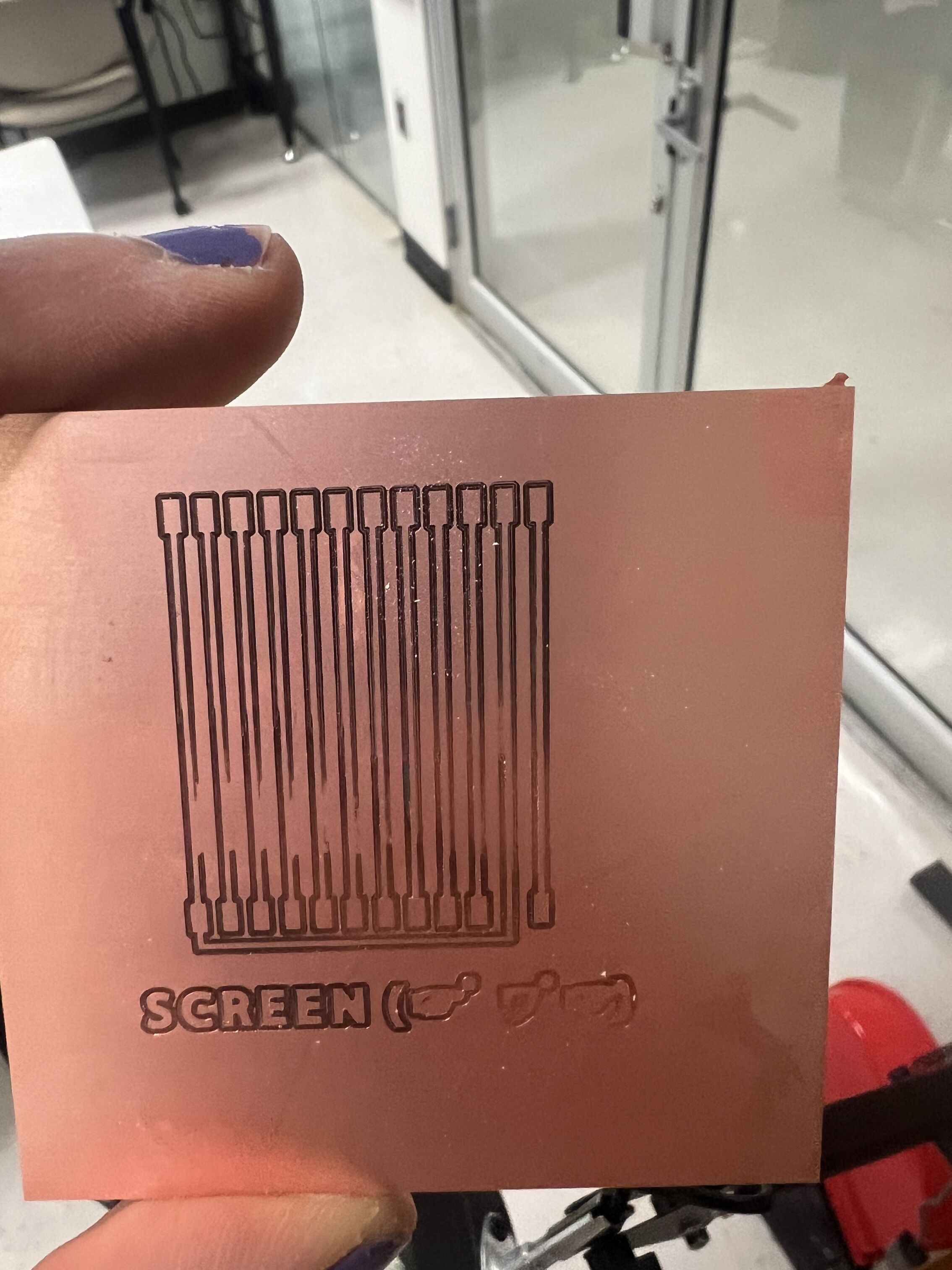
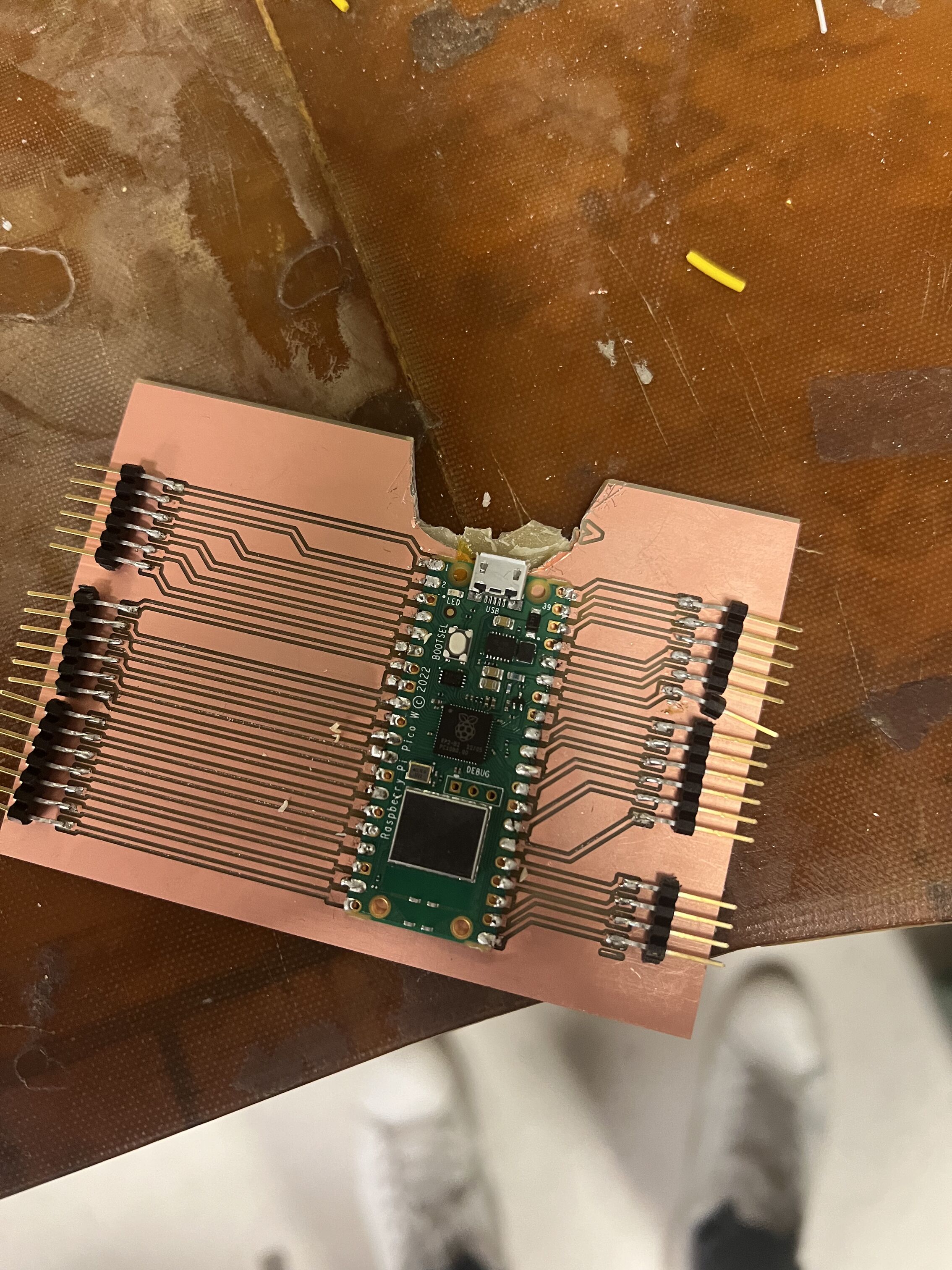
I then started soldering which actually was far less painful than it was before!!! Progress!!! I still suck and it takes me a long time but I am now pretty confident in my ability to solder non super tiny components - progress!!!
I then tried to plugin my Pico only to realize that it takes a micro usb which I did not have. A few borrowed/stolen cables later (which I returned promptly), I then realized that the big chonky micro usb cable would simply not reach the port given the cutout of my board. So very sadly I took some cutters and did some intense and brutal surgery to make it fit:
After this, I soldered my audio board. The one scuffed thing here was that I couldn’t find a screwdriver to loosen the terminal block so I just soldered it directly to the pins. But hey, more soldering practice I suppose. Naturally, the board that makes sound is shaped like a music note because we love symbolic representations of physical phenomenon now don’t we.
After all this, I decided to try CircuitPython for the first time because it had a i2s library I could use to make using the amplifier much easier. I spent a little bit of time figuring out the workflow and how to actually send code to the board, but got it working soon enough. At first, nothing was happening and I realized this was because I had downloaded the Pi PICO not the PICO W’s CircuitPython which was different enough to break things.
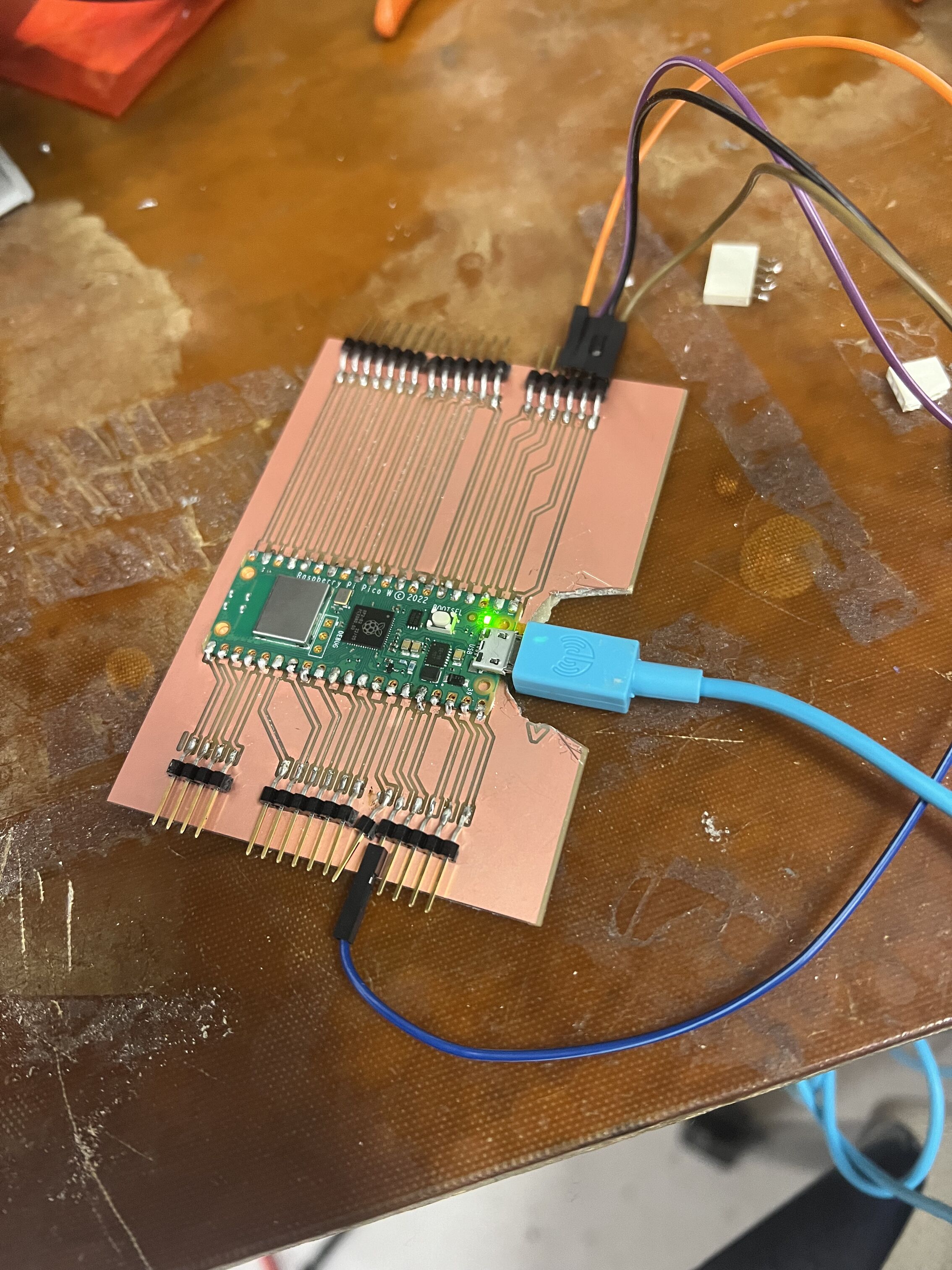
The workflow was a tad cumbersome at first but I like it!
Then, I connected everything, and….it didn’t work….. I used a multimeter and discovered that a few of the headers had gone slightly airborn and weren’t actually connected. Also, it appeared that literally some of the male headers weren’t pushed in far enough which also made me sad. So after fixing this things…it worked!!! which made me very happy. There’s like no room on the Pico itself for much music at all, but I did try some little fragments of music like my usual sound check Doom music, and one of my favorite pieces of all time the Threnody to the Victims of Hiroshima. It was really clicky though, perhaps because I attempted to make it smaller which may have scrambled some things.
BONUS OUTPUT DEVICES#
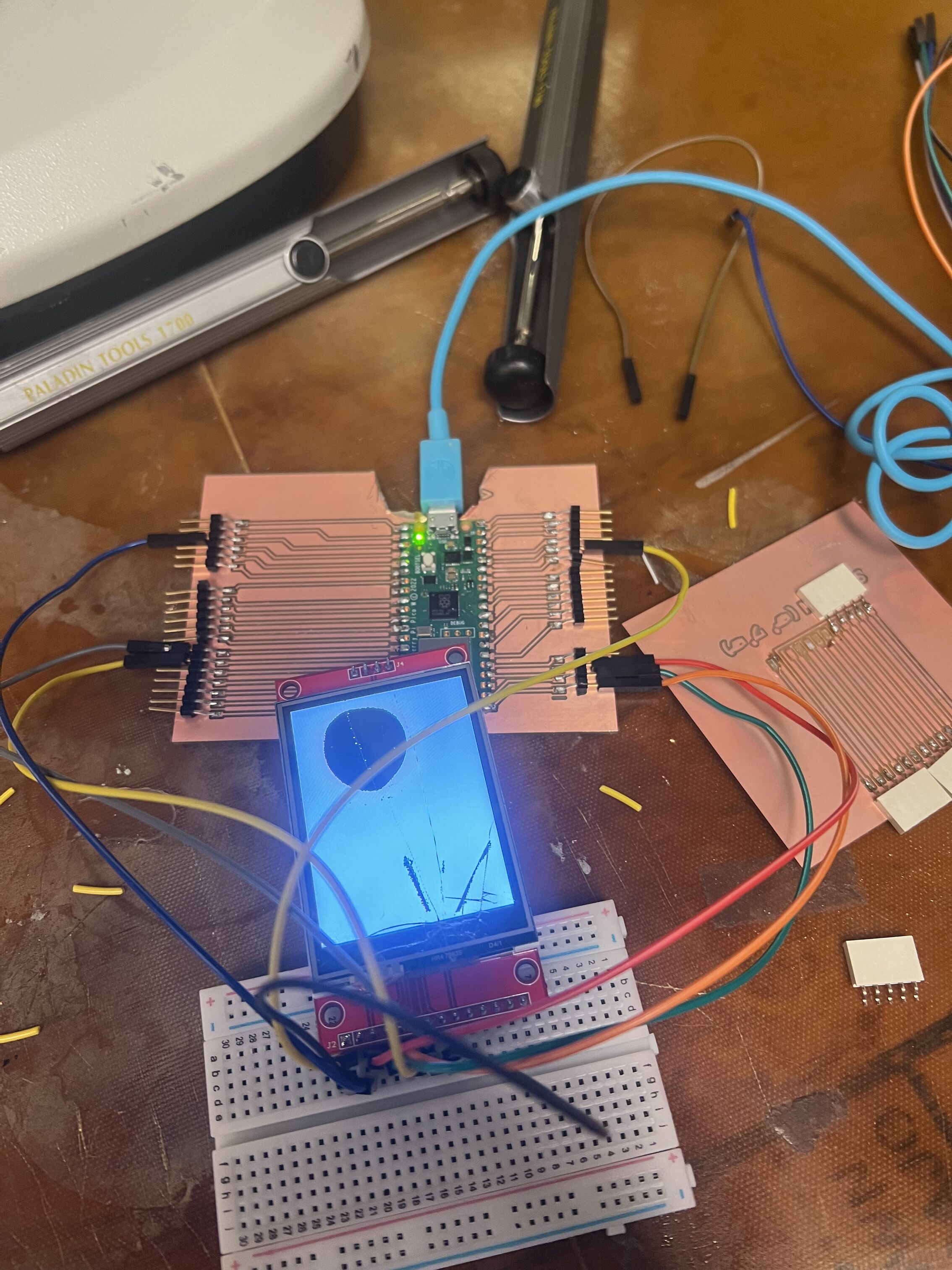
I then spent a little time messing around with a few other output devices, namely regular displays and TFT touch displays. I was in a bit of a rush and did a super janky direct solder job but it worked well enough, and was a good time for me to refresh and compare my knowledge of I2C. The TFT touch screen, an SPI device, had more pins, especially given that I want to use the SD card function. I wired it up (using a breadboard to test for now) only to very sadly discover that the screen was cracked and I suspect something internally broken because it only lit up a portion of the screen and nothing else :( - oh well next time!

QUESTIONS THAT I WAS WONDERING THAT I GOT ANSWERS TO EVENTUALLY#
Q: What's a logic level? And by extension a level shifter?? Why do we need those
A: Yup, different microcontrollers have different logic levels (usually 3.3 or 5V). You have to be careful because sending the wrong level could wreck a component, potentially requiring a level shifter of some kind to get the voltage to a safe level.


Q: What is PWM?
A: Basically a way of turning a signal on or off at some rate. You can specify the duty cycle which basically states what percent of time the signal is on. Our digital pins are basically PWM pins.

Q: What is I2S?
A: Basically yet another protocol, this time for transmitting sound.

Q: Pi Pico vs Pi Pico W?
A: W has wifi capabilities. There are a few smaller differences,but that's really the main one.
NOTES FOR PROGENY#
-think very careful about how modular boards will connect - things like shared pins and excessive wires flying about can really add complexity and mess you up!
-soldering really is a skill, it takes practice, start simple and you will improve