
*Please note, this project has now been significantly updated. The below relates to the initial prototype created during HTMAA. For a more up to date picture please consult this paper and my personal website
My final project for HTMAA 2024 is the Anemoia Device: a synthetic memory generator that uses generative AI to provoke nostalgia for a time you have never experienced
The word anemoia means feeling nostalgia for a time or moment you've never experienced. I discovered it while researching memory and found the concept to be highly poetic and fitting towards my research and techno-aesthetic goals.
For me, the goal of taking How To Make Almost Anything wasn't just to learn how to make, but to combine my thinking around why and what we make (alongside if indeed we should make) while enhancing my actual abilities to materialize sometimes highly abstract concepts like anemoia.
In my research I'm exploring the connection between memory and digital data, combining technologies like synthetic biology, machine learning, and biological computing, to materialize data into tangible, poetic interactions that reimagine our relationship with digital information and living systems.
For my final project the notion of a memory generator had been percolating since the first week. However, a few things then happened which helped me to fully define the concept.
1. I began playing around more with generative AI than previously. I was amazed at how powerful it was compared to my first experiments around 2017/18. I became curious about how physical AI interfaces could facilitate the integration of simulated memories.
2. My research led me down a speculative path of generated memories, which might be considered ‘false’, however I also saw an opportunity for generated memories to promote empathy by allowing people to explore beyond their own lived experience. Working with AI in a more symbiotic way to create hybrid experiences.
3. I have been keen to explore the bridge between scent and memory for some time and the opportunity has never fully arisen. However, the above thoughts lend themselves beautifully to scent, and I began to wonder how scent might help people travel to new types of memory-experience.
My initial design idea was to use dials to take an input image and control LLM prompt generation which would lead to the creation of a ‘new memory’. I was keen to make using AI more tangible and thought seeing prompts update on the fly via dials would be interesting.

I set out to create something that could respond to these thoughts. I imagine memories that stretch from the recent to distant past, from ourselves to more than human alternate realities; to reconnect us with ourselves and the myriad of living and non-living beings.
When memories fade, can we generate hybrid memories to offer people a new kind of sensory intimacy with the unseen and the unremembered?
To create a machine that could do this I needed a reference and a metaphor. I examined historical devices such as the Antikythera Mechanism, an ancient (perhaps primordial) computing device that worked with novel technology at the time, mechanical gears, to connect us to the future of space and time. The Anemoia device then could be framed as a device working with a novel technology, generative AI, to connect us to the past of the unseen and unremembered.
The development of the project can be broken into 4 high-level parts:
The project should be capable of taking an input in the form of an image, transforming that image into a usable/decipherable text caption, and generating instructions for ‘printing’ a scent. To achieve this, the following tasks were identified:
At some point I did project management professionally, it's not something I therefore enjoy. Especially for projects like this. However, it is a necessary evil and I like to use a simple, lightweight approach that keeps me organised. To help plan, I used Notion to break everything into work streams and some individual tasks. I did not plot out everything but had some notion (pun intended) of what needed to be done by when.
Initially, I planned to use each week leading up to the final project to complete sections of the work. However, Machine week ended up being much more consuming than anticipated.
Another peculiarity was that I actually ended up finishing the Anemoia Device during Wildcard Week and then did my full Wildcard Week project in the last 48 hours of the Final Project Week. This worked better for me as my wildcard has no association with my final project and jumping into another workflow and task would have made no sense.
Another important note, particularly with the scheduling of HTMAA, is that when I was finally ready to make orders, it was Thanksgiving/black friday period, which on the one hand made things cheaper but on the other hand made delivery times extremely elongated. If you're reading this, do try to order before this period(!)
I decided to start with the part I was least confident about working (and which I assumed would cause the most problems) - the pumps. I was able to get some very powerful diaphragm pumps from Ozgun in my research group (Tangible Media Group at MIT Media Lab) and started out by simply trying to operate them. They were rated 12V, but when testing with a regulated power supply I found they were operable from 8V. In any case it seemed prudent to use a 12V power supply.
I then began researching how to safely control the pumps, with a 12v supply given that the microcontrollers I work with supply and operate at much lower voltages. Since the pumps I was planning to use are essentially DC motors, similar to what we used during machine week, I realized I need to use a relay to control the pump with my microcontroller because the pump operates at 12V and requires more current than the microcontroller can handle directly.
The relay acts as a switch that lets the microcontroller control the higher voltage and current without being directly connected, ensuring the circuit is safe. It also provides electrical isolation, protecting the microcontroller from potential damage caused by electrical noise or surges from the pump.
I ended up using commercial relays for reliability purposes. I was initially considering (and designed a board) using a smaller h-bridge component and may revisit that in the future. Even with the relays in place, it's surprisingly easy to fry your board; simply unplugging the USB-C of the XiaoESP32S3 before disconnecting the 12v power left one of my microcontrollers unusable.
To get to the final intended outcome, I went step-by-step starting with 1 pump and 1 relay with a very simple circuit on a breadboard. I gradually added complexity - increasing the number of pumps, switching to a PCB, controlling the pumps with potentiometers and web interfaces (during network week).
I designed a total of 5 boards making this project. The first 2 boards were designed to work with an H-bridge from the CBA inventory. However, as mentioned, I changed my approach to commerical relay modules in the interest of reliability. The relays have 6 pins:
Wiring was quite straightforward. VCC and GND connect to the XIAO’s pins (3.3V for the VCC worked best). IN was connected to any of the XIAO’s GPIOs. NO connected to the positive terminal of the pump and COM connected to 12V.
I used everything except NC as I wanted to ensure the pump was only activated when the relay was triggered, allowing the circuit to remain open (disconnected) by default for safety and to avoid unintended operation.
I started with a simple board, designed to house a XiaoESP32 S3, to control a single pump with surface mount connectors for a relay, connectors for a pump (through hole), and a surface-mounted jack for a 12v power supply.

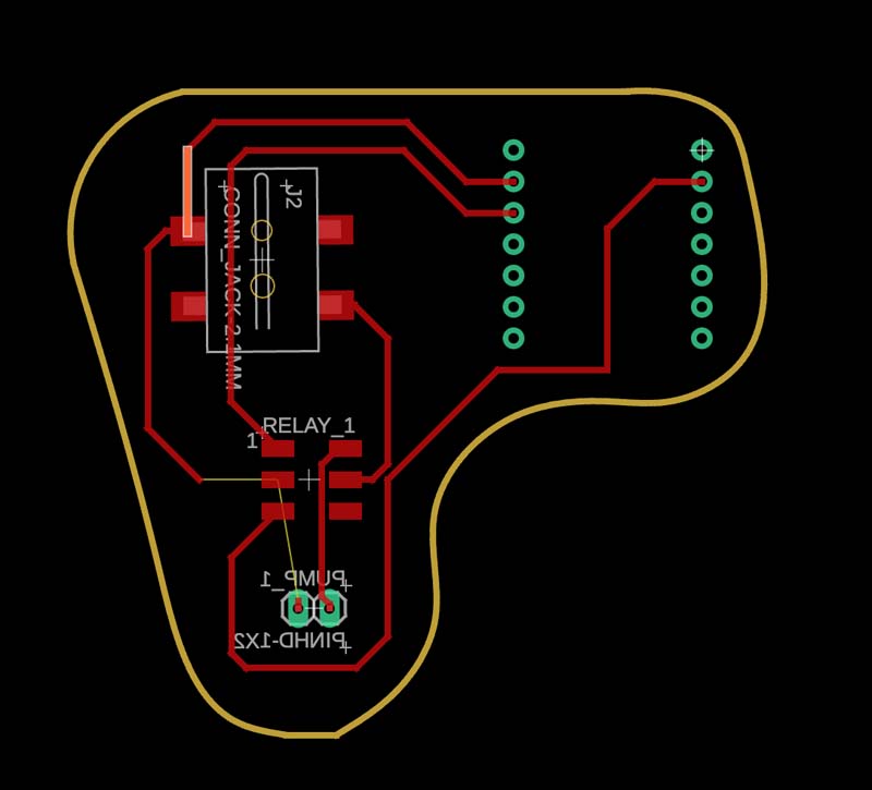
This is the relay I ended up using, which was very affordable. They are rated at 5V, which is sufficient for the XiaoESP32 microcontrollers I was using. I decided to run jumper cables to surface mounted male header pins for the relays.
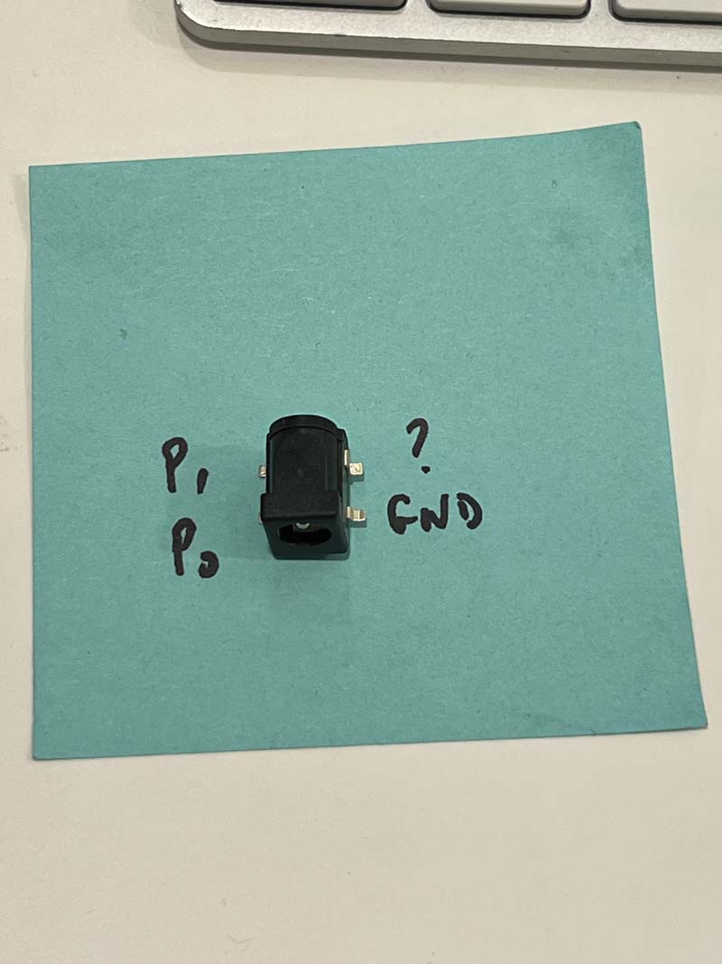
I got a bunch of 1.4mm power jacks from Quentin. I initially struggled to find their footprint but eventually realised that they were in the CBA fusion library. They have a little registration feature to make them sit well on the PCB board, which I appreciated once I found the actual footprint.
After testing the initial Anemoia PCB v0.3 and getting it to work well, I designed the next board v0.4 to accommodate all 4 pumps and relays. The board came out pretty well and initially seemed to work as intended when connected to 1 pump. So I continued to use the board during networking week assuming all was good, connecting it to rotary encoders over a wireless connection.

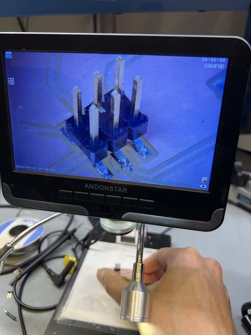
During soldering, I initially did not seat the male headers well for the relay, and actually ripped a set off while disconnecting jumper cables! It was my first time seeing that and quite surprising as I was sure my soldering was good - it looked shiny and strong. However, when I had a look under the scope, I could see that actually the amount of surface connecting the pins to the pads was minimal. Was a good learning experience. From then on, I became a strong advocate of flux and my soldering has improved by around 100% since.
I thought that would be the only issue, the next week however, I realised that in fact my wiring was wrong and I was connecting all the pumps to each other. After thinking through the issue I realised I had made a very basic mistake but I had forgotten to specify that the specific # NO terminal of the relay should correspond to a specific # positive terminal of a pump e.g. Pump 1 connects to the NO pin of Relay 1, Pump 2 <> Relay 2 etc.
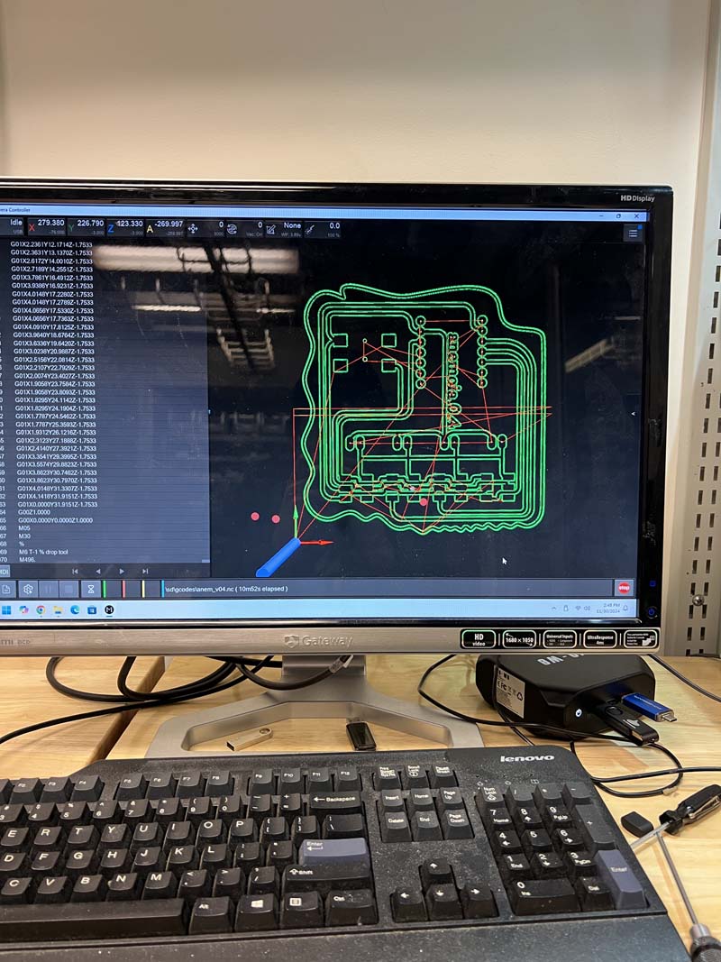
Debugging then was relatively easy, and I was able to debug, create a new schematic and make a new board within a few hours. The final board Anemoia v0.5 maintained the organic design and this time it actually worked with all 4 pumps.
I was advised against using rotary encoders by Quentin and Ling Dong. But, I didn't listen and actually in the end I was quite glad with how things worked out. I ordered some mechanical rotary encoders with a chunky feel, 18 stops, so the click for each turn feels quite satisfying and distinct, which is what I wanted.
Yes, they are super awkward to work with, they use a lot of pins especially if you're using them as buttons, and it probably took 48h longer than it would have to get potentiometers and additional buttons working with the logic I setup, but I really wanted to have a minimalist layout and the flexibility of having rotary encoders that double as push buttons was ideal.
After quite a lot of frustration, I was able to get the encoders to precisely jump from one step to another. Initially they would do all kinds of wild things like jump ahead n+2 positions. Or push buttons would double commands. All of this was quite easy to see in the Arduino IDE serial monitor though so pretty easy to debug. During networking week I was able to communicate with the rotary encoders over WiFi to control pumps. In the interface week I focused more on the actual task I wanted them to do, which was to control prompt/caption generation.
My initial plan was to create another PCB for the rotary encoders, however I simply had too many other things to do, so I decided to use an Arduino UNO and its many pins for the dials (and screen). After all, they were both going to be seated well within the eventual package/object so I felt this was also potentially unecessary. I also found that WiFi connection between XIAOs was very unreliable, so a serial connection between XIAO and UNO was a much better bet for a successful long-term demoable end product.
My code for testing the encoders is here
I assumed it would be pretty much plug-and-play, however even running the demo code initially did not seem to work even though the LED backlight turned on. After an hour or so of debugging code, I googled it and found that there was actually a potentiometer on the back of the screen that you can adjust with a screwdriver. Adjust until the screen works.
After this, while it was easy enough to send simple chunks of text to the screen, there was a challenge reading back variable, often extremely long captions generated from images. Using the Anthropic Claude API is great - Claude is an excellent writer by all accounts, but it does like to go on a bit. This led to lots of gaps and buffering issues, where Ling Dong did provide some great assistance in helping to understand why this was happening, and helping to write some code that would give the Arduino UNO the screen was connected to a bit longer to parse the data / characters.
Code for testing testing the screens is available here:
At this point everything was working well independently, and now I needed to write a program to bring everything together. Until now I had also been using an image stored on my computer to test, so I started by getting together a program to read an image via webcam, taking an image repeatedly, then storing (and overwriting) so that there would always be an image for the system to process
Image capture code available here
For the main program I needed to do the following:
Taking a photo of an image is explained above. Captioning an image via Claude API is achieved as follows. It is limited to 145 characters to ensure that the screen output is reliable and fast. It also offers a better user experience.
PSEUDOCODE:
// Define API request message format
MESSAGE = {
    type: "text",
    content: "Provide a detailed, comprehensive caption for this image
              in a few precise sentences, prioritizing the subjects.
              Limit the output to 145 characters."
}
To generate the caption:
PSEUDOCODE:
// Generate caption using AI API
TRY:
    response = CALL API client.messages.create WITH:
        - model: "claude-3-5-sonnet-20241022"
        - max_tokens: 300
        - messages: [message]
    RETURN response.content[0].text
It’s simply a matter of knowing what ports are connected, and if using the same setup this should be the same each time, e.g.:
PSEUDOCODE:
// Serial configuration for Arduino Uno and Xiao ESP32S3
SET ARDUINO_SERIAL_PORT = "/dev/tty.*****"
SET XIAO_SERIAL_PORT = "/dev/tty.******"
SET BAUD_RATE = 115200
For the encoders, as they will likely always be in different positions, it is important that they start at 0 and that the button state is defined as false, which is done as follows:
PSEUDOCODE:
// Initialize encoder states
encoder_positions = [0, 0, 0]
last_encoder_positions = [-1, -1, -1]
button_states = [False, False, False]
PSEUDOCODE:
// Function to extract subjects from caption
FUNCTION extract_subjects(caption):
    // Create prompt for AI to identify subjects
    prompt = "Extract the main subjects from this caption: " + caption
    prompt += "Provide them as a numbered list in format:"
    prompt += "1. [Subject 1] (living or non-living)"
    prompt += "2. [Subject 2] (living or non-living)"

    // Query AI API
    response_text = CALL query_gpt(prompt)

    // Parse response
    subjects = EMPTY LIST
    FOR EACH line IN response_text.split_by_newline():
        IF line contains ".":
            parts = line.split_by(".", limit=1)
            IF parts has more than 1 element:
                ADD parts[1].strip() TO subjects

    // Set default if no subjects found
    IF subjects is empty:
        subjects = ["Default Subject 1", "Default Subject 2"]

    RETURN subjects
This then gives us specific options on the screen for the user to select in relation to the time-period of interest of the living or non-living thing that is selected as a main subject
PSEUDOCODE:
// Determine time options based on the first subject
first_subject = subject_options[0]

IF "non-living" IN first_subject.to_lowercase():
    time_options = [Life-Cycle A]
ELSE:
    time_options = [Life-Cycle B]

mood_options = ["option A", "option B", "option C", "option D"]
For the scent generation, I worked with AI to help convert the memory sentence into a specific scent formula. The AI selects from predefined smells (e.g., Campfire, Night Air, Rain) and assigns proportions to create a unique combination that best reflects the generated memory. The output is a formatted list of four scents with their proportions, such as:
There is also a function, generate_pump_times that assigns each scent to one of four pumps, translating the proportions into specific durations (in seconds) for which each pump should run. For instance:
Finally, we have the logic for the encoders, and buttons. The program continuously runs in a loop, checking for changes in the encoder positions and button presses. Users interact with the system by turning the encoders to select values for Subject, Time, and Mood and confirming these selections using buttons. Once all inputs are confirmed, the program generates a “final prompt” and the scent formula.
PSEUDOCODE:
// Main program loop
WHILE True:

    // ENCODER 1: Subject selection
    IF encoder_positions[0] changed:
        index = encoder_positions[0] modulo length(subject_options)
        selected_subject = subject_options[index]
        DISPLAY "Current Subject: " + selected_subject
        UPDATE last_encoder_positions[0]

    // ENCODER 2: Time selection
    IF encoder_positions[1] changed:
        index = encoder_positions[1] modulo length(time_options)
        selected_time = time_options[index]
        DISPLAY "Current Time: " + selected_time
        UPDATE last_encoder_positions[1]

    // ENCODER 3: Mood selection
    IF encoder_positions[2] changed:
        index = encoder_positions[2] modulo length(mood_options)
        selected_mood = mood_options[index]
        DISPLAY "Current Mood: " + selected_mood
        UPDATE last_encoder_positions[2]

    // Handle button presses for confirmation
    IF button_states[0] pressed AND selected_subject exists:
        DISPLAY "Subject Confirmed: " + selected_subject
        SET button_states[0] = False

        // Recalculate time options based on confirmed subject
        IF "non-living" IN selected_subject.to_lowercase():
            time_options = ["raw-materials", "manufacture", "in-usage", "decay"]
        ELSE:
            time_options = ["childhood", "youth", "adulthood", "elderly"]

    IF button_states[1] pressed AND selected_time exists:
        DISPLAY "Time Confirmed: " + selected_time
        SET button_states[1] = False

    IF button_states[2] pressed AND selected_mood exists:
        DISPLAY "Mood Confirmed: " + selected_mood
        DISPLAY "Generating Final Prompt..."

        // Generate final memory sentence
        final_sentence = CALL generate_sentence_with_mood(selected_subject, caption, selected_mood)
        final_sentence = REMOVE newlines FROM final_sentence
        final_sentence = NORMALIZE spaces IN final_sentence
        DISPLAY "Final Prompt: " + final_sentence
        SET button_states[2] = False

        WAIT 8 seconds
        DISPLAY "Generating Anemoia..."

        // Generate scent formula and control pumps
        scent_formula = CALL generate_scent_formula(final_sentence)
        PRINT "Scent Formula: " + scent_formula

Creating the Anemoia Device involved 3D printing, laser cutting, and quite a lot of trial and error. The goal was a very clean design, based on the metaphor of distillation that could support the electronics but retain an aesthetic and mysterious form. It should of course be capable of holding liquids and tubes and allow fragrance oils to flow through the system without interference with electronics.
It was quite challenging to figure out how to cleanly and aesthetically attach everything together. In the end this was achieved with a series of brackets that held acrylic sheets in place. This was 3D modelled in CAD and then through a lot of test 3D printing on the Prusa MK4 and MK4s, eventually the right fit was found. Final prints were mostly done with a Bambu Carbon X1.
To package things, I procured a nice set of 8x10 inch frosted acrylic sheets. The acrylic sheets themselves were laser cut. 4 panels are used to form a box that holds the electronics in place. This separates out the pumps (on a lower level) from the other electronics (on an upper level). The front panel has slots for the dials and the screen. The side panels slot together to hold things in place. The top and bottom panels are attached via the bracket system.
Below this, there is a further panel that houses the fragrance oils in tube holders. Right at the top is a shield for the webcam, which allows the webcam to sit flush and face down. All electronics are mounted carefully and secured in place to ensure strain relief as far as possible. The PCB is seated within a 3D printed cartridge slot.
The Anemoia device was successfully demonstrated at the How To Make (Almost) Anything demo day, with a memory generated about the Great Wall of China. Neil reminisced (jokingly) that it did make him feel nostalgic for the Great Wall. The project is now being developed further to explore the connection between AI, memory and scent, through research papers, user studies and product development.

