Week 2:
Computer Controlled Cutting
- Project Management: Build a personal site in the class archive describing you and your final project.
- Computer Controlled Cutting:
- Group assignment:
- Do your lab's safety training.
- Characterize your laser cutter's focus, power, speed, rate, kerf, joint clearance, and type.
- Individual assignment:
- Cut something on the vinyl cutter.
- Design, laser cut, and document a parametric construction kit, accounting for the laser cutter kerf, which can be assembled in multiple ways. (For extra credit, include elements that aren't flat.)
- Group assignment:
Website
I initially wanted to build a site using a static site builder with the expectation that it would make the process of documenting my work easier. However, with the way the repo has been set up, using something like Hugo would entail either making edits to the .yml file (which I tried and broke my repo) or maintaining a local version and pushing that to the repo.
So in the end, I decided to just go with pure HTML/CSS/JS as I’m already familiar with this and it also gives me more flexibility on the design of the website, especially adding weird interactive things like
I kept the design clean and simple so that it can work across devices.
Had to briefly refresh some git basics, but the overall setup was quite simple: establish ssh connection, clone the repo to local machine, setup basic website structure (index.html, whatever.css, etc), check git connection/status, add files, commit and push.Computer Controlled Cutting
For the group assignment, a few of the CBA group met up on a Saturday to cut some cardboard on the laser cutter.
I am new to CAD and Fusion, so I spent quite a bit of time during the week trying to get familiar with the software and doing some basic exercises like modeling.
Group Assignment
We worked with stock cardboard, which had a variable thickness of between 3.5mm - 4.0mm.
Summary:
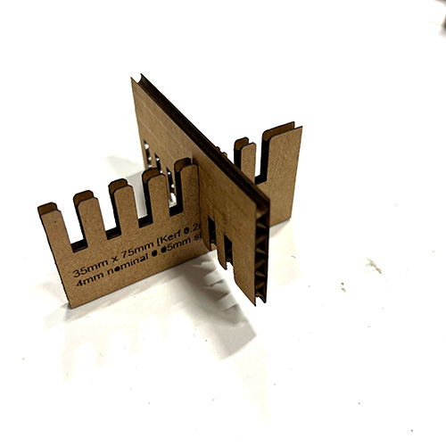
- Determined the kerf to be 0.2mm.
- Made combs with and without chamfers to test different interferences and lead-ins.
- Tested some press-fit, chamfer options, and snap-fit joints.
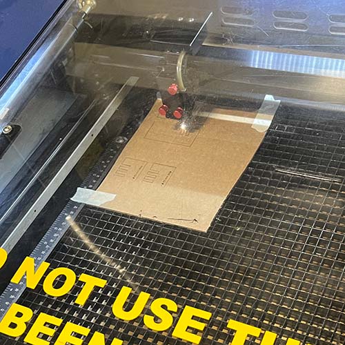
Results:
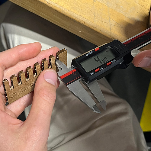
After cutting, we estimated the beam size to be around 50.00mm to 49.90mm, with a kerf of 0.1mm to 0.2mm. Half of the kerf is approximately 0.05mm.
We found the kerf to be 0.2mm after a lot of testing.
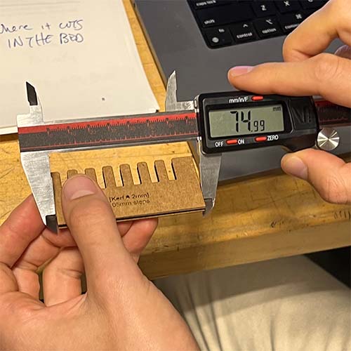
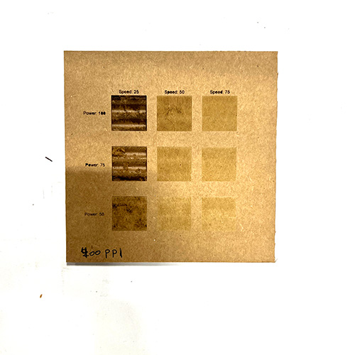
Cut Settings:
| Type | Speed | Power | PPI | Outcome |
|---|---|---|---|---|
| Cut | 2.8 | 100 | 200 | Needed multiple passes |
| Cut | 2.1 | 100 | 200 | Cuts well but some small flames |
| Raster | 50 | 100 | 200 | Best result on cardboard |
With the kerf established (0.2mm), we offset the cutting profile by 0.1mm larger. We found the best press-fit was 3.90mm nominal, giving us an interference of 0.1mm.
For an example joint: following kerf/2 + interference = toolpath will give you your desired outcome.
Parametric Construction Kit
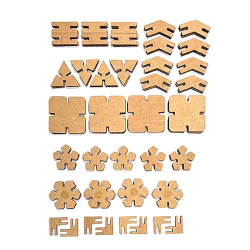
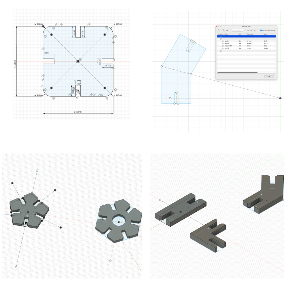
For this task, I wanted to try building a simple puzzle piece that was capable of constructing various forms and even curved structures. Given the time constraints, as I’m new to CAD, I decided to focus on learning the tools well rather than constructing a specific object for now, although I have a clear project direction in mind.
- I sketched out a basic kit comprised of 4 polygons: triangle, square, pentagon, and hexagon.
- From previous experience, I knew about slots to allow pieces to fit together, so I sketched some basic ideas for this, including chamfer/lead-in.
- I then thought about the types of connectors that could help realize this: straight, angled, and right-angles.
- Next, in CAD, I started drawing the shapes. Through this process, I learned a lot about Fusion, particularly about constraints, how to properly set parameters, and general workflow.
I worked parametrically. For the shapes, I set the following parameters:
- Shape width/length (depending on the shape)
- Slot thickness
- Slot length
- Chamfer
- Kerf
Slot thickness was given by the thickness of the cardboard +/- kerf. For internal measurements, I adjusted by removing kerf (e.g. slot_thickness - kerf), and for external measurements, I added kerf (e.g. width + kerf).
For the shapes:
- I drew polygons and set the number of sides (e.g., 5).
- The optimized process for drawing slots is as follows:
- Fully constrain the initial shape and set parameters.
- Draw a perpendicular construction line at the center point of a flat side (e.g. the base of a triangle).
- Set offset (e.g., -1 * (slot_thickness / 2) and slot_thickness / 2). This creates two lines on either side of the initial construction line. Then simply connect those two lines to create the slot, ensuring it is always centered.
- Use the circular pattern tool to apply the slot at precise geometries around the shape (it just works).

For the connectors:
- I used a slightly different process. I started by sketching my ideas, then in Fusion, drew half of the shape, constrained it, and drew a slot as described above.
- For the straight connector, I used the mirror tool to complete it.
- To make a connector that can be produced with an arbitrary angle:
- Set a parameter: "angle".
- Draw a horizontal line about the origin.
- Draw another line from a point on the horizontal line at an angle (close to your intended angle) and set that value to the "angle" parameter.
Laser Cutting
Based on the group exercise, my initial design featured slots that were around 4mm and I assumed a kerf of 0.1mm from the group exercise. This meant the slots should be around 3.9mm when cut.
In reality, the cardboard I used was pretty uneven, measuring between 3.5mm and 4mm. I ran a test cut, adjusting the speed slightly to 2.3, and using my existing measurements to see what would happen. It cut perfectly, however the pieces came back far too loose. I adjusted my drawings to slot_width = 3.7mm (which was pretty fast with parametric design) and the result was pretty good, with all pieces fitting very snugly.
I lost a bit of time by stopping to cut and going to office hours (although certainly worth it long-term), but it meant I had to setup everything again when I returned, and also something weird happened with my files where perhaps me working across multiple files caused some changes (to investigate). I also tried to optimize the use of the material with my design and layout on the laser cutter, which consumed a bit of time. Fortunately, I did my cutting on Monday because on Tuesday there was a fire from someone else laser cutting, but I was also keen to avoid the last-minute rush by working early, and this turned out to be a wise idea.
Results
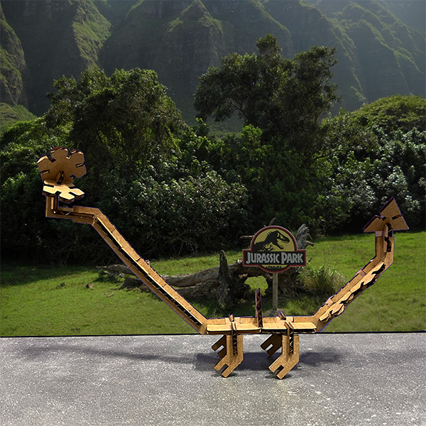
The final cuts came out well, with the 4 polygons plus 3 types of connectors. My main goal was to get better using Fusion, test out the laser cutter, build something with curved features, and have a kit that could pretty much build anything.
I wanted to use this week as a way to build some mastery with the tools, rather than simply building the idea I have, as I typically skip this step and then run into problems down the line. I think my kit accomplishes my goals; I've figured out the core aspects of Fusion, was able to translate that into meeting all the weekly goals and was even able to figure out a way to develop a parametric angle for the curved connector which means this could be customized to work for any given shapes.
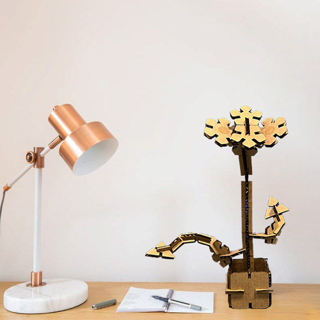
To demonstrate that, I built a rudimentary cardboard potted plant with curved branches with some of the pieces, and then a sauropod trying to eat the plant with some of the others (because why not).

Bonus: Vinyl Cutter:
With the vinyl cutter, I printed out a sticker of the Dymaxion projection popularised by Buckminster Fuller. The Dymaxion projection, is a kind of polyhedral map projection of the Earth's surface onto the unfolded net of an icosahedron. The resulting map is heavily interrupted in order to reduce shape and size distortion compared to other world maps. Printing went pretty smoothly and I was able to pull-off the sticker quite cleanly. Only the black sea did not remove during the initial peel off but I was able to life it off with a pair of tweasers.
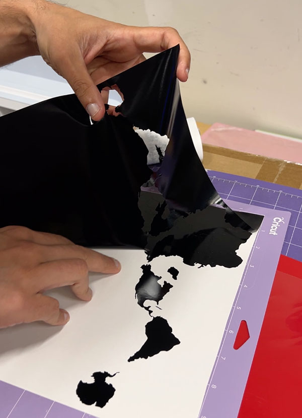
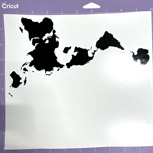
My Mistakes:
- I initially did not understand constraints very well. I thought basic things like right angles would be constrained logically, or that a slot would probably be constrained at the center point if drawn a certain way. In the end, properly constraining is a very cumbersome process and requires a forward-thinking, systematic workflow.
- Similarly, with parameters, I made the mistake of adding parameters after drawing things, instead of parameterizing ahead of time based on a simple sketch and giving it two minutes of thought before diving in.
- I spent way too long troubleshooting, for example, trying to constrain a slot to remain centrally positioned along a vertex. It took over an hour, as it was hard to find relevant tutorials that explained the concept.
However, by spending this time, I became far more comfortable and confident with the software, learned a lot about how constraints actually function, and can now probably model much faster in the future.
My Learnings:
- I also learned about the power of construction lines, which are very helpful.
- I figured out how to use circular patterns and mirror tools to replicate slots.
- I attended an office hours session, and because I had spent this time, I was able to ask very well-constructed questions. I worked with the instructor to go through how they would have done what I had done. They showed me how to use offsets to create slots that automatically stay centered versus my more haphazard approach.
- Draw construction lines! They can help with all kinds of geometric operations and constraints later.
- You don’t have to draw cutouts in sketch mode. Just draw a shape you might want to cut out, finish the sketch, and then extrude. For example, with slots, you can just draw rectangles where a slot might be, then extrude, which automatically creates the slots and preserves the constraints.
- Apply chamfer in 3D mode rather than in sketch mode to preserve your constraints.
Useful Resources:
- Good tutorial on constraints and setting things to the center
- Parametric House - Triangle Pavilion
- Press Fit Kit Tutorial
- Creating Joints (Video Tutorial)
- More Joint Tutorials (Video)
- Arranging (from 3D to 2D Layout)
