Week 5: Electronics Design
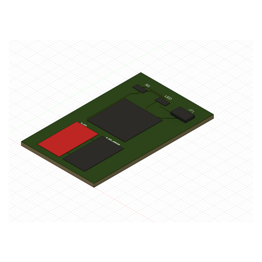
This week the assignment was:
- Use an EDA tool to design a development board to interact and communicate with an embedded microcontroller
- Extra credit: try another design workflow
- Extra credit: design a case for it
I have some basic familiarity with designing circuits from my time on the IDP at CIID; however, I have never designed or worked with a PCB. In fact, I probably thought I never would have to do that.
We were presented with a few options on how to design the PCB:
- KiCad, which looks very powerful
- Eagle, which is now built into Fusion
- SVGPCB, which has a different spin on PCB design allowing for pure code or pure drawing
- JSONPCB leomcelroy.com/json-psb
- Flux, which is an AI tool for PCB design
I decided to use Fusion as I’m generally keen to improve my skills with that software and thought it’d be good to build holistic skills with both 3D modeling and electronics design within Fusion.
Thinking about what I might need in a final project, I looked for components in the Fusion library that might work.
Requirements:
- Microcontroller with wireless capabilities
- Camera for visual inputs
- Microphone for sound inputs
- GPS
- A nice chunky button, something like this
- Storage
I had a look at simple sources like Sparkfun as references for parts as I built. I had a look at a few microcontrollers and decided to work with the Xiao ESP32 as it seemed powerful and has great connectivity, which could be useful to stream data or even provide location information indoors via Wi-Fi.
Next, I followed a few tutorials to get started on designing electronics with Fusion. This one was quite helpful: YouTube Tutorial.
I was able to draw out my circuit; initially though, it was a mess of lines everywhere and very hard to understand. It was also pretty difficult to understand how to map pins between the ESP32 and the XIAO ESP32 board. I went to office hours and spoke to Quentin, and we went through a couple of pretty important things.
Firstly, using labels and names instead of having wires everywhere. This would mean the wires still route to the same thing, e.g., ground or SCL (Serial Clock Line), but without messy wires in the schematic.
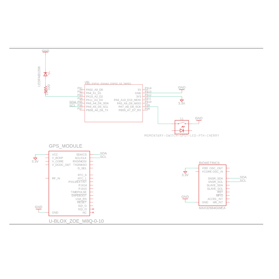
Secondly, with a bit of deep searching, we found this schematic reference for the XIAO_ESP32 which helped a lot in terms of understanding which GPIO of the ESP32 map to the pins of the XIAO.
Finally, we also dug a bit into some other topics, like the fact that the version of the ESP32 that we have at the Fablab already has a camera and mic onboard, so there was no need to use additional components, and I could redraw based on this.
I went away and redrew the circuit based on this and was able to get to the actual PCB design step. In Fusion, there are a lot of convenient tools like auto-routing which give a great first attempt at routing which can be tweaked later.
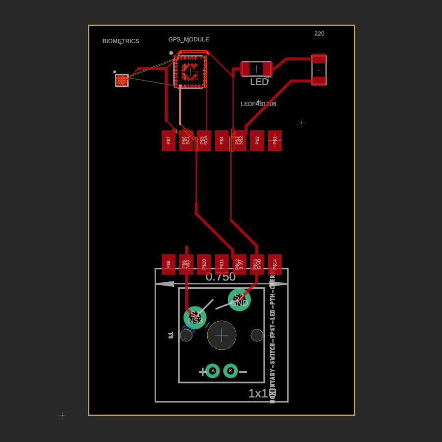
I then went to office hours with Anthony to see how my PCB design looked. The schematic was okay, but Anthony had a lot of concerns about my PCB design.
Firstly, I had drawn everything on my PCB with the default 6mm width. This was far too thin to do as a novice, and he guided me on how to set the thickness of traces to something more realistic, like 16mm. This is done by using the DRC command that brings up the Design Rule Check. We set these items to 16mm and then tried to redraw routes. Of course, because the board was already laid out for 6mm connections, some of the spacing that previously had worked for routing no longer worked.
Secondly, Anthony taught me about the difficulty in working with some of the parts natively. For example, with the switch button I had selected or the biometric sensor, it would be very challenging. A better option would be to design a layout with intended functionality using something like a 4-pin header as a placeholder for the actual part later. While Fusion has a lot of real parts in the library, a lot of the settings are designed for professionals who can work to a more precise level than we will likely be able to do without specialized tools.
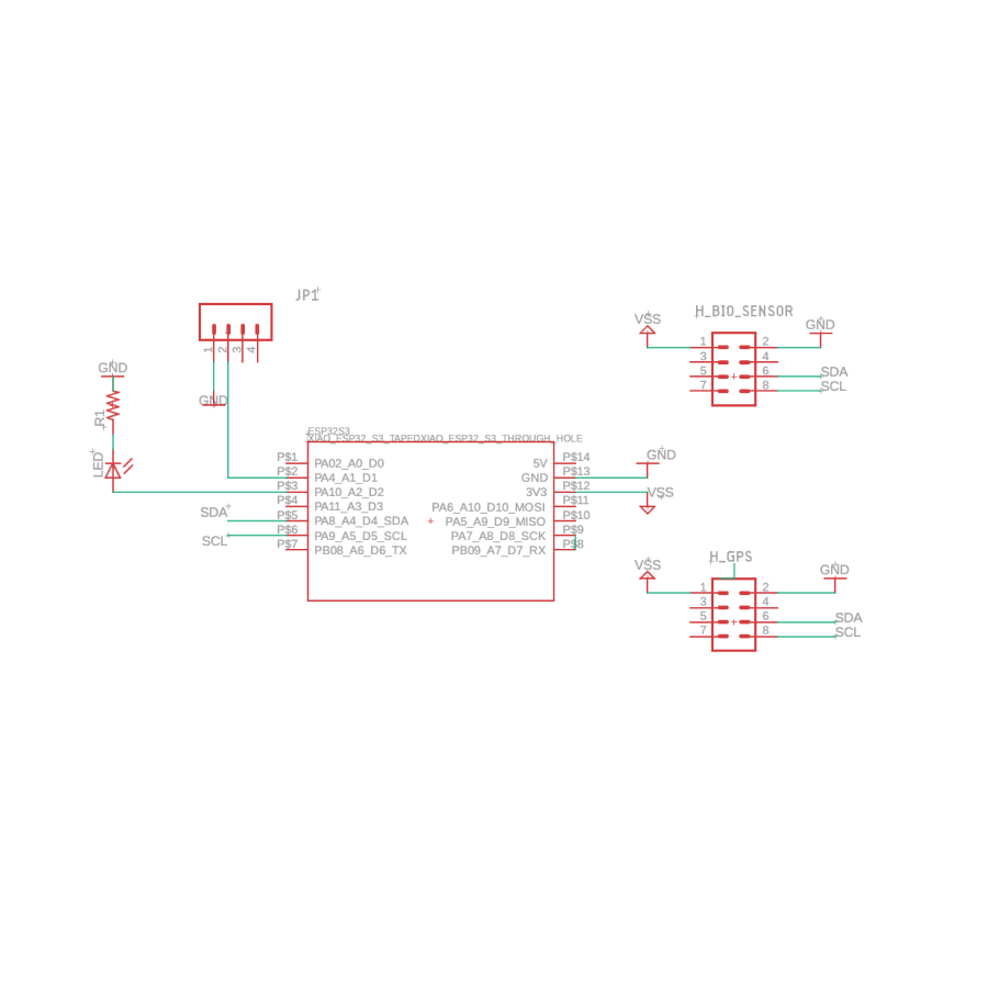
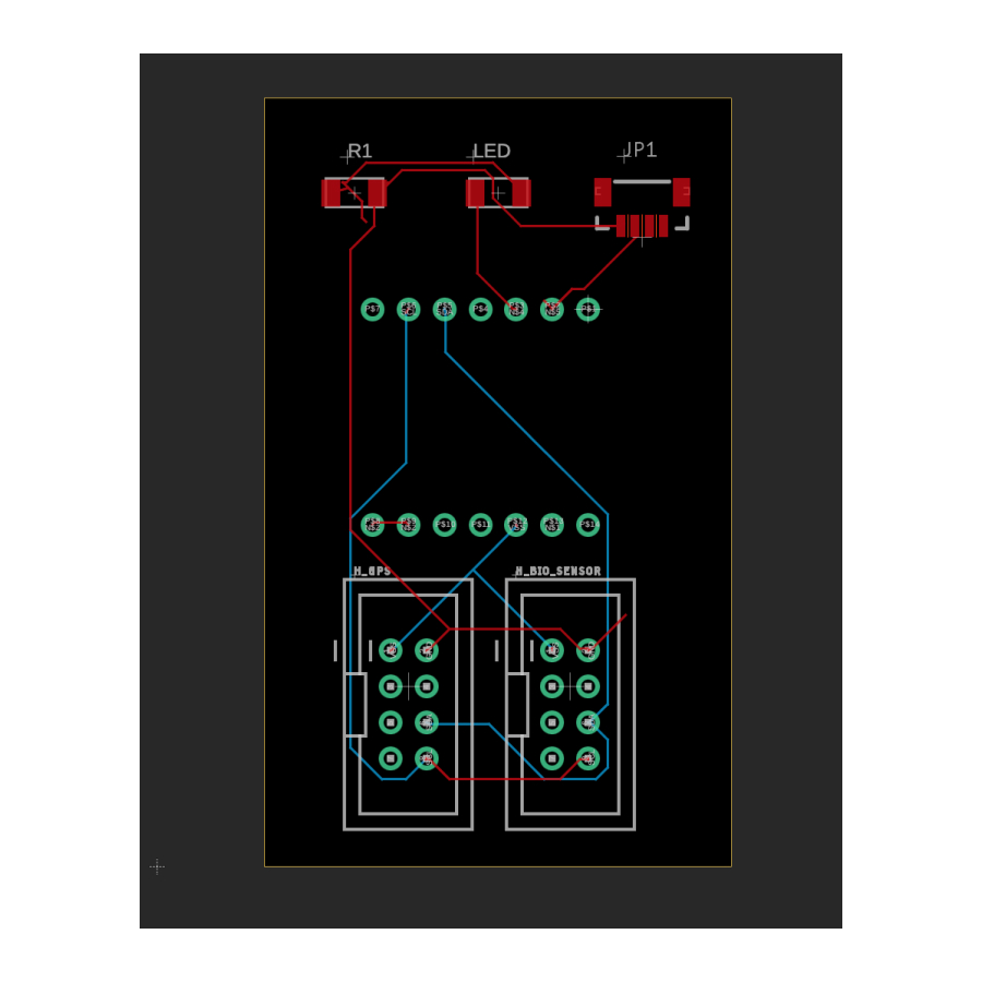
So with this in mind, I redesigned my board, using headers in place of the biometric sensor, GPS, and button. This simplified things greatly in my schematic and in the eventual PCB design. The design that was generated within Fusion for the PCB uses 2 layers.
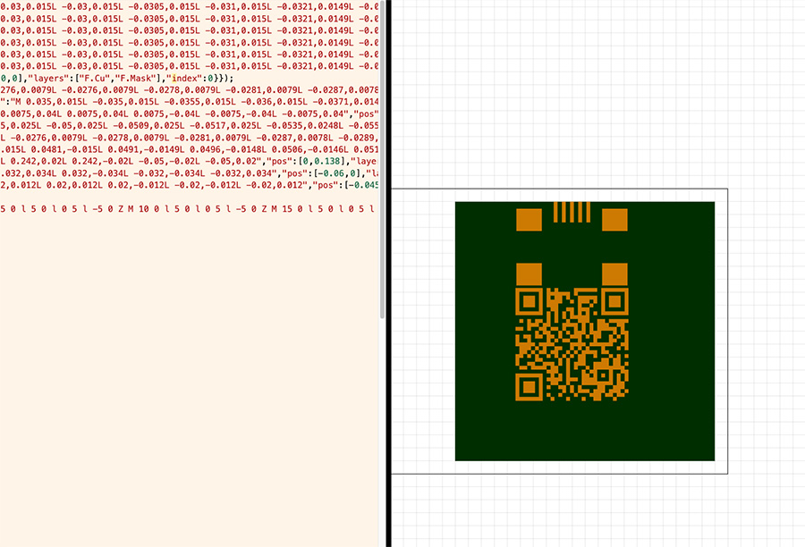
Beyond this, I wanted to try out some of the other tools. I tried SVGPCB as I had an idea to try to make a PCB layout that is in itself a QR code (rather than just featuring a QR code). I initially tried to see if there was a way to convert a QR code image into a vector drawing in the canvas, but didn't find a good way to do that. I also tried generating an SVG via python, import that into SVGPCB which displayed, but seemed to create automatic connections between points that were far too challenging to edit. I then saw there was an example where the QR code was drawn on the canvas in javascript so started looking into that but didn't manage to get anything ready for Wednesday's show and tell. This could be a fun little experiment over the weekend.
During the group session with Quentin, we looked at the use of multimeters, oscilloscopes, and even a new shiny USB-based oscilloscope.
