Week 7: Moulding and Casting
Assignment
This was a really interesting week for me, as of course it is something I have never done before. In class we learned about different types of moulding, here’s a quick recap of some cool things we learned during the lecture:
- Flexwax is ideal for moulding to copy an object.
- There are Algae derived gels in which you ‘can put anything in there’ e.g. for life casting it’s great.
- PDMS nanostructures
- We also covered a library called Materiom for biomaterials
- We were told that this week we’d be using ‘smooth on’ https://www.smooth-on.com/
Neil gave us some high level instructions on casting preparation:
- Mix the two parts 1:1
- Pour into a cup and ONLY horizontal stirring to avoid bubbles. This might take a while. The idea is to stir until the colour is uniform.
- To avoid bubbles something you can do is apply a pre-coat especially to corners and fine details
For this week we were told we could print or machine moulds. Printing with FDM is too low resolution so we would be using SLA printers. However, the main goal was to learn how to use a mill to create a mould and then cast it.
During the Recitation we covered Fusion CAM = manufacturing part of fusion that will create a path plan. It is a relatively complicated operation with lots of steps and lots of ways to get things wrong.
Training and getting started
I had scheduling conflicts and we also had 99Fridays and a hackathon this week so I missed all the trainings and was only able to get trained on Sunday. I learned how to operate the Gemitsu CNC machine which is a lot more complicated than the Carvera in terms of operating. Safety is very important with this machine and a lot of things can go wrong.
In order to create our moulds, we would be using the CNC to cut into wax. Wax mills well and is pretty forgiving. This week, to start out we’ll be using various types of milling ends (not drills) that remove material.
After creating a mould, in Fusion we would be using the CAM section of Fusion to setup path planning. To make the mould, I started with an STL file. After importing as a mesh, I then scaled it down a bit and reduced it (reduced number of faces) to make the geometry more simple for my laptop. Next I converted the mesh to a solid to work with it to make the mould.
Modelling in Fusion
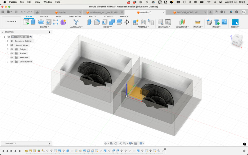
I modelled the wax block - 7 x 3 x 1.5 inches, shelled it out leaving a 8mm thick wall around it, and placed the two parts of my mould on either side of the shell. The initial STL I worked with was an organic mushroom shape that had a flat side which I thought might work as a two part mould.
I also later modelled another mould which was a single shape. To split it, I constructed a midplane (construct —> midplane) at a centre point and split solid into two parts before following the above.
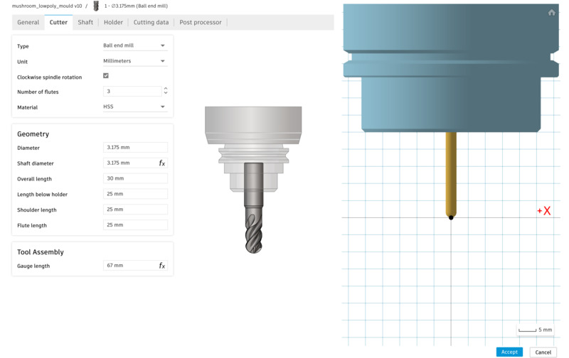
Once the modelling was done I was ready to start getting my file ready for milling. Heading into the manufacturing section of Fusion, I created a new setup. Next I selected the correct tools for the machine. This week we worked with 2 milling ends; a 6.35mm flat end mill for an initial pass and a 3.175mm ball end mill for finer details. They were provided as a library by the CBA team.
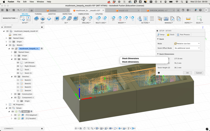
For the larger flat end mill, the idea is to remove as much material as possible with a ‘rough’ pass, not optimising for detail, but for speed. In setup, we select our model (by selecting bodies), we orient the axis to make sure x, y and z are pointing the right way as shown below.

In the stock tab, we select the stock, but in reality we can simply select the option ‘no additional stock’ which will orient the axis to the origin point of the stock if correctly selected in the prior step.
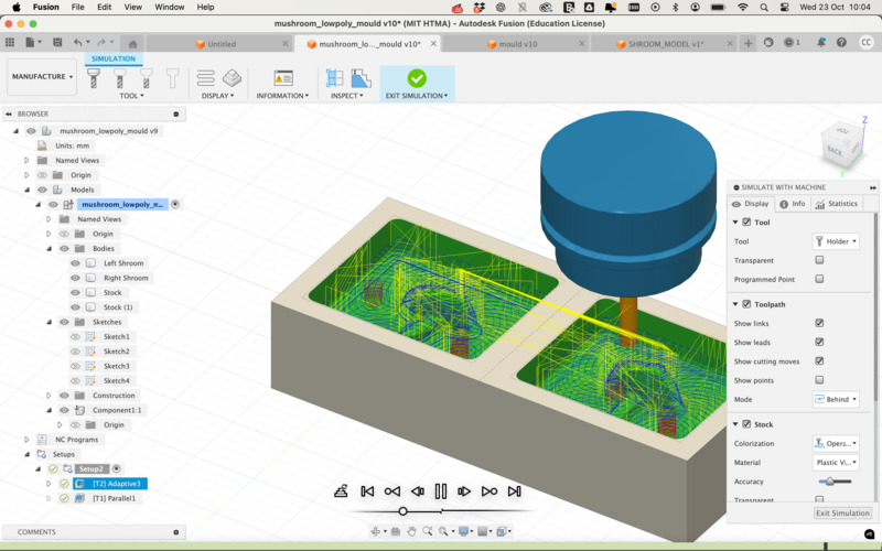
Next, I selected Adaptive Clearing from the 3D menu. Within the menu, in the first tab, I simply chose the correct tool (6.35mm). In the geometry tab, I set Machining Boundary to ‘none’. In the Heights tab, I set the offset to 0. In the Passes tab, I set Maximum Roughing Stepdown to 6mm, which is roughly the same size as the tool. I added fillets for the sharp corners. With that done, I hit OK and within Fusion we can then simulate the Tool Path to see how it is moving around the model and should mill in real life.
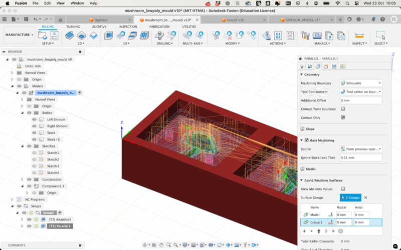
For the finer details, we were advised to use a Parallel finishing strategy. The setup for this is quite different. Firstly, the tool is the 3.175mm tool.

Before going on to the next steps, I will discuss a few issues I ran into.
- With my first model, I initially saw a huge amount of errors (> 399 errors) after simulating. This was very tricky to troubleshoot as I did not really understand what was going on at all. Another student told me it was due to collisions, and how the milling tool might actually interact with the physical stock. The collisions seemed to be occurring due to the depth of my model which was pretty tall but thin.
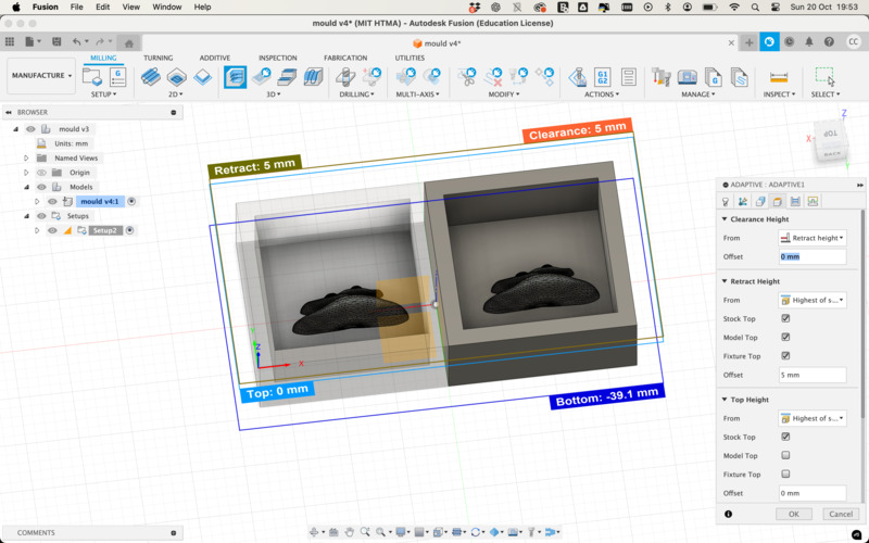
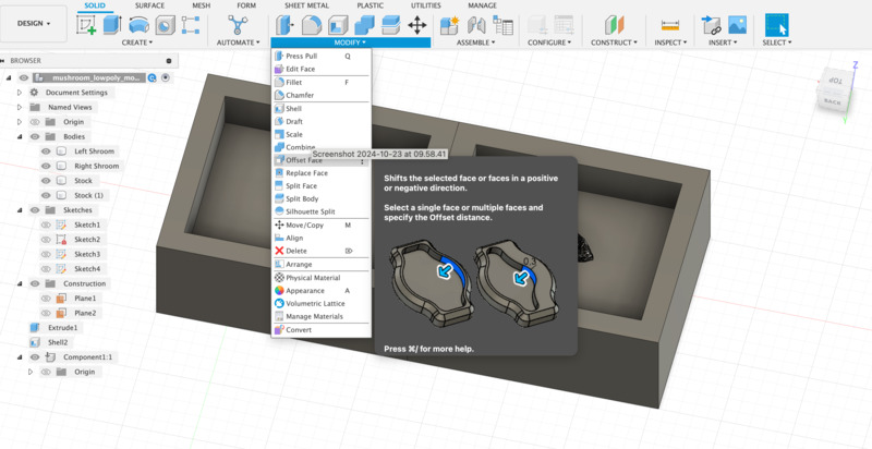
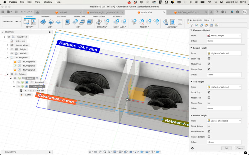
I scaled the model down a bit and also used “Offset Face” back in design mode to raise the supporting face of the stock up a bit, and also then moved the model up to meet it. This also did not work so it seemed to be more about the height differential between the model and the supporting base compared with the height of the tool. One way to kind of fix this was to set an offset height in Fusion. The screenshot below shows the setup that eventually worked for me, but 15mm is a very large offset and realistically it is better to remodel as the finish was not ideal.
- With my first model I did not optimise my model correctly; it had far too many faces and details, which meant everything was incredibly slow. It also perhaps caused the simulator to crash frequently which made doing anything extremely challenging. In hindsight it may have been faster to just start again as my second model was a lot faster for me to work with and less taxing on my machine which led to less errors and frustration.
Milling
The next step was to export the gcode. This is done per operation e.g. one for the Adaptive pass and another for the Parallel pass via Actions > Post Process. Simply select GRBL file format, and give your operation a name e.g. Cyrus_adaptive. This will then export a file to the selected directory in the file format .nc
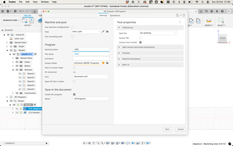
From here I saved the file to a micro SD card and inserted it into the controller for the Genmitsu CNC machine. To operate this machine here is what I did:

- Put on my safety gear (eye protection), cleaned up with the vacuum cleaner and cleaned the suction.
- Glued my block of wax onto a copper plate and clamped it down on the CNC.
- Inserted the first tool (6.35mm roughing tool) and used the wrenches to tighten.
- Used the controller to set X0 and Y0 at the bottom left corner (and origin) of my wax block and operation.
- After setting this, I placed a piece of paper on the block and set the Z0 carefully by moving the head to a more central area of the block, and gradually moving it down on the Z-axis while gently shifting the paper, until the paper would no longer move. After setting the Z0, I carefully moved the head up on the Z-axis.
- I then double-checked that X0 and Y0 were set correctly by using the move to XOYO button, turned on the suction and the mill, and started the operation.
With my initial model, the mill took quite a while on my first job ~48 minutes and around 12 minutes for details. It wasn’t really worth it and was due to me not having done a good job of modelling and thinking through the steps rather than warranting the length of this job.
Second time round I thought things through much better and got the job down to 25 minutes and 6 minutes respectively. Milling time displayed in Fusion is slightly optimistic.
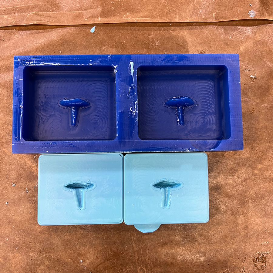
Here is the result:Casting
With the hard mould ready, we were then shown by Marcello how to cast into it. It should be said to always wear gloves and workwear when doing this part of the process as it gets EXTREMELY messy.
The first step was to create a flexible mould - for this we used OOMOO which was pretty fun to work with. The variant we worked with comes in a box with 2 parts, Part A and B, which are mixed in equal measures 1:1. The pot life is around 15 minutes and it cures in 60 minutes.
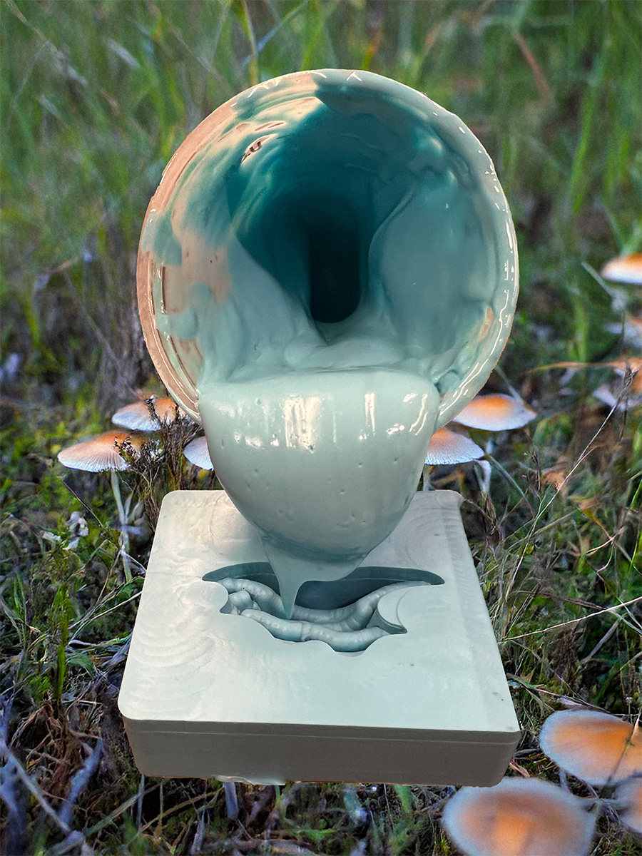
I mixed it into a cup following the instructions, being sure to only stir horizontally, it does take a very long time to actually mix though. First time around, I then carefully poured it onto my mould. The goal was to try and avoid air bubbles and they are very hard to avoid. As a group we then began slamming our moulds (to get air bubbles out) onto the table which created a lot of noise!
We then let the OOMOO cure, and I played around a bit to make a pot sculpture
While the OOMOO cured, we were then onto casting. For this we used a type of clear plastic from smooth-on.com. Again mixed 1 to 1, and a lot of stirring and bubble avoiding. However, this is much more hazardous and it was important not to inhale any of the fumes coming from the mixed materials.
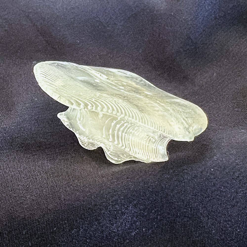
With the clear plastic, in theory we should also use a vacuum to remove air bubbles but it seems like the vacuum we were using didn’t work very well. The pot life of the clear plastic is a lot shorter than the OOMOO, so I poured it into my new silicon mould pretty quickly. It cures very fast which means you can also have fun trying to make more cup sculptures!
After pouring I realised pretty quickly that I’d made quite a large error with my first model and that the two parts would not line up symmetrically, which is why I began working on a second model on Tuesday.
Here's how the pieces came together
I did find a good video here which goes into great details about moulds and registration: YouTube Video, which could be a good reference to come back to.
SLA Printing
Another way to make the mould would be to use an SLA printer which prints at high resolution. I wanted to try out the Formlabs printer, so while waiting for my silicon mould to cure, another student and I sent some files to print.
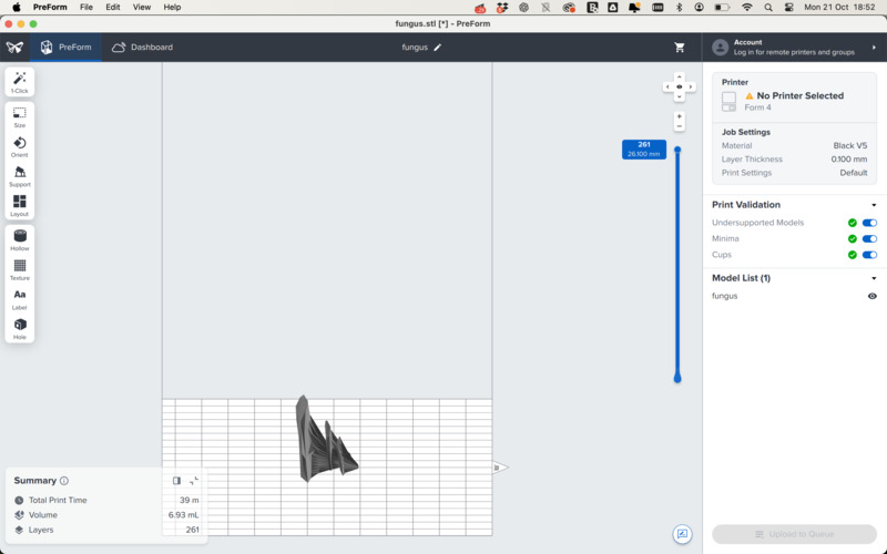
The Formlabs software is pretty amazing and creates the relevant supports for you. The print time was quite long - nearly 4 hours for the two models we sent on the same job. We didn’t actually print the models as moulds to save time but in the end it would probably have made more sense to do so.
After the print is complete, you remove the print from the build platform, rinse the print in Isopropyl Alcohol in the Form Wash, and cure it. I didn’t get a chance to work on the finishing steps so will have to do this soon to integrate the knowledge.
The actual print came out really beautifully and captured a lot of the fine details, so I look forward to experimenting more with this machine.

Modelling Mushrooms and Food Safe
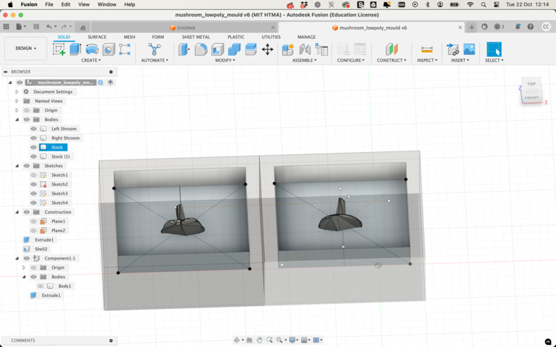
Late Tuesday night, I started to model a second mould and found some time to mill a second wax mould.
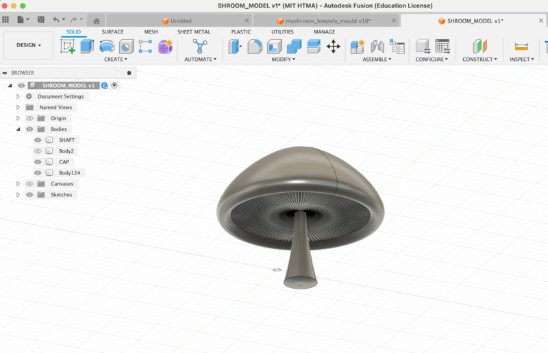
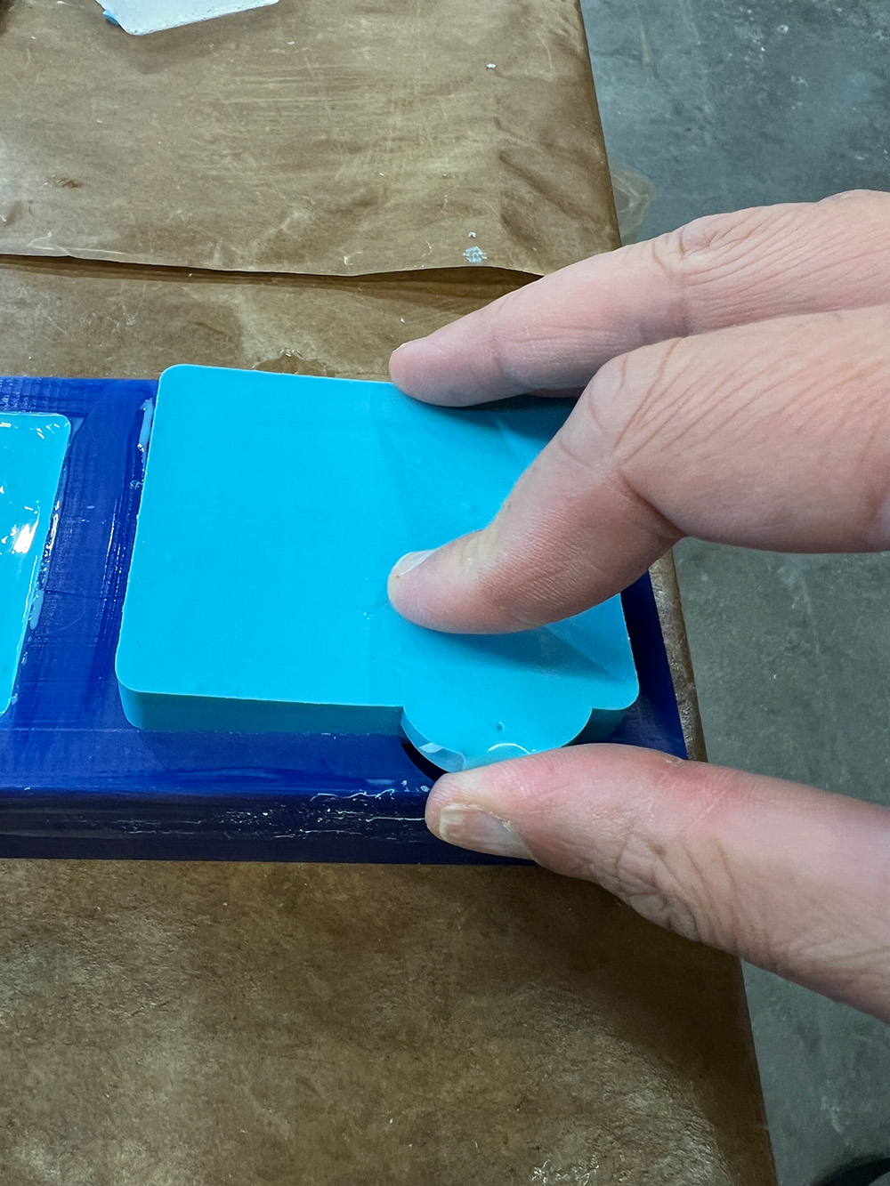
I also tried out some of the Food-safe casting materials. They were really tricky to work with and created an enormous amount of bubbles. On Wednesday morning I checked on last night's moulds which came out pretty well, I also realised that a tab design into the initial wax would be very convenient as a way to extract the silicon easily!
