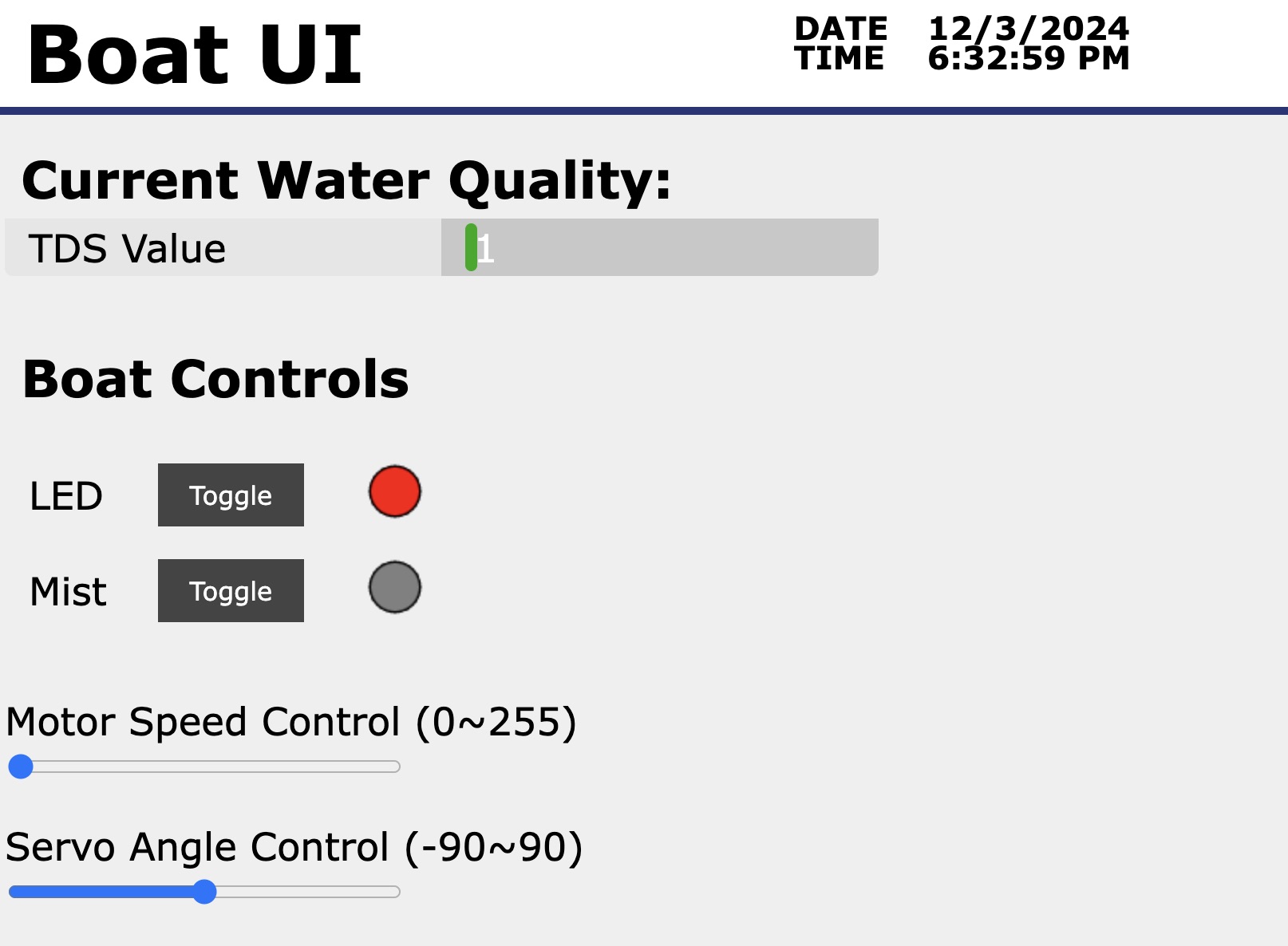
This week, I built a webpage UI with HTML and JavaScript and created communications to control the electronics for the board I made last week. Different from last week, I configured the XIAO ESP32C3 as an access point (AP), so that clients could interact with the ESP32C3 directly. This method had an advantage that no external WiFi connection was needed. The delayed response issue from last week did not show up again. I also used WebSocket as the communication protocol.
Software Platforms
- Microcontroller coding: Arduino 1.8.18, with
Helpful Resources
Code
- For webpage: html download
- For microcontroller: ino download
Method
I followed the YouTube tutorial from Shawn Hymel to build the connections. The steps and necessary files could also be found on this webpage. An SPI flash file system (SPIFFS) tool was used to upload an webpage html file to ESP32. Since the tool version was only compatible with Arduino 1, I had to downgrade the Arduino IDE to 1.8.18.
After I was able to control an LED from a button on the webpage and get the LED status from the ESP32 to the webpage, I modified the code and the webpage html file to create an UI that communicated with the board for my final project. The CSS styles were adapted from this file. The TDS value could be visualized by a colored bar that changed lengths according to the sensor values. The bar length was controlled by javascript. The LED and mist status can be monitored through the color of the dots. The dots were canvas objects and the colors were modified with javascript. The status were stored in ESP32, so that even when the clients disconnected from the server, the status could be restored.
Appearance of UI

Video Demo
Salts were added at the end of the video to show the change of signal of the TDS sensor. The dissolving process (in cold water) was slower than I expected, and the ppm value was still increasing at the end of the video.
One issue I had was that the servo control and motor PWM signals were interfering with each other, and they could not work at the same time. This was probably because they were using the same timer. Specifically, "myservo.attach" configured the timer for the servo (on GPIO7), and "myservo.write" worked afterwards. However, "analogWrite" on the motor pin (GPIO20) configured the same timer for the DC motor, and "myservo.write" stopped working. If I reconfigured the servo with "myservo.attach", the servo would work but the motor signal would change. Therefore, I needed to find a way to configure different timers to do these two works. Anthony suggested that the "ledcWrite" method could produce PWM signals similar to analogWrite, and the timer could be chosen with "ledcAttachChannel". Fortunately, swapping "analogWrite" with the two ledc methods worked, and I didn't have to re-mill the board to swap pins or microcontrollers or change the servo control code.
Acknowledgements
I would like to thank Anthony for providing me with valuable insignts on fixing the servo/motor problem, and for helping me with my final project design!