This week, I redesigned and remade the PCB in week 8 for use in the final project, and controlled the motor attached to the board through WiFi.
Materials/Components
- Microcontroller board (reused from week 8): Seeed Studio XIAO ESP32C3
- 3-6V DC motor (same as in week 8): 130 DC motor
- 5 V battery: Miady 5V/2.4A small portable charger
- FR1 double-sided copper board
- 0.6 mm copper rivets
- Marking punch (for flanging rivets)
Machines/Tools
- Othermill desktop milling machine
- 1/32'' flat end mill
- 1/64'' flat end mill
- Solder wire and solder station
- Hot air gun and hot plate
Helpful Resources
- XIAO-ESP32C3 getting started guide
- XIAO ESP32C3 Arduino WiFi example SimpleWiFiServer.ino
- DC motor basic hookup guide
Design Files
- Schematic & PCB layout: f3z download
Design Improvements
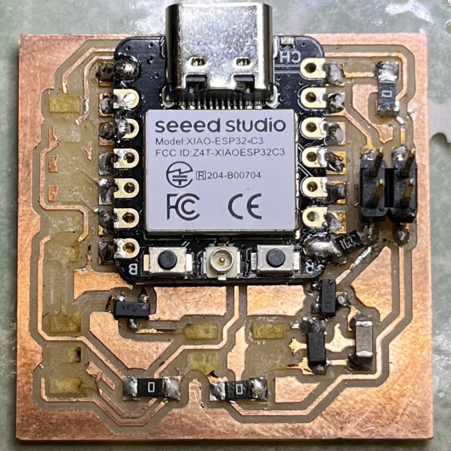
Compared with the board in week 8, the new design eliminated the unnecessary components as described in week 8, added breakout pins for unused pins on the microcontroller board, and changed most of the pins to through-hole types instead of surface mount types to increase the strength. In fact, the primary reason I redesigned and remade the board was that many surface mounted pins on the original board were stripped off accidentally:
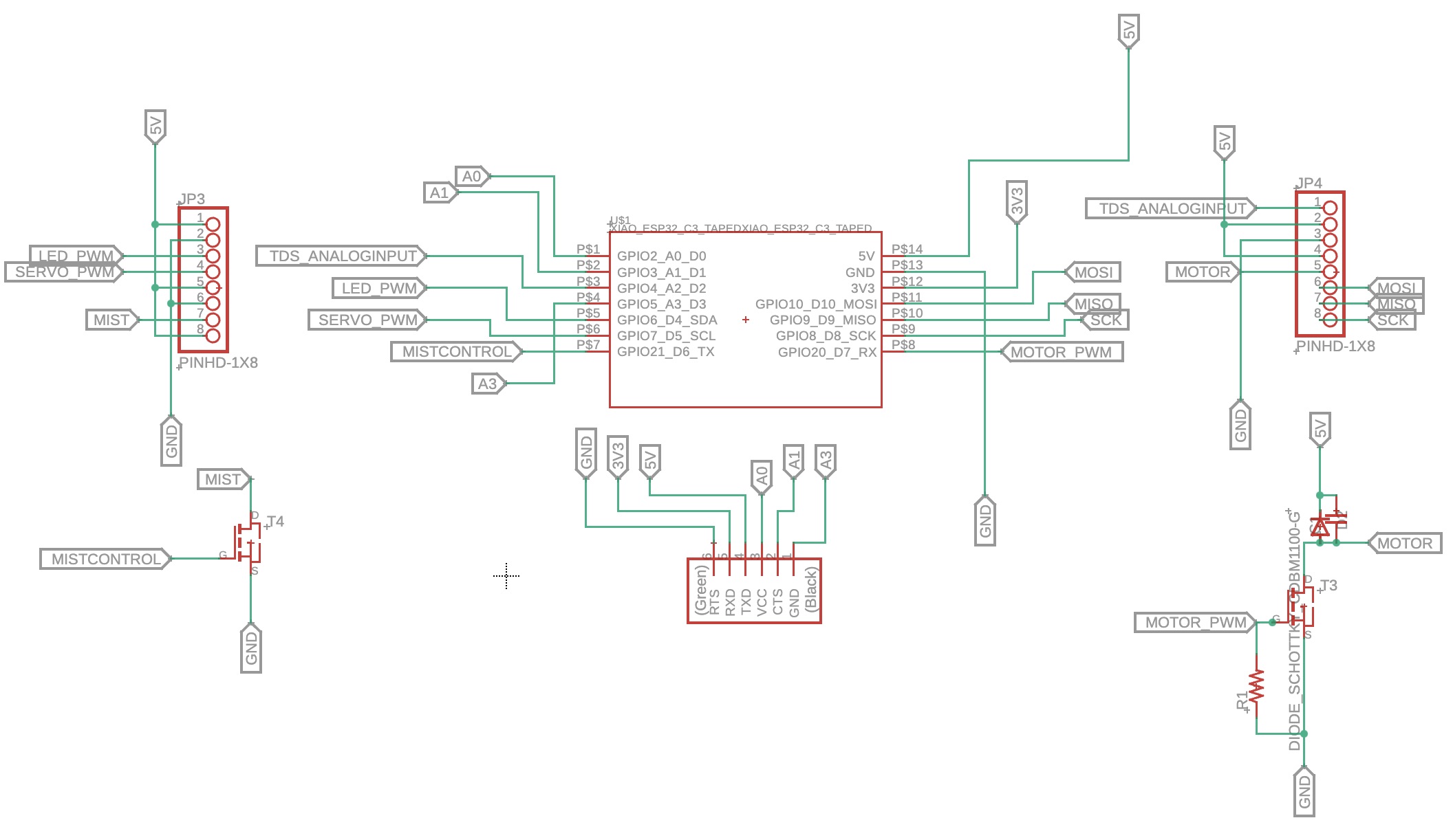
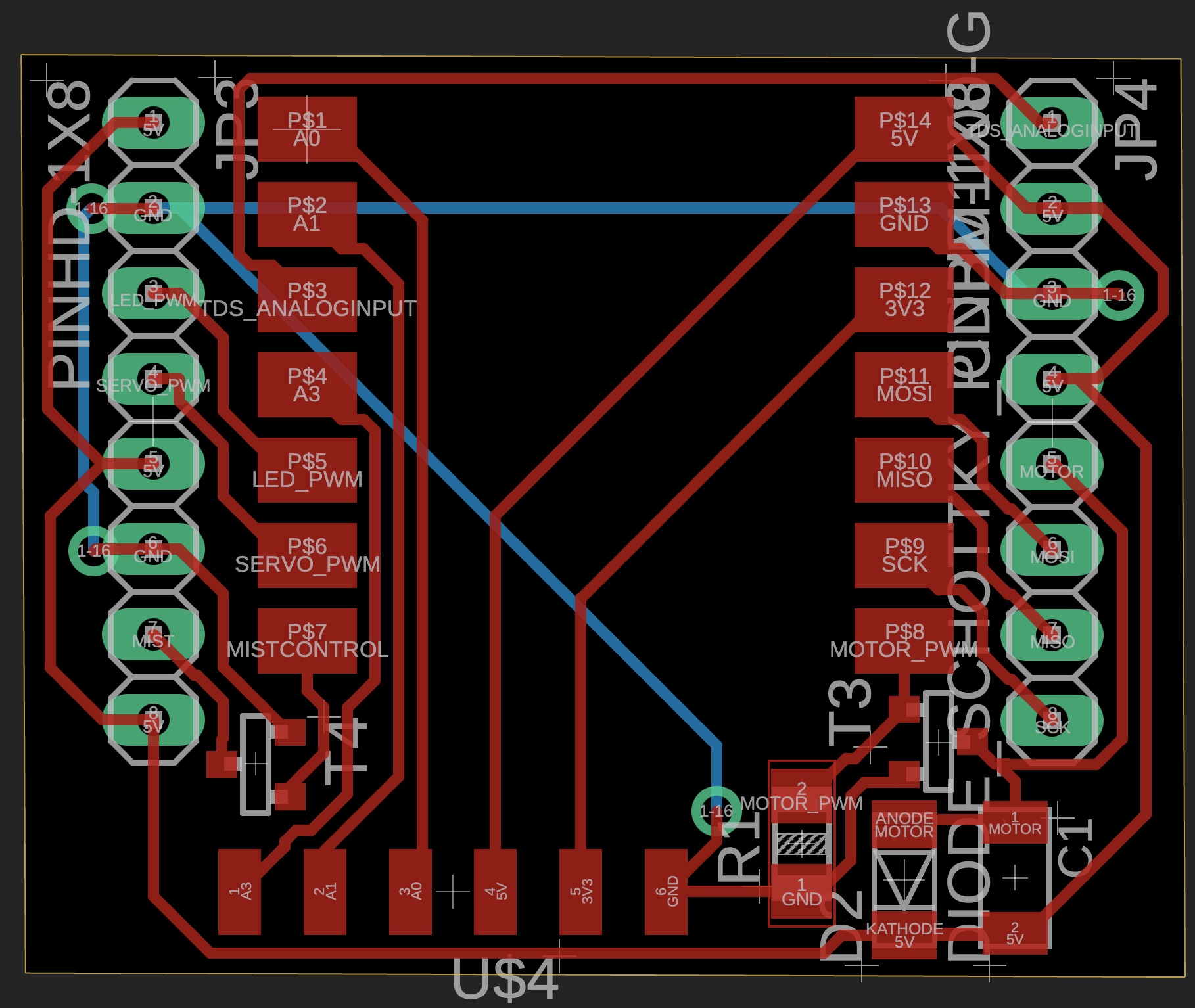
New PCB Schematic and Layout
I like making things compact, and I did not want to solder jumper wires on the board, so I decided to make the board double-sided. With the experience in week 5, I knew I needed to make the through holes larger than 32 mil in diameter for the 0.6 mm rivets to fit in, so this time I made the through holes 39 mil, which turned out to be good, but with some extra space. Next time I may try ~36 mil. Fun fact: the outer diameter measured from the caliper was 0.75 mm (30 mil).
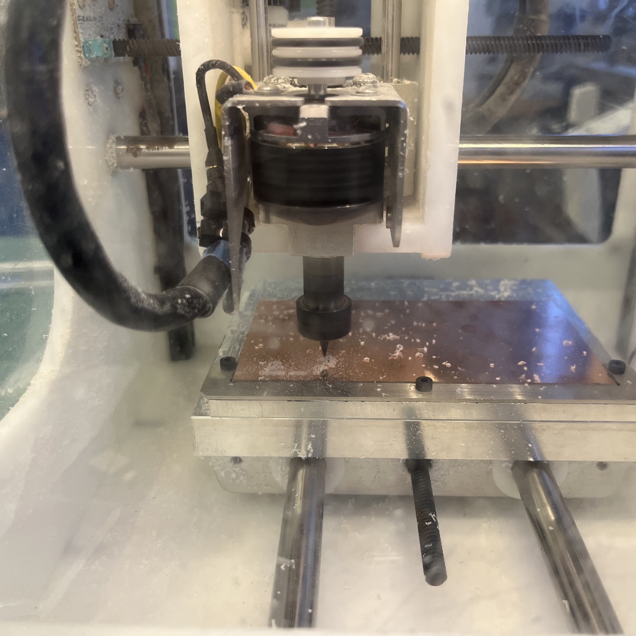
PCB Milling
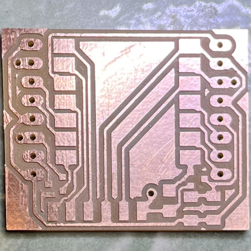
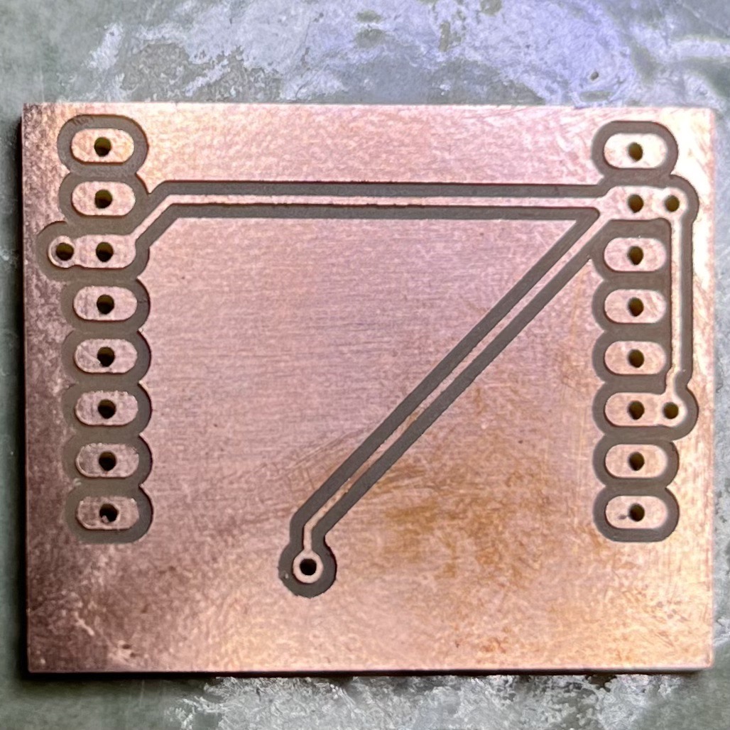
The milling went well as before:
Desoldering XIAO ESP32C3 from the Previous Board
With the aim to reuse the microcontroller board from the previous damaged board, I desoldered it with the help of soldering iron, hot air gun, and hot plate. I also soldered some wires and solder wick on to the two rows of pins, hoping that the heat conduction could be better. It might have helped, but not much. At last, I got one row of pins removed cleanly but the other row stripped the copper traces out. Luckily, I did not need the original PCB board, and the XIAO was not damaged.
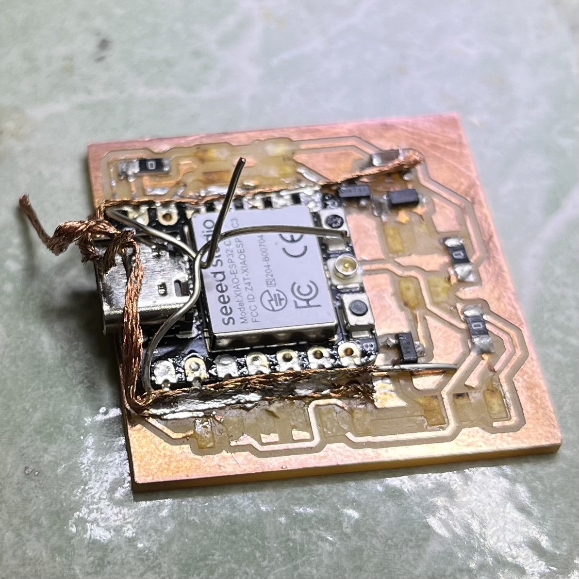
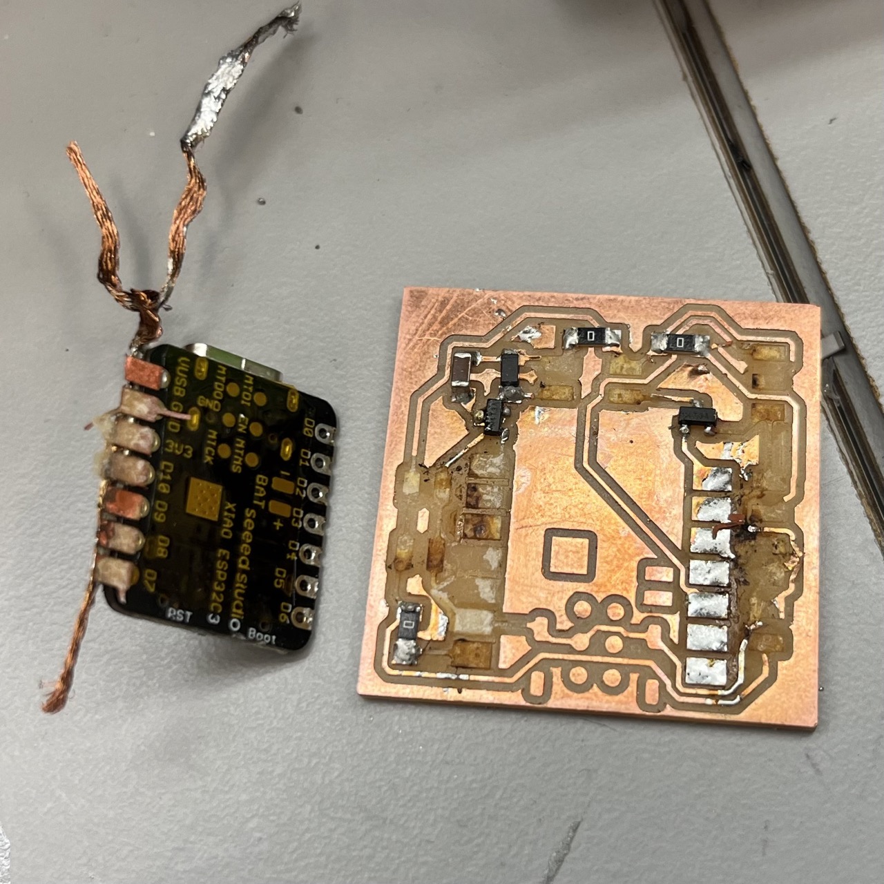
Neil commented later in class that the trick for desoldering was to hold the component with tweezers while flowing hot air around it to let the board drop by gravity. I also realized later that when I was doing the desoldering I did not adjust the hot air flow to be high enough to be effective.
Component Soldering
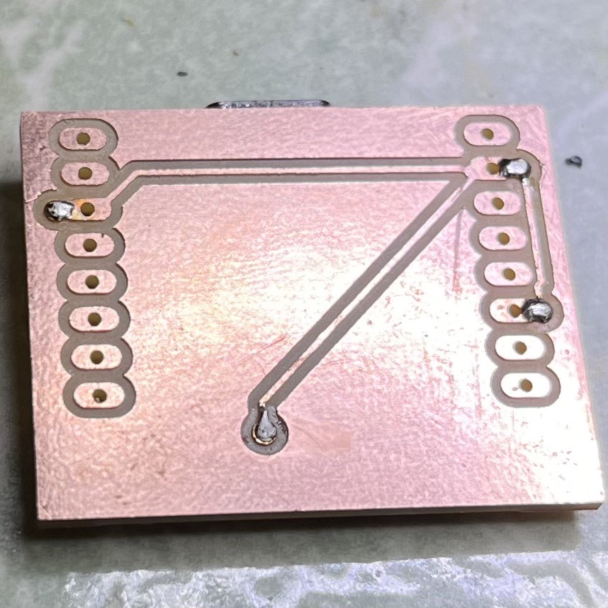
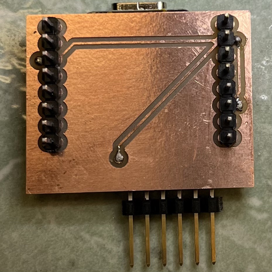
The soldering process was similar to before, except with the addition of rivets. I fitted the rivets in the through holes from one side, flanged them from the other side using a marking punch, and soldered both sides of the rivets to ensure good electrical connection. I used a hammer when flanging, but later I realized it was not necessary, and it could create too much force.
Adding and flanging rivets:
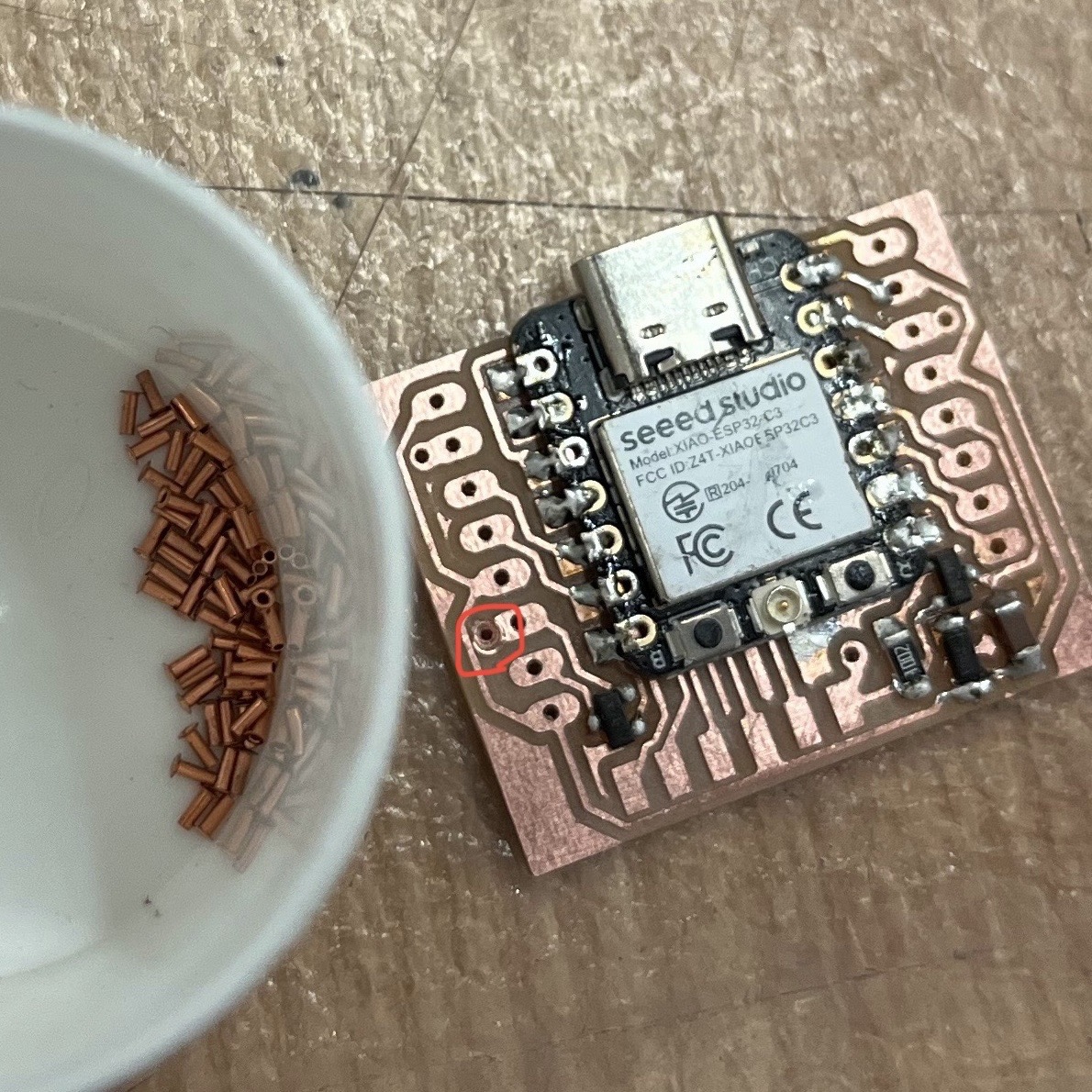
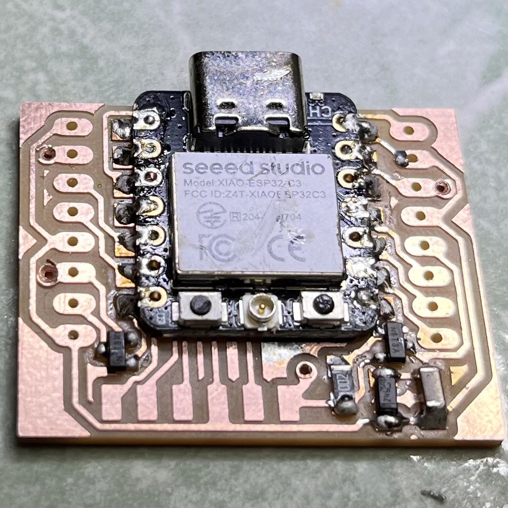
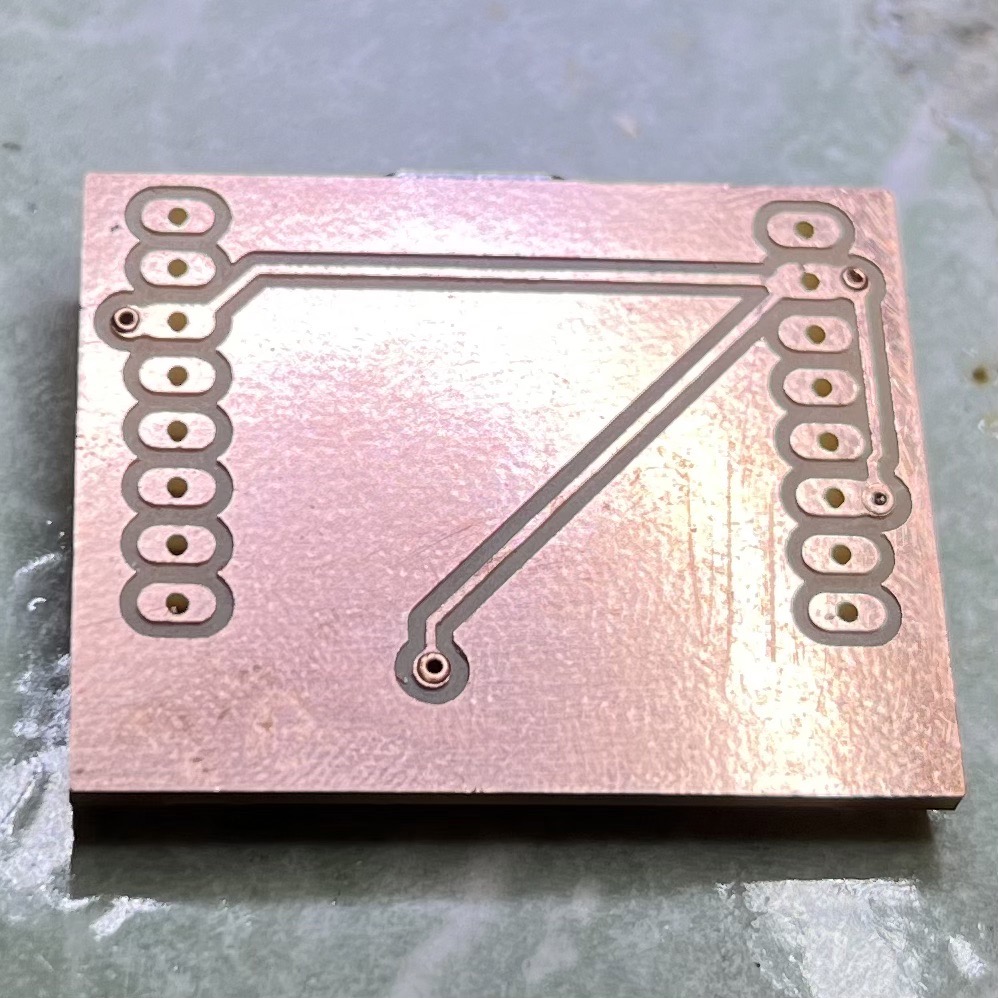
Soldering rivets:
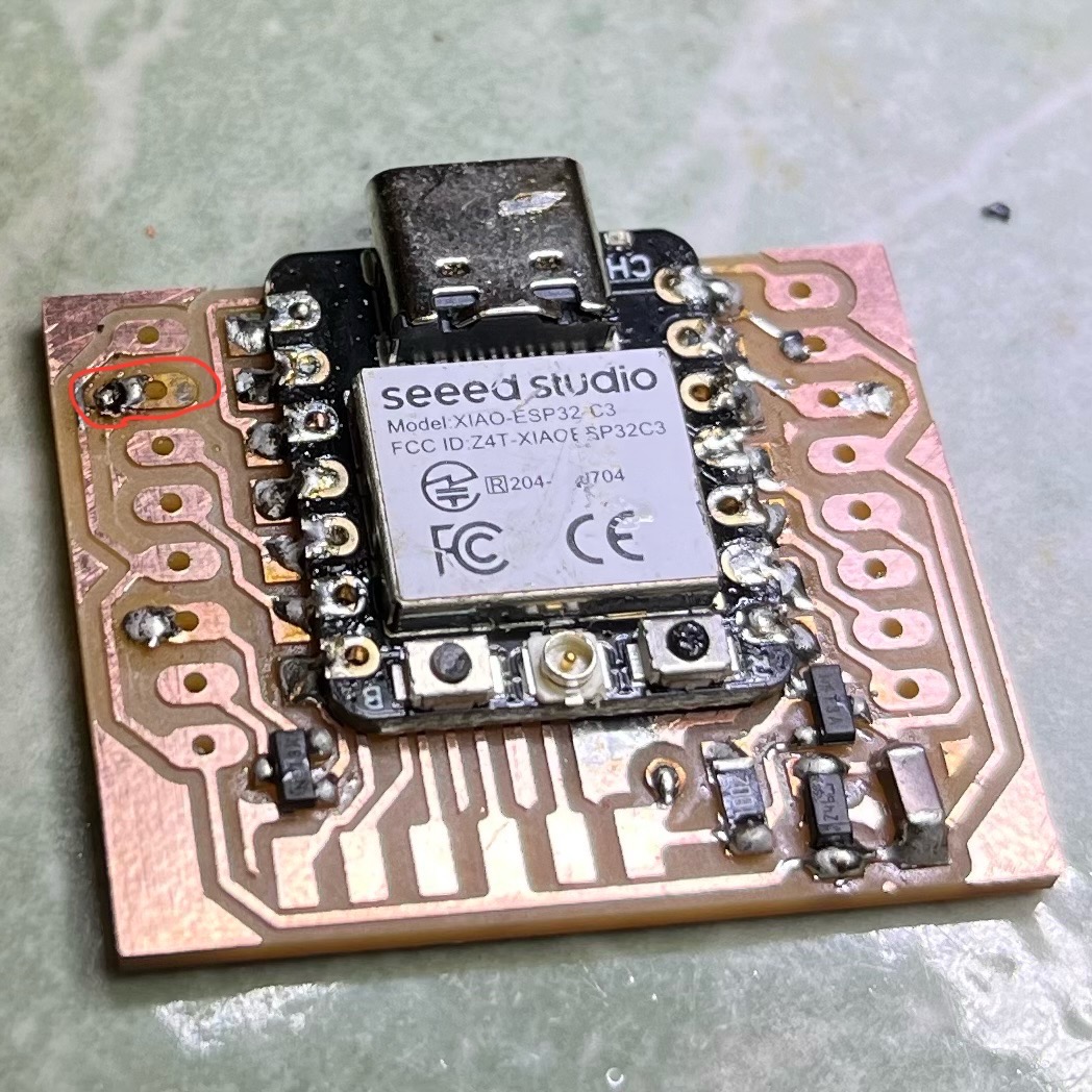
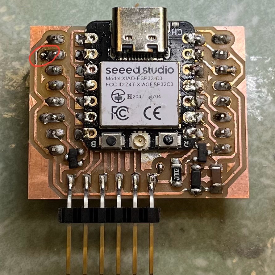
The red circle shows a bad solder joint, which I found with a multimeter and had to fix afterwards.
Soldering pins:
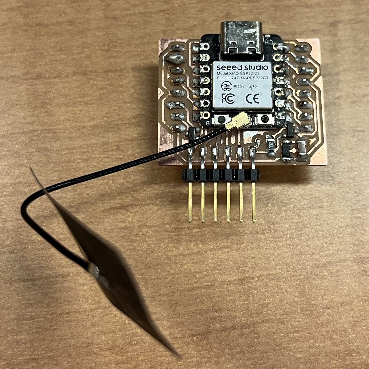
Solder joint fixed and antenna attached:
Board Testing
Code
The code was modified from XIAO ESP32C3 Arduino WiFi example SimpleWiFiServer.ino. It created a WiFi server from XIAO ESP32C3, and clients connected to the server could click the links to turn the motor on and off.
            /*
WiFi Web Server LED Blink

Modified by Fan Xue Nov 2024 to control motor instead of LED

A simple web server that lets you blink an LED via the web.
This sketch will print the IP address of your WiFi Shield (once connected)
to the Serial monitor. From there, you can open that address in a web browser
to turn on and off the LED on pin 5.

If the IP address of your shield is yourAddress:
http://yourAddress/H turns the LED on
http://yourAddress/L turns it off

This example is written for a network using WPA2 encryption. For insecure
WEP or WPA, change the Wifi.begin() call and use Wifi.setMinSecurity() accordingly.

Circuit:
* WiFi shield attached
* LED attached to pin 5

created for arduino 25 Nov 2012
by Tom Igoe

ported for sparkfun esp32
31.01.2017 by Jan Hendrik Berlin

*/

#include <WiFi.h>
const char* ssid = "MIT";
const char* password = "xxxxxxxxxxxx";


NetworkServer server(80);

void setup() {
    Serial.begin(115200);
    pinMode(20, OUTPUT);  // set the motor pin mode

    delay(10);

    // We start by connecting to a WiFi network

    Serial.println();
    Serial.println();
    Serial.print("Connecting to ");
    Serial.println(ssid);

    WiFi.begin(ssid, password);

    while (WiFi.status() != WL_CONNECTED) {
    delay(500);
    Serial.print(".");
    }

    Serial.println("");
    Serial.println("WiFi connected.");
    Serial.println("IP address: ");
    Serial.println(WiFi.localIP());

    server.begin();
}

void loop() {
    NetworkClient client = server.accept();  // listen for incoming clients

    if (client) {                     // if you get a client,
    Serial.println("New Client.");  // print a message out the serial port
    String currentLine = "";        // make a String to hold incoming data from the client
    while (client.connected()) {    // loop while the client's connected
        if (client.available()) {     // if there's bytes to read from the client,
        char c = client.read();     // read a byte, then
        Serial.write(c);            // print it out the serial monitor
        if (c == '\n') {            // if the byte is a newline character

            // if the current line is blank, you got two newline characters in a row.
            // that's the end of the client HTTP request, so send a response:
            if (currentLine.length() == 0) {
            // HTTP headers always start with a response code (e.g. HTTP/1.1 200 OK)
            // and a content-type so the client knows what's coming, then a blank line:
            client.println("HTTP/1.1 200 OK");
            client.println("Content-type:text/html");
            client.println();

            // the content of the HTTP response follows the header:
            client.print("Click <a href=\"/H\">here</a> to turn on the motor.<br>");
            client.print("Click <a href=\"/L\">here</a> to turn off the motor.<br>");

            // The HTTP response ends with another blank line:
            client.println();
            // break out of the while loop:
            break;
            } else {  // if you got a newline, then clear currentLine:
            currentLine = "";
            }
        } else if (c != '\r') {  // if you got anything else but a carriage return character,
            currentLine += c;      // add it to the end of the currentLine
        }

        // Check to see if the client request was "GET /H" or "GET /L":
        if (currentLine.endsWith("GET /H")) {
            digitalWrite(20, HIGH);  // GET /H turns the motor on
        }
        if (currentLine.endsWith("GET /L")) {
            digitalWrite(20, LOW);  // GET /L turns the motor off
        }
        }
    }
    // close the connection:
    client.stop();
    Serial.println("Client Disconnected.");
    }
}
Video Demo
The microcontroller board here was powered by battery only and the signals were transmitted wirelessly.
One concern was that sometimes the response was delayed for a long time or I had to click the links several times for the command to work. Not sure if it was a WiFi issue or another issue.