Topic Choice: 5-Axis Machining
This week, we had a list of interesting topics that we could choose from:
- 5-Axis High Speed Machining
- Composites
- Digital Crochet Design
- Embroidery
- Glass Substrates
- Large Format Flatbed Cutter
- Laser Micromachining
- Make a XIAO
- Metal Laser Cutting
- Robot Arms
- Sketch to Object
- Waterjet
Thinking that my final project would need a propeller, which could be a great example for demonstrating the 5-axis machining capabilities, I chose the first topic, and decided to machine a propeller.
Materials/Components
- Aluminum block (~2.5''x2.25''x11')
Machines/Tools
- 5-Axix CNC mill: Hurco VMX42SRTi
- Circular saw
- Standing drill press
- 1/2'' flat end mill
- 1/4'' flat end mill
- 1/8'' ball end mill
- 5 mm drill
- Dremel rotary tool kits
Software Platforms
- CAD & CAM: Autodesk Fusion 360
Helpful Resources
Design Files
- CAD & CAM: f3z download
Training
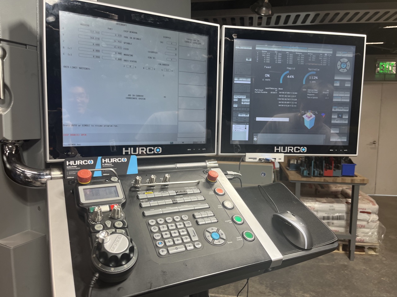
The Hurco VMX42SRTi 5-axis milling machine is a huge machine located at the MIT CBA workshop. Besides the usual x, y, and z axis, the machine bed can spin 360° freely, and the tool head can tilt +/- 92°, making undercuts possible. The machine can be operated form a dual-screen console that has a text screen and a graphics screen, with tool path simulations built in.
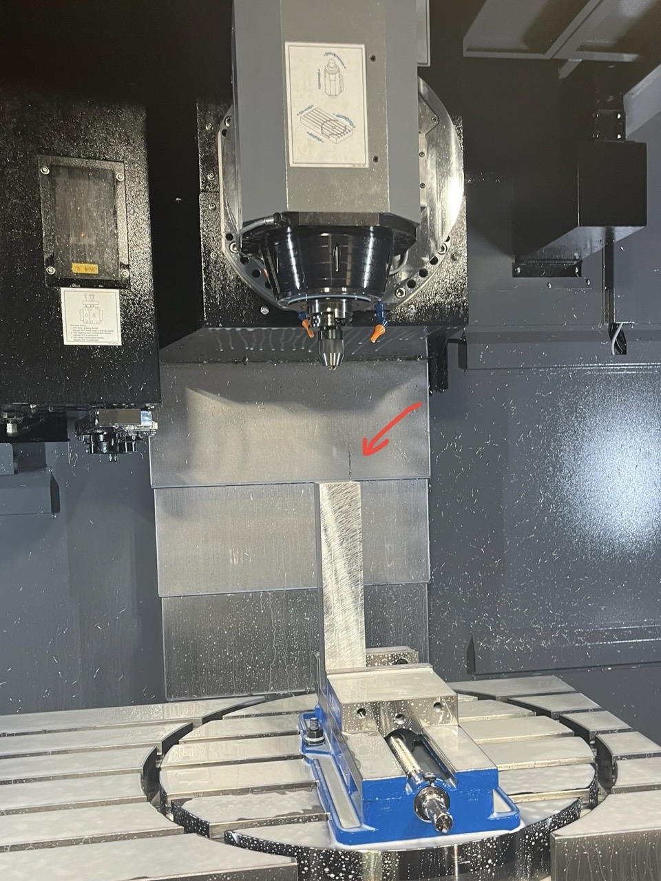
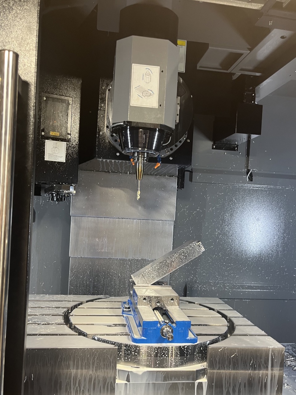
It was super exciting to see the machine in person, but the machine was newly set up, and unfortunately no one was very familiar with it. Some incidents happened during the training: the tool holder got stuck in the spindle and couldn't move, a small tool got separated from the spindle and stuck on the stock during machining (left image), and the stock got knocked off by a bigger end mill, causing the tool to break (right image).
CAD
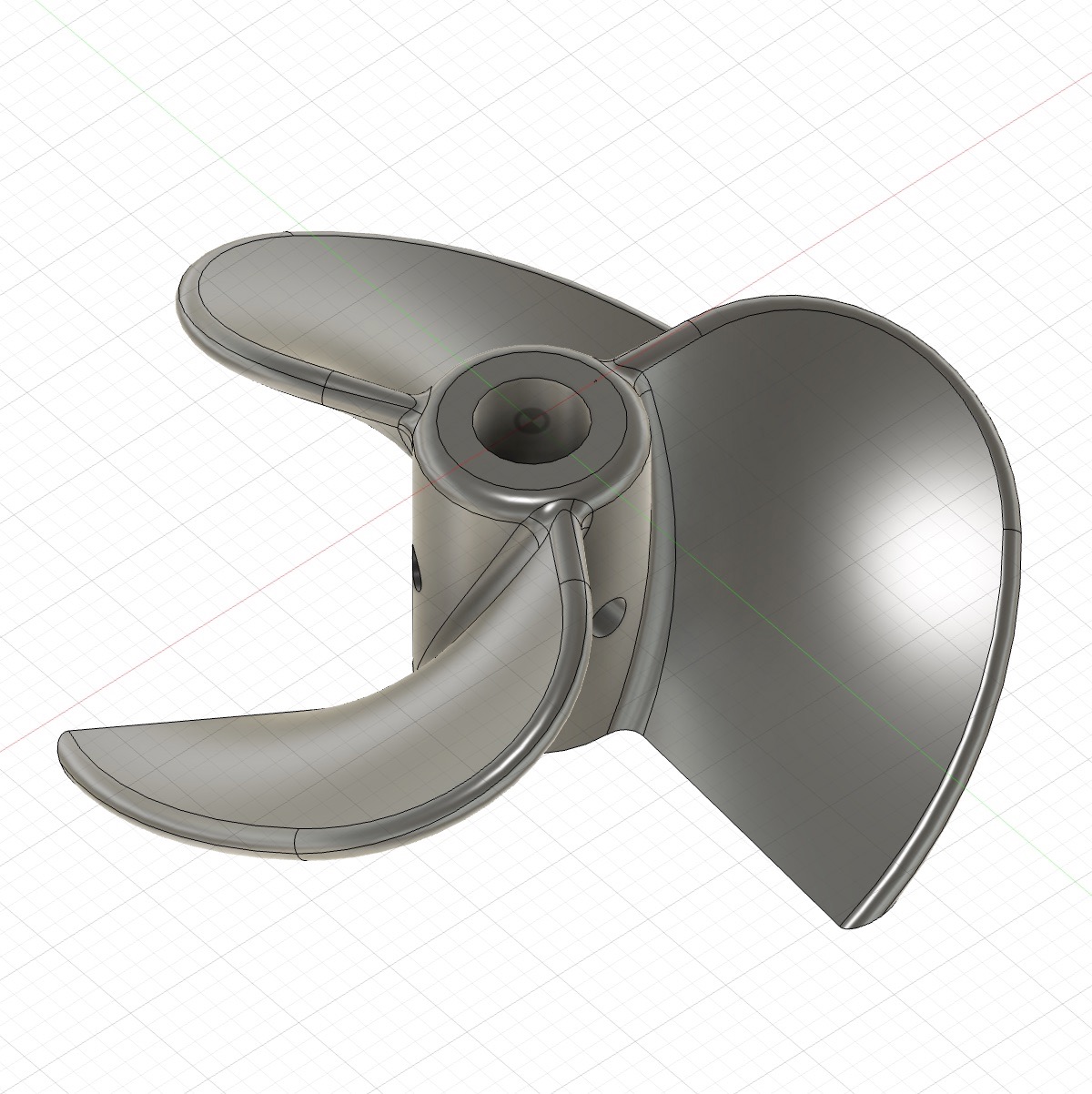
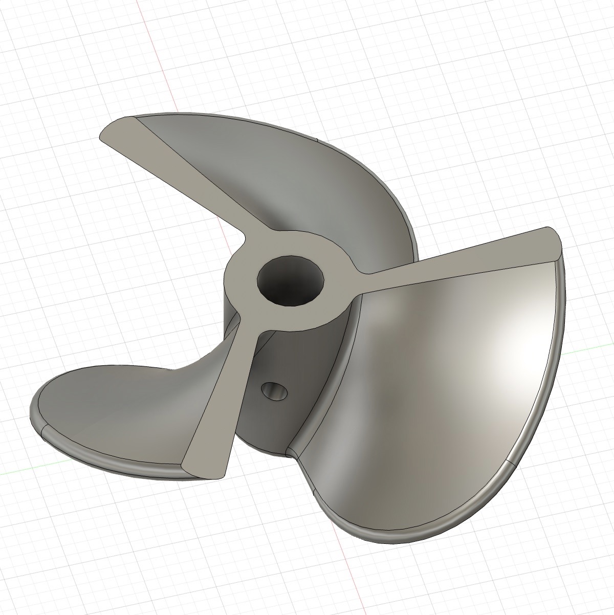
I followed this YouTube tutorial to create a propeller of the size and shape I wanted. I made the one side of the propeller flat, so that machining would be easier. The design is shown below:
CAM
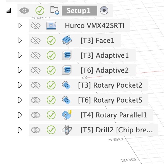
This was my first time doing 5-axis CAM, and unfortunately the support I got was far from what I wanted to do. Below images showed what I was able to figure out this week. The tool numbers shown in the first image below have the following correspondence:
- T3: 1/2 flat end mill
- T6: 1/4 flat end mill
- T4: 1/8 ball end mill
- T5: 5 mm drill
Initially many errors and warnings were coming up, including collisions, rapid move into stock, and overtravel Z. Jiaming helped me give rid of the z-axis overtravel warning by adjusting some machine parameters. Afterwards, I adjusted the toolpaths so that the errors were all cleared.
The available tools were limited, and the 1/8 ball end mill (3'' total length) was the only one that allowed me to reach towards the center without causing collisions. This made me nervous because if I this tool broke, I would have no tool to finish my part, so I tried to clear the parts as much as possible with other tools first before I did the surface finish with the small long ball end mill (although the tool did end up broken as documented below).
Thinking back the rotary pocket with the 1/4'' tool probably did not remove enough material, and causing the rotary parallel to exert too much force on the 1/8'' tool. I believe there were still many other areas for improvements in CAM, which are worth investigating in the future.
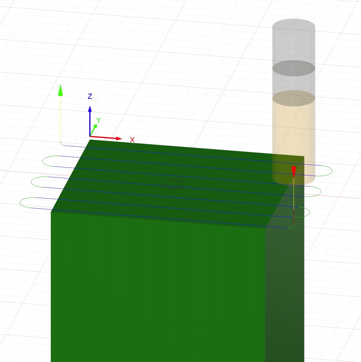
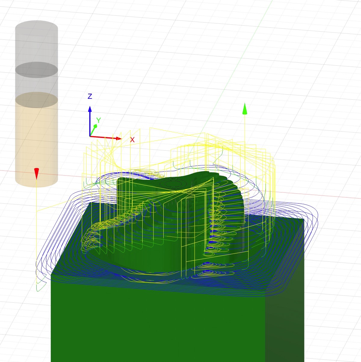
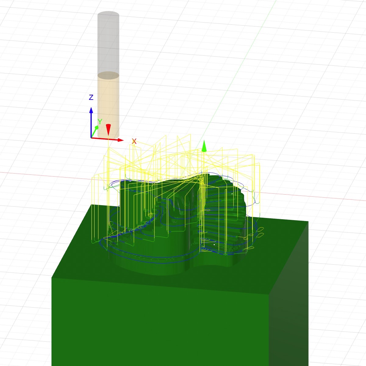
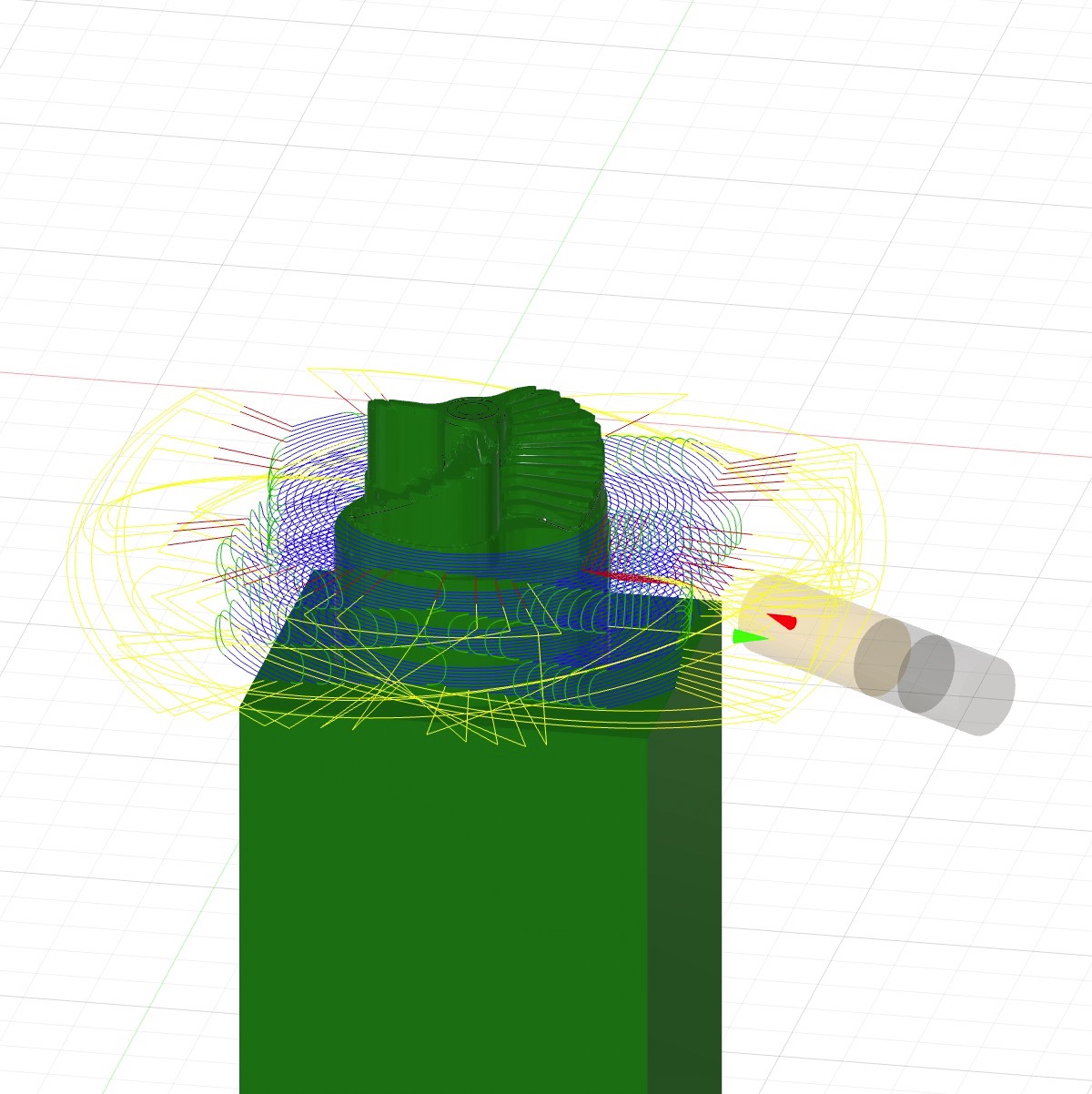
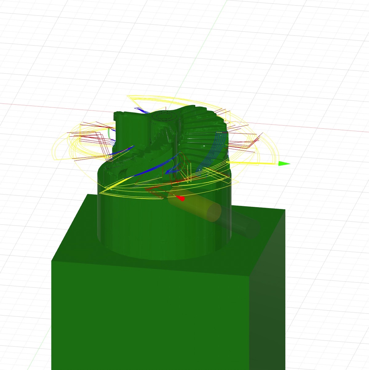
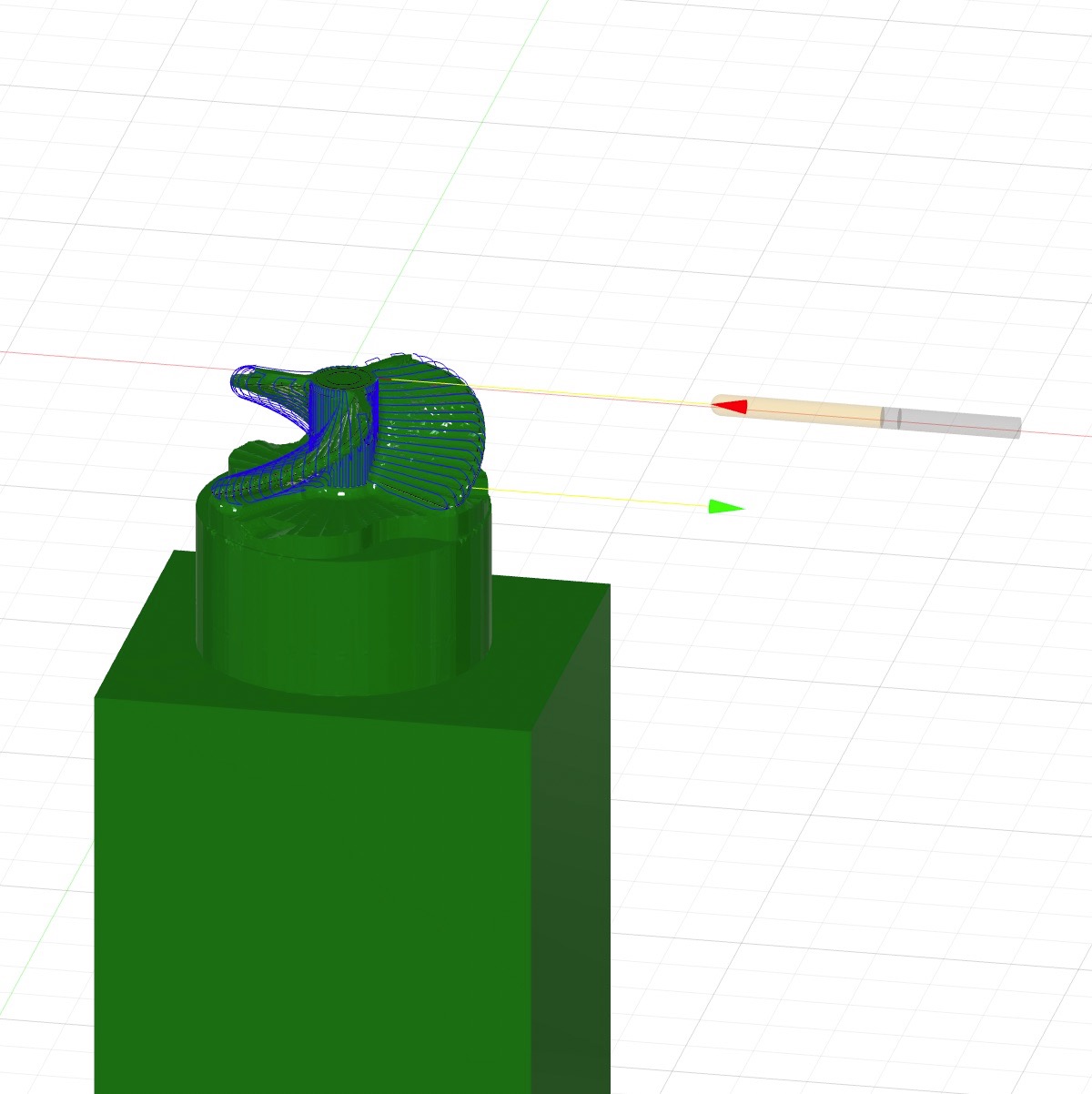
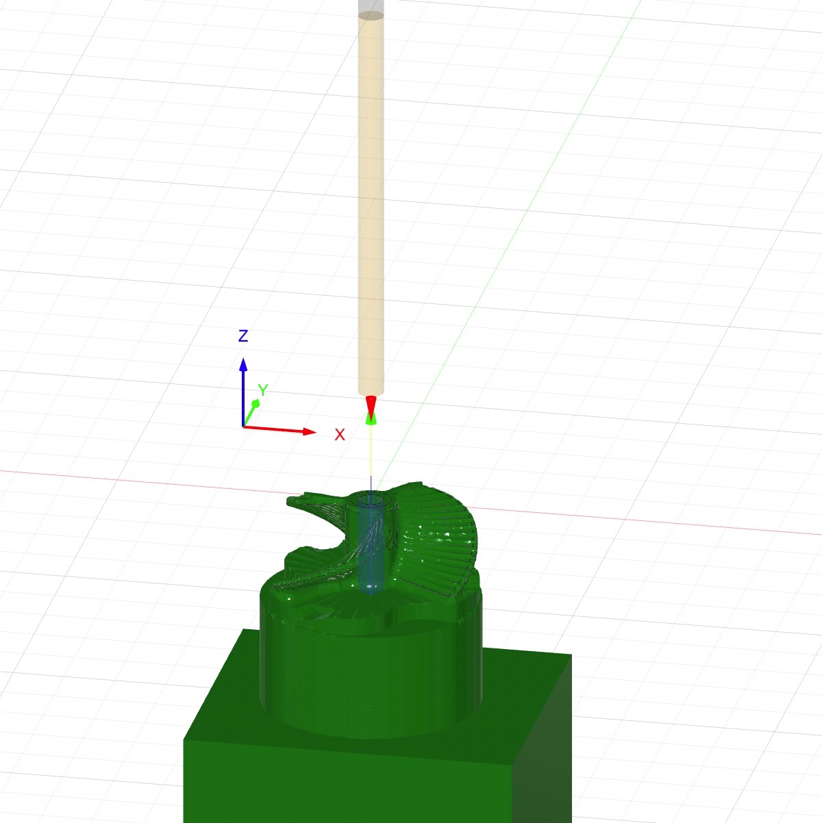
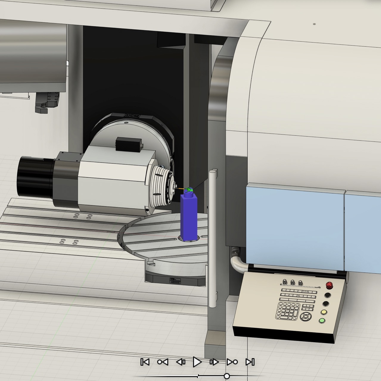
Fusion 360 is very powerful in that it can create toolpath simulation with the machine (image shown below). This helped detect infeasible toolpaths based on machine capabilities and avoid collisions between the machine components and the stock or machine bed. However, the vise holding the stock and the tool holders were not modeled, so extra considerations needed to be made to ensure that they would not collide with anything else. To ensure the tool holder would not collide with the stock, I included a process where I created a neck below the propeller (the 4th toolpath image above) to create some extra space for the tool to reach in. This might be an unnecessary step. In the future, it would be helpful to figure out how to include the tool holder and the vise in the simulation.
Machining
With the help of Marcello, I inserted the tools at the necessary length, loaded them into the spindle, detected tool length, loaded the tools into the magazine at the correct tool number, clamped the stock with the vice on the machine bed, detected the stock's x, y, and z positions with a ruby probe, loaded the G-code generated from Fusion 360, checked the validity of the imported G-code, checked the simulation on the console, and started the cycle. For each toolpath, we started with a slow feed rate and gradually increased it.
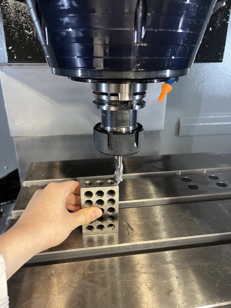
The automatic detection of tool lengths had not been set up, so we had to manually set the z=0 point by having the tool slightly touching a 1''x2''x3'' block.
Below are videos showing machining from the top, from the side (90°), and tool changing and head tilting.
The 1/8'' tool broke when it was doing surface finishing, and since we did not have a replacement tool, and the machining time was limited, I ended up with an unfinished part:
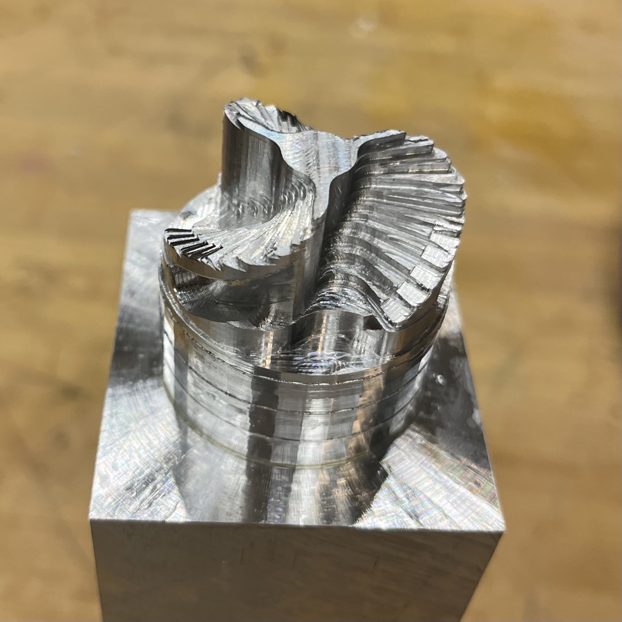
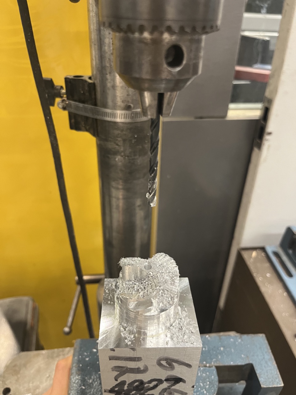
I manually drilled a hole using the 5 mm drill bit with a drill press, and cut the part apart from the stock using a circular saw.
Product Finishing
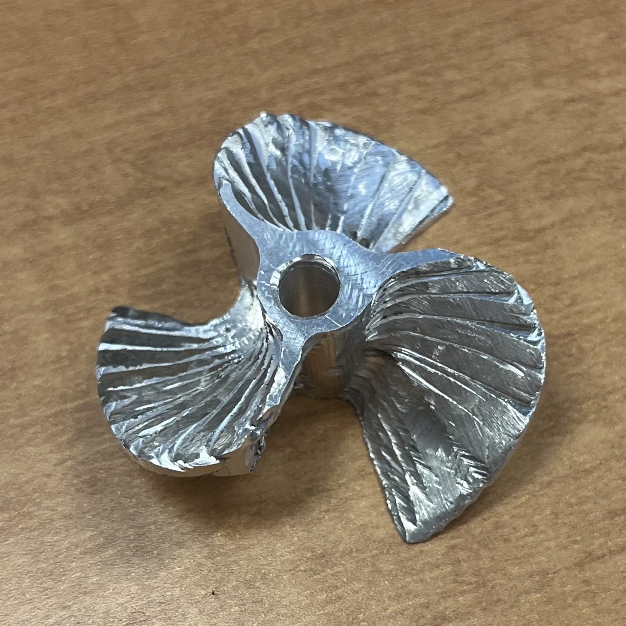
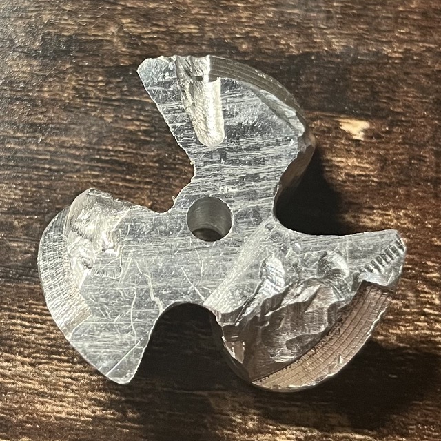
With the help of Dan, I tried to remove the excessive material left on the part using a belt sander and some Dremel tools, but the progress was very slow and it was taking too much time. Eventually I gave up and this was what the final product looked like:
Acknowledgements
This was a tough week, but I would like to thank Marcello for letting me explore the capabilities of the machine and for devoting his time in training and helping us machining. I also wanted to thank Jiaming for providing some valuable insights on CAM, and Dan for helping me with part finishing.