A Steam Boat Water Quality Monitor
Design Idea
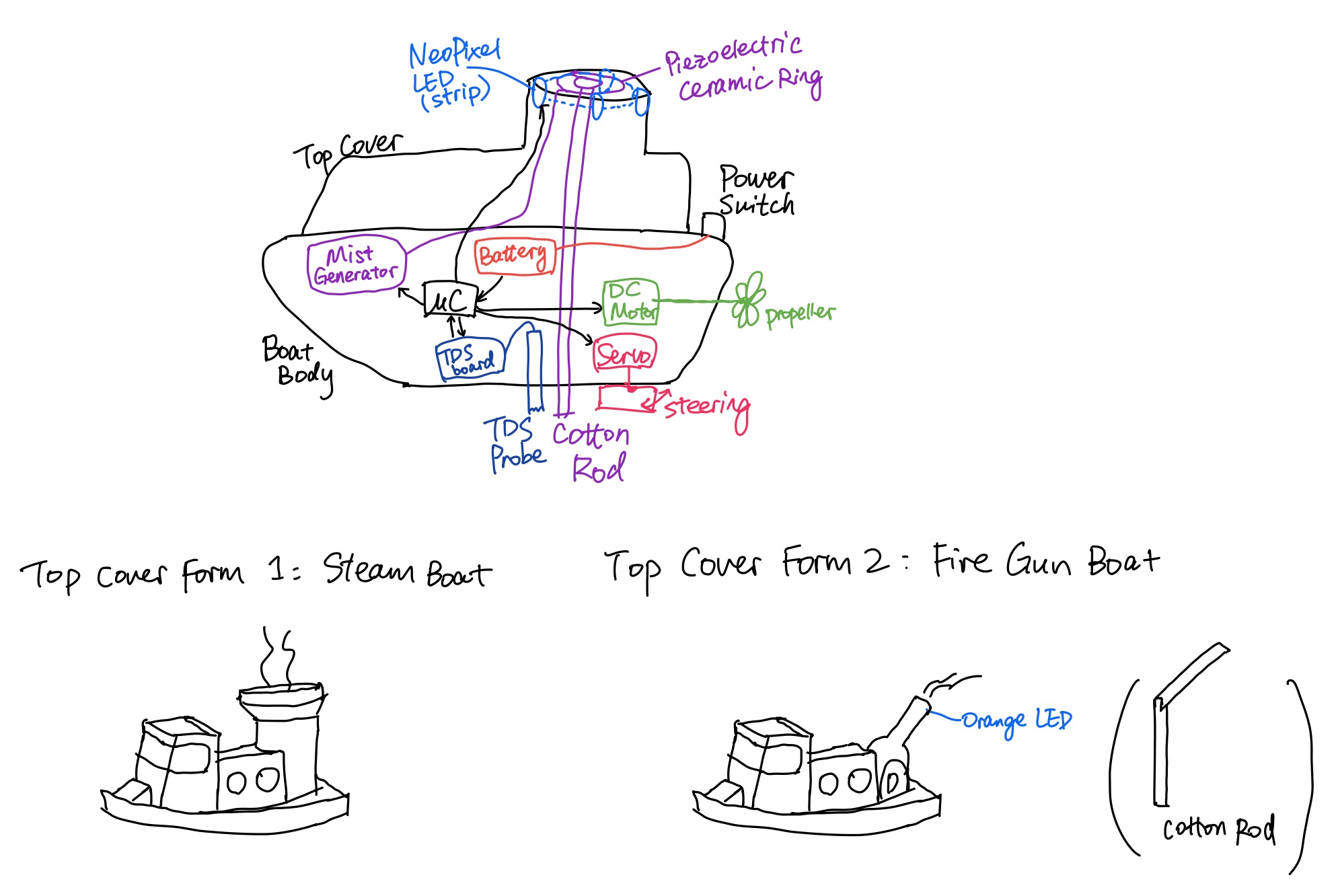
A small RC boat that can move around a pond, measure the water quality, and produce steam that changes colors according to the water pollution level. Several effects can be achieved: "smoke" (white LED), "blue flame" (blue LED) "poisonous gas" (green LED), and "on fire" (red LED). When sitting still on water, the boat can simply function as a household humidifier.
The image below shows the sketch during planning stage. See the CAD section below for the actual design.
Inspirations and Other People's Work
Materials/Components
| Microcontroller board | Seeed Studio XIAO ESP32C3 | $5 (in stock) |
|---|---|---|
| Servo | MG90S | $2.8 (in stock) |
| 12V DC Motor (originally 3-6V 130 DC motor) | L_3FN | $15 (in stock) |
| 4 NeoPixel LEDs | WS2812B | $1.2 (in stock) |
| TDS sensor | SEN0244 | $12 |
| Mist generator/ultrasonic water atomizer | SJ62X4-No Switch | $10 |
| 5V battery (power bank) | Miady 5V/2.4A small portable charger | $9 (in stock) |
| 5 mm rotary shaft | 1327K511 | $5.58 |
| 3 rubber sealed ball bearings | 625-2RS | $3.3 |
| Single-sided copper board | FR1 single-sided | $1.6 (in stock) |
| Double-sided copper board | FR1 double-sided | $1.8 (in stock) |
| 3D-printing filaments | PLA (white), PLA + wood (brown) | - |
| Acrylic for laser cutting | 3 mm thickness, grey colors | - (in stock) |
| Epoxy coating | Smooth-on XTC-3D™ | $8 (in stock) |
| UV glue | Bondic UV resin glue | - |
| Other electronic components | MOSFETs and Capacitors | - |
| Falcon tubes 15 mL and 50 mL | - | - |
Machines/Tools
- Othermill desktop milling machine
- 1/32'' flat end mill
- 1/64'' flat end mill
- Solder wire and solder station
- Hot air station with hot air gun
- Bambu Lab X1C 3D printer
- Universal laser cutter 60 watt
- High-temperature hot glue gun and hot glue sticks
- Dremel rotary tool kits
- DeWALT drill
- Sand paper
Software Platforms
- CAD: Autodesk Fusion 360
- PCB schematic & layout: Autodesk Fusion 360 (EAGLE)
Design Files
- Microcontroller PCB: f3z download
- NeoPixel LED PCB: f3z download
- Boat integration: view/download
- Servo model: source
- Bevel gear models: source
- TDS probe model: source
- USB-A connector: source
- 3-6V 130 DC motor model (abandoned in final product): source
Code
- For webpage: html download
- For microcontroller: ino download
CAD
Overall Design
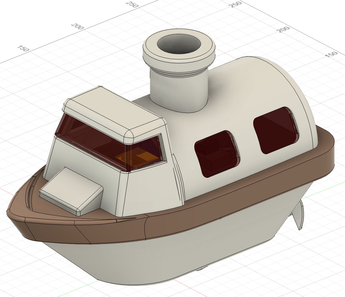

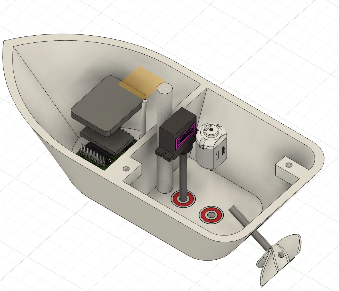
The boat had a boat body at the bottom, a top cover with chimney and decorations, and a middle cover in between. The boat body held the microcontroller board, the mist generator board, the TDS meter board and probe, a cotton rod for transferring moist up to the piezoelectric ceramic ring in the chimney, a rudder, a propeller, and the motion transfer components from the servo/DC motor to the rudder/propeller. The middle cover held the 5V battery, a power switch, and contained holes for wiring and clamping the servo/DC motor. The top cover had a chimney with the piezoelectric ceramic ring holder and the LED board. The windows were flat and were later fabricated with laser cutting acrylic sheets. There was also a power switch cover that sat in front of the top cover and on top of the middle cover.
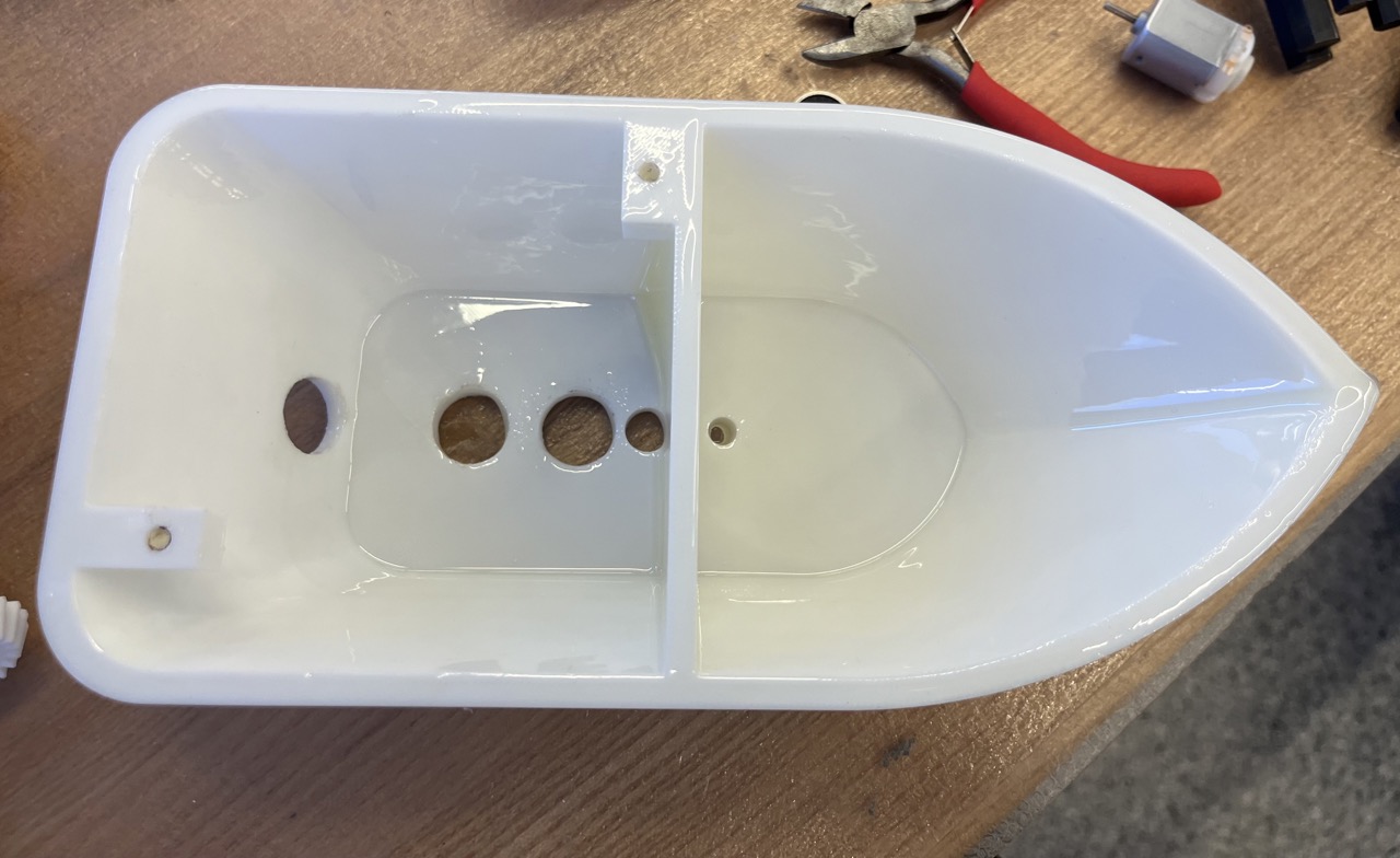
Design Consideration 1: Water Proof
As boats go on water, it would be bad if the electronics in the boat got contact with water. Therefore, I designed the boat body to have two compartments, with one compartment fully sealed from water holding major electronic components, and another compartment connected to the rudder, the propeller, and the cotton rod that went to the piezoelectric ceramic ring for generating mist. The servo and the DC motor were held by a cover that went on top of the boat body, so that they could be protected from water to some degree as well.
Design Consideration 2: Propeller Position and Motion Translation
To translate the motion of the DC motor to the propeller, a pair of bevel gears were used. In an initial design, I used the 90° bevel gears. However, this would result in an unadjustable propeller height, and the propeller position was higher than what I wanted.
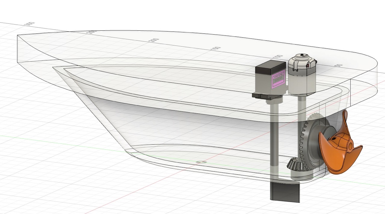
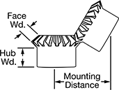
Therefore, in a final design, I changed to 60° bevel gears. Originally, I imported the models from Mcmaster part 6529K58. As I was trying to align the parts in Fusion, I found that the Mcmaster's illustration for mounting distance was incorrect (left). The correct mounting distance (40 mm) illustration could be found in their product drawing (right). In the usual 90° bevel gears, these two illustrations would be showing the same things, but in the 60° one it would be off.
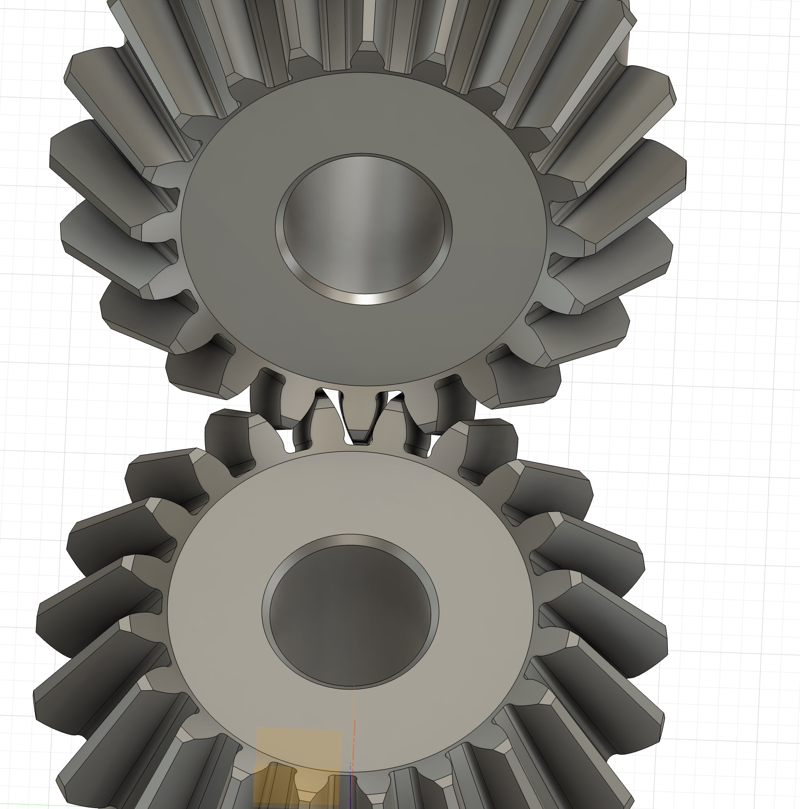
After I aligned the gears with the correct mounting distance, I was surprised to find that the two gears had interference with each other.
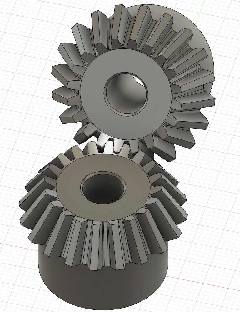
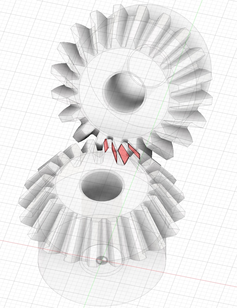
I didn't think the gears would work in this way, so I found another model from Grainger 793D46. This time the gears didn't show interference, and there were still some gaps between the two gears, which would be helpful in my case as I would be 3D printing the gears. It turned out from the 3D printing results that those gaps were not enough, and I had to scale the gears 95% in my final design.
I modified the imported models so that the gears could fit with my purpose. Additionally, to translate the motion from the servo to the rudder, simple shaft coupler designs were used as inspired by Anthony.
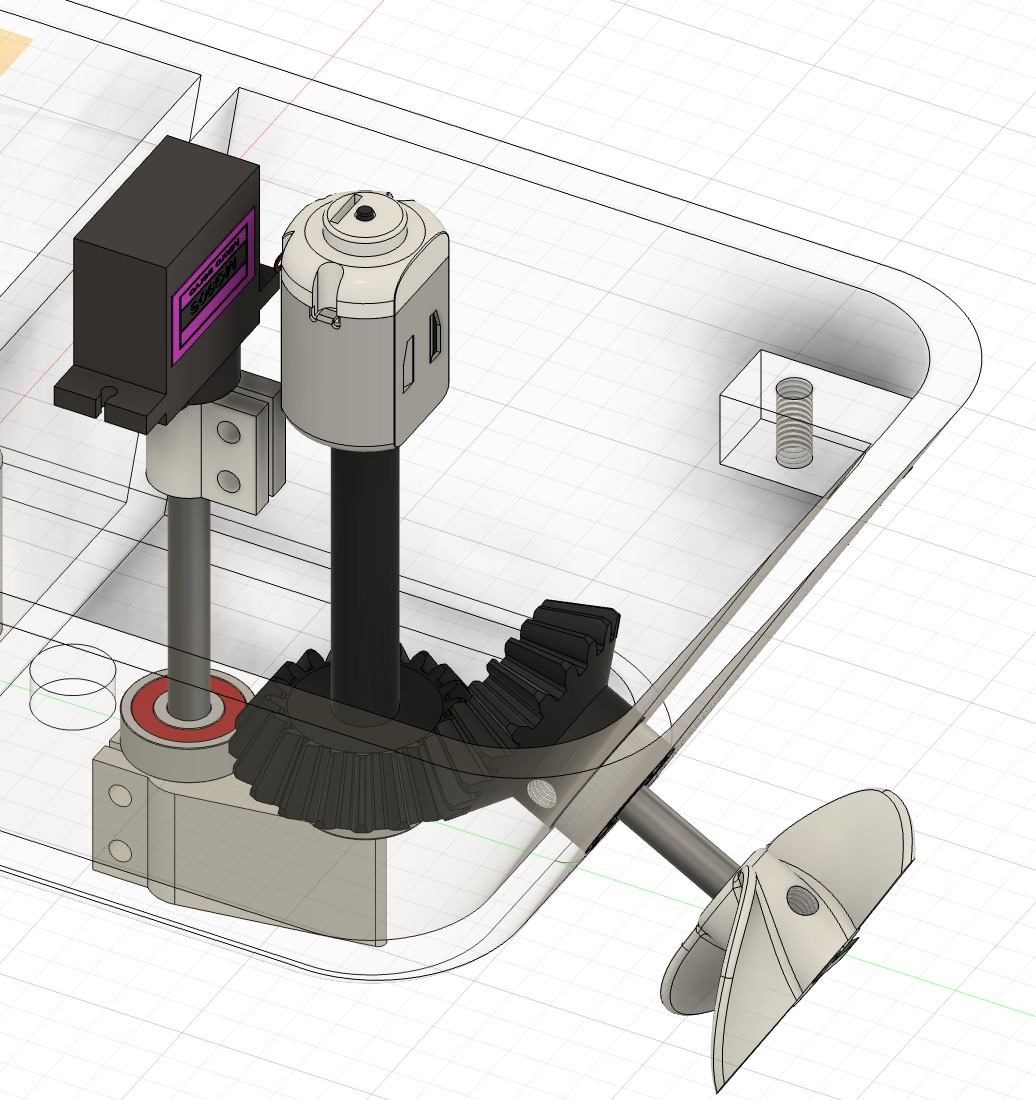
Note: the 130 DC motor in the design was later abandoned because of insufficient torque to drive the motor, and a more powerful motor (L_3FN) was mounted on top of the middle cover with a clamp.
Electronics Design and Production
Microcontroller Board Connecting Input and Output Devices
See week 11.
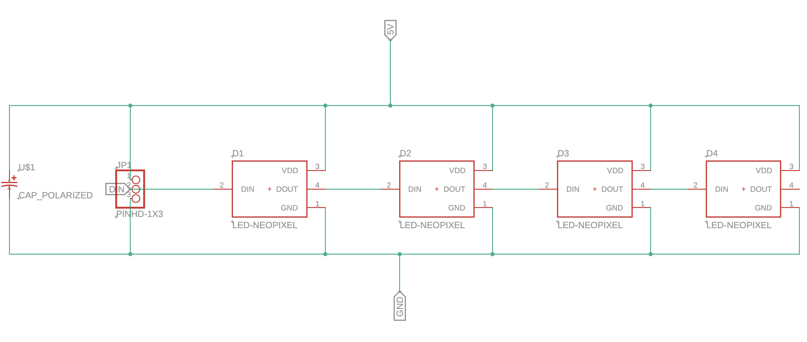
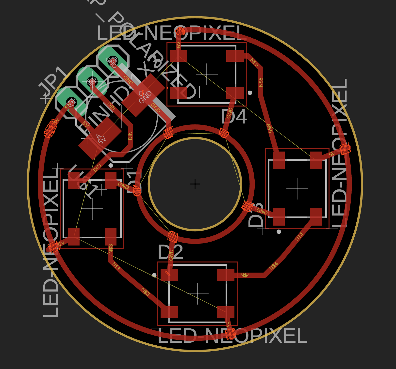
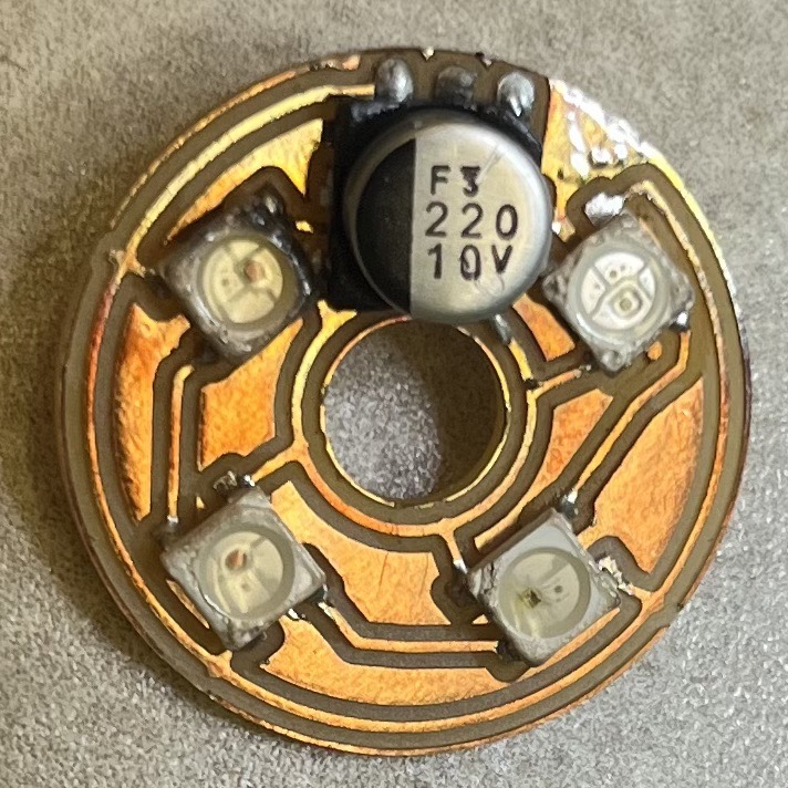
LED Board
Four NeoPixel LEDs were connected in a ring with a 220 uF capacitor connected between 5V and ground to reduce noise the power line. Originally the board was not designed to have a capacitor. However, the board behaved unexpectedly when the microcontroller was controlling the motor simultaneously (see Neopixel LED Testing section below). Below images show the final board schematic, PCB layout, milling process, and the soldered board. The board was a little burnt when I was using the hot air gun to solder the components, but the electrical connections turned out to be fine.

Networking and Interface
The Wifi connections and the webpage UI were established in week 12. The XIAO ESP32C3 was configured as an access point, and communications between the chip and the UI followed WebSocket protocol. Code modifications from week 12 included the color changes according to the TDS values. See NeoPixel LED Testing section below for details.
Testing and System Integration
Electronics Testing (Except NeoPixel LEDs)
See week 12.
NeoPixel LED Testing
All of the NeoPixel LEDs were programed to change colors simultaneously according to the ppm value measured from the TDS meter. In the video below, my fingers were touching the TDS meter pin on the microcontroller to mimic a change in the TDS signal. The color changes were set to go from white to blue to green to red from the minimum TDS value (0 ppm) to the maximum TDS value (arbitrarily set to 500 ppm).
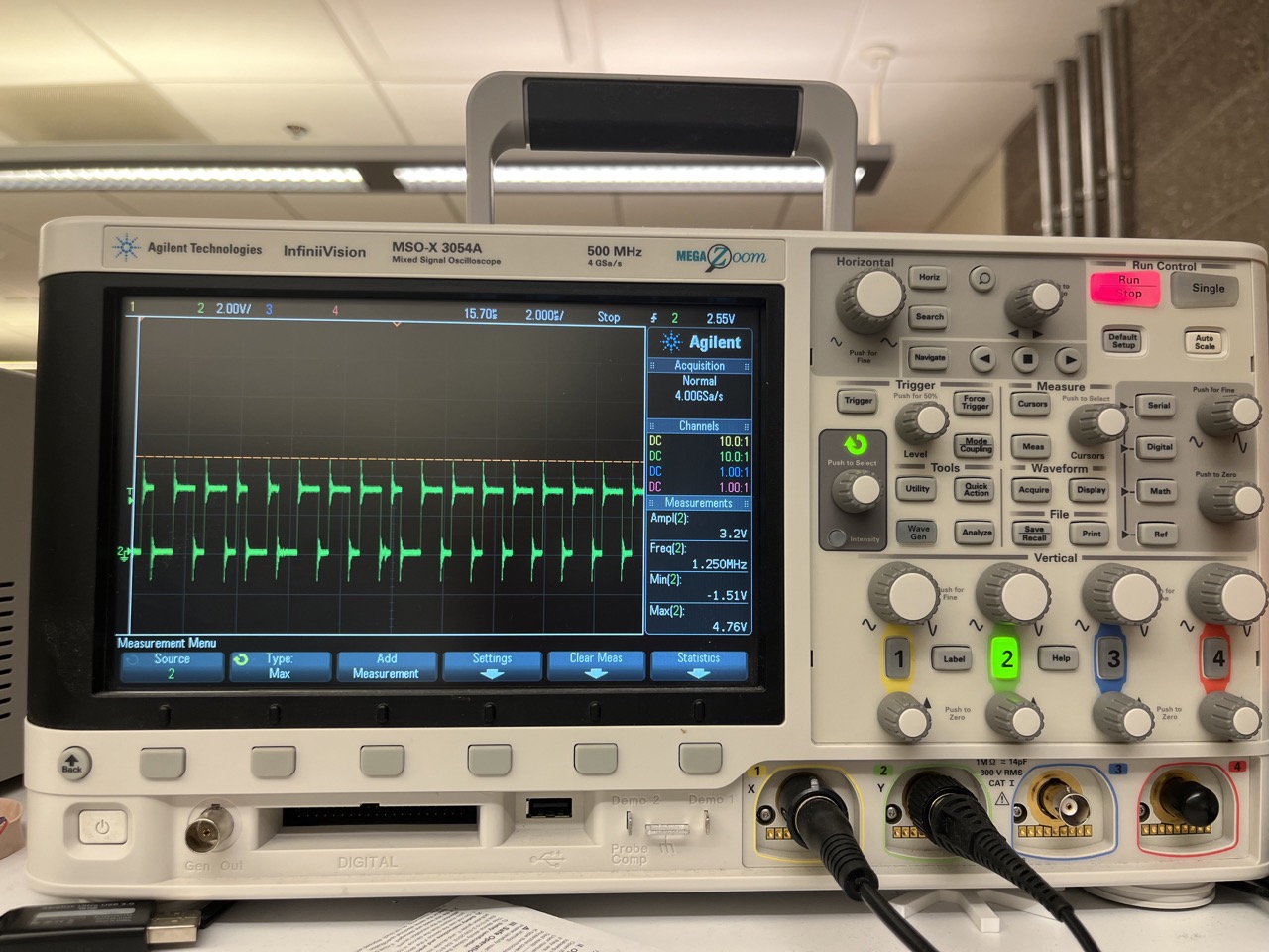
The board shown in the above video did not have a capacitor. We can see that it behaved fine alone. However, whenever I turned the motor on, the LED would automatically switch off or start to blink. Turning on the motor control without physically connecting the motor was fine. Replacing the motor with a power resistor also showed the same problem, which meant that it was not a noise issue, but a power or current issue, as suggested by Anthony.
With the help of Anthony, I checked the waveforms of the 5V, 3.3V, and LED data lines on the oscilloscope. All of them were experiencing spikes.
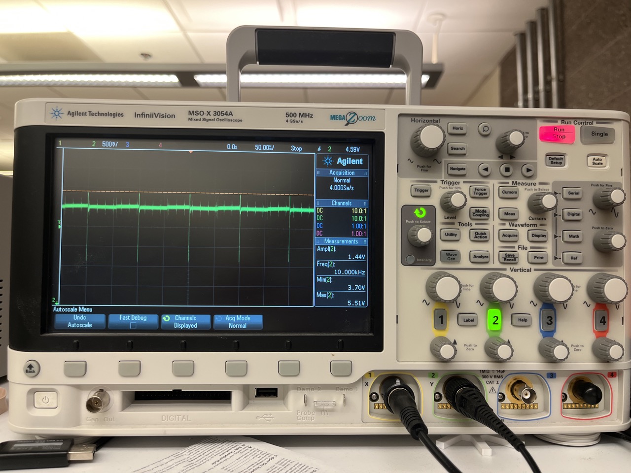
Anthony suggested that I add a big capacitor between the 5V and ground to reduce power line disruptions.
Adding the capacitor near the microcontroller board did not solve the problem, but adding them directly on the LED board solved the problem!
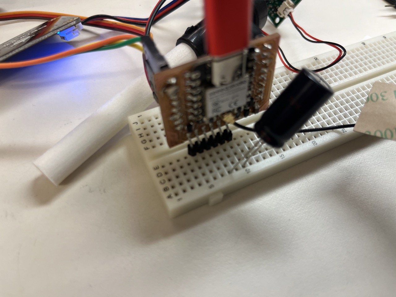

Therefore, I redesigned the board with a surface-mount capacitor, as shown in the LED Board section.
3D printing
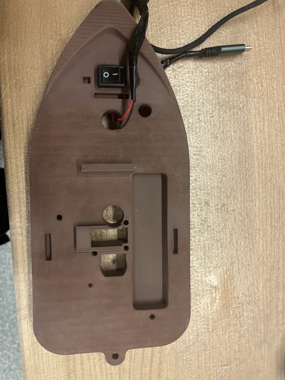
I 3D-printed the middle cover with brown PLA + wood filaments, and the top cover, servo and motor clamps, rudder, propeller, and power switch cover with white PLA filaments on the Bambu printer.
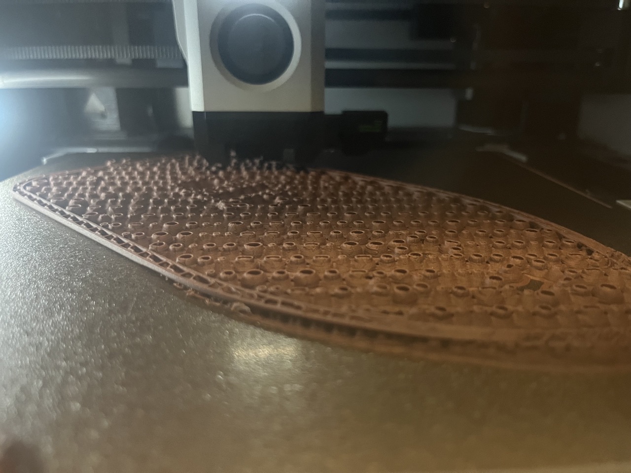

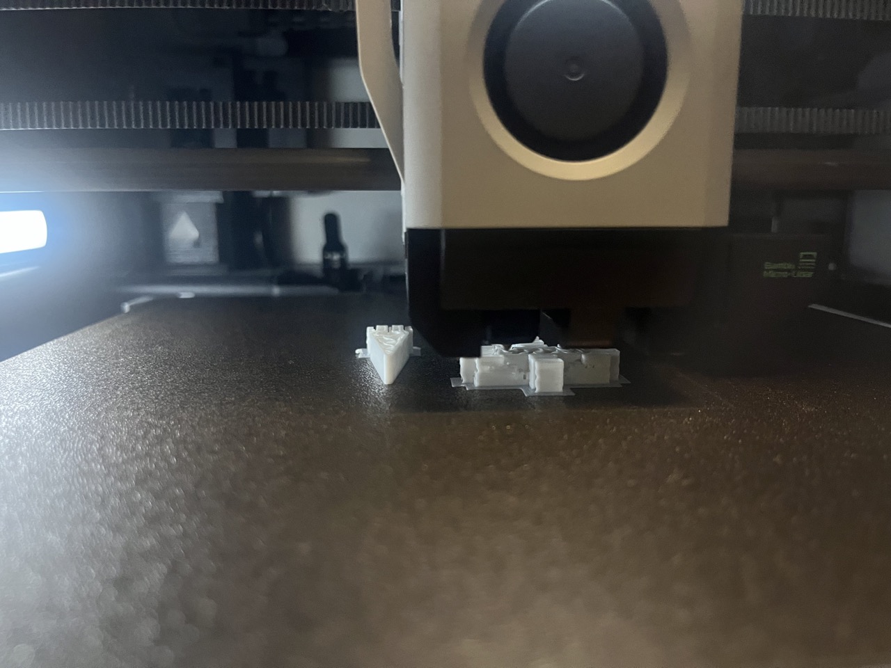

"Organic" or "tree" type support was much easier to remove than the regular/normal support in my case.


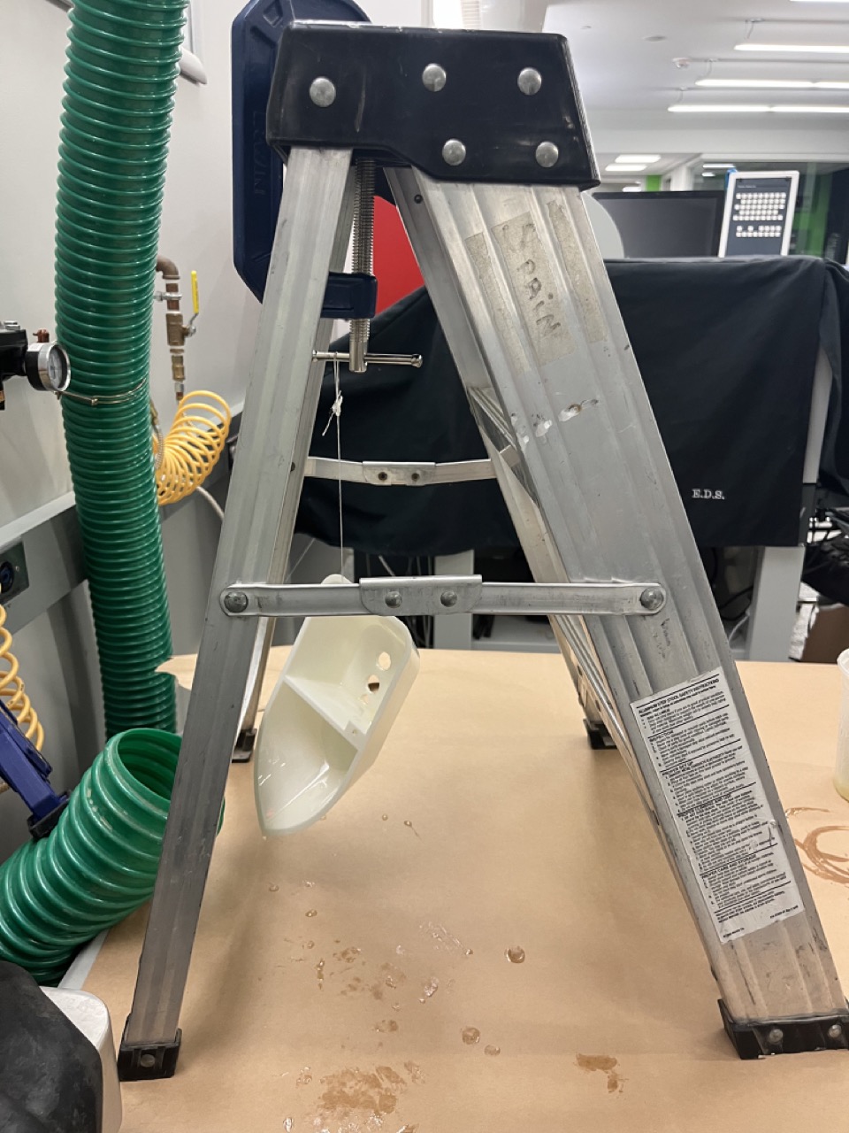
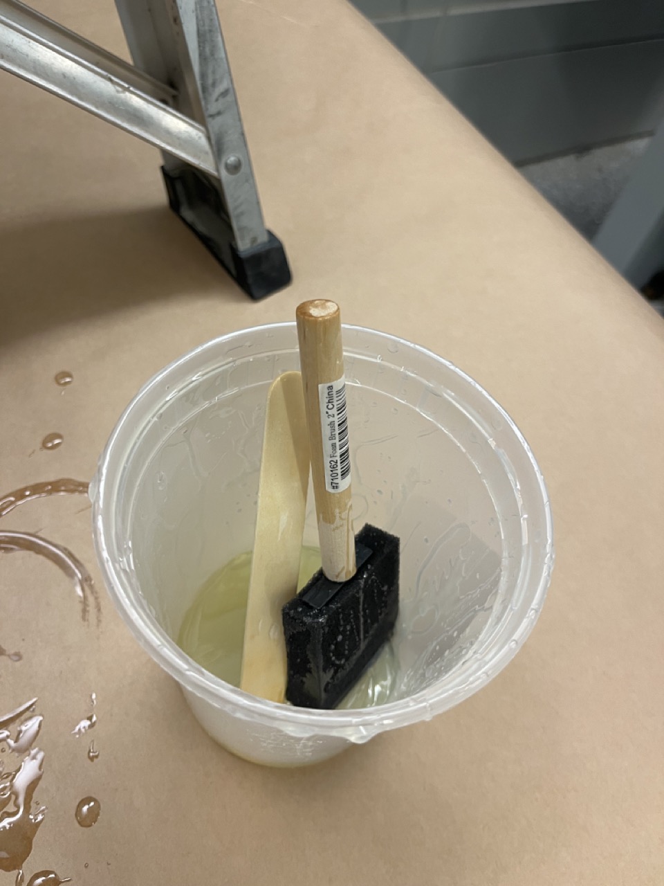
Epoxy Coating
For the boat body to be water proof, I coated a layer of epoxy on the surface using a foam brush with the help of Anthony.
Smoothening Layer Lines
Since the boat middle cover was not flat, some printing layer lines were clearly visible. To remove those lines, I sanded the surface with a Dremel sander bit, and used a hot air gun to darken the surface.

Laser Cutting
I laser cut the windows of the boat with grey acrylic, and used super glue/UV glue to stick the windows on the top cover.
Assembly
The rotary rod was too big to fit in the ball bearings, although their diameters were supposed to match (5 mm). With the suggestion of Anthony, I used the DeWALT drill to hold and rotate the rod while pressing a sand paper to the rod surface to sand the rod.
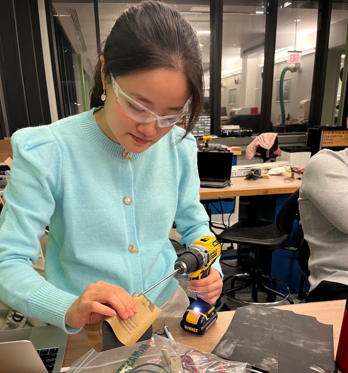
Thank you Sungmoon for taking the picture!
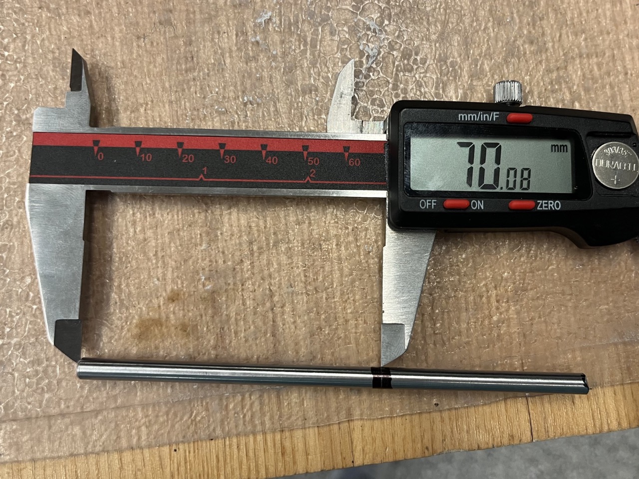
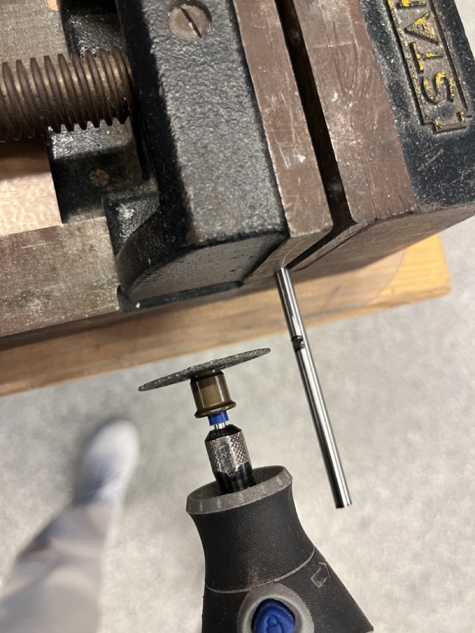
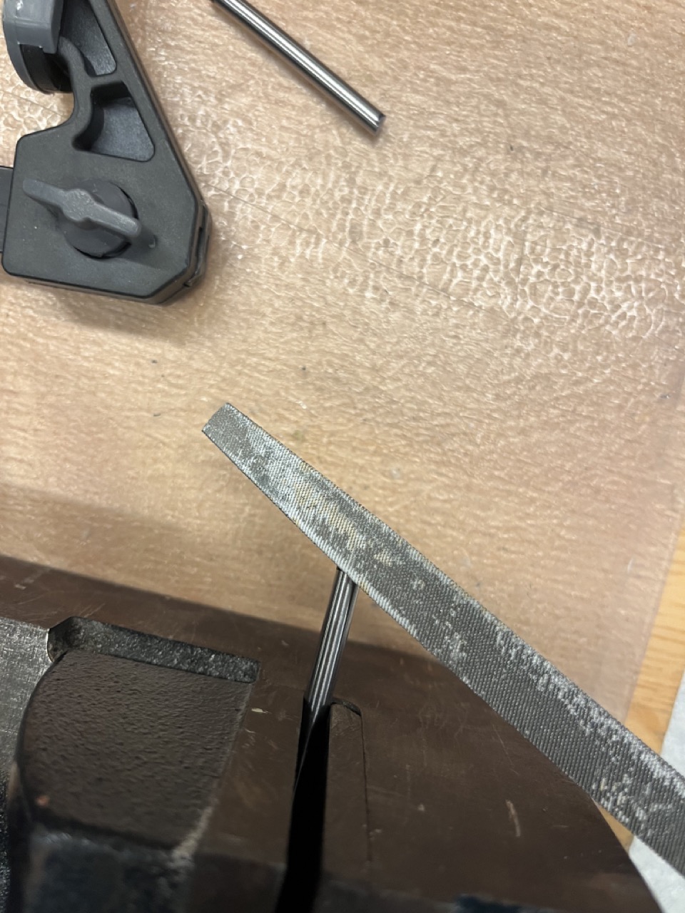
After that, I cut the rod to the right length also with the help of Anthony. A sharpie was used to mark the rough position for cutting and a caliper was used to scratch the sharpie to get a more accurate position. A Dremel cutter was then used to cut through the rod, and a file was used to smooth the rod end.
To seal the ball bearings with the boat body and the rotary rods, I applied UV glue around the edges to be sealed. Unfortunately during the water test, water was still leaking through the rubber seal from the ball bearings, and there was not much we could do about it.
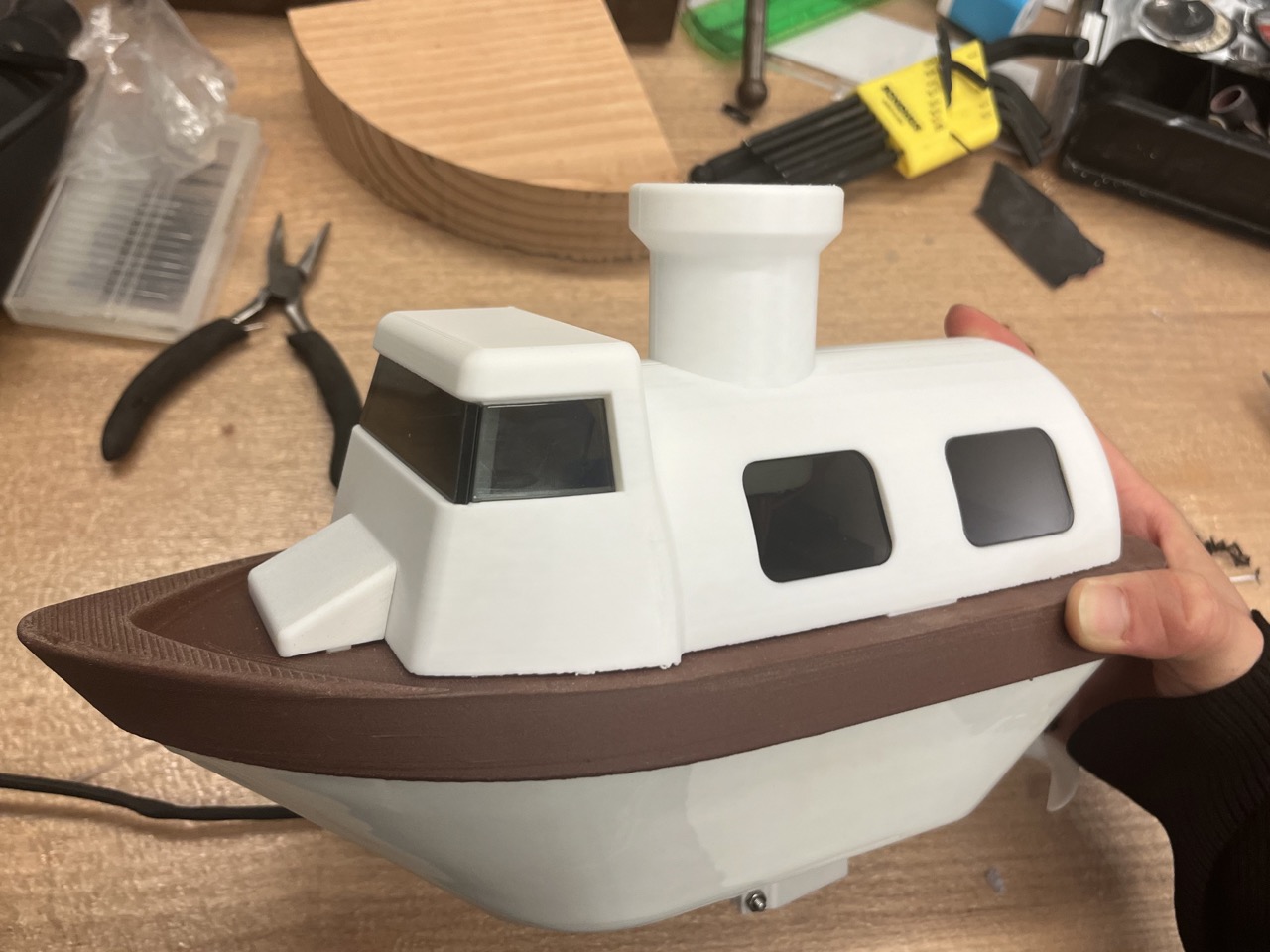
The boat assembly was shown below. The electronics could probably look better and operate more robustly if I designed more mounting for them, but I did not got enough time for that. Fortunately, the wiring this way worked.


Boat Wet Test and Final Appearance
The boat drowned for a few times during wet tests. A major reason was that the boat weight was unbalanced because of the placement of the battery to the right of the centerline. Also, the boat was tall and narrow, which made it easy to flip over. Moreover, water was leaking into the boat body from the rubber seal of the ball bearings, making the boat sink quickly. Fortunately most electronics survived after short submerges in water. One of the LEDs started to behave weird after getting in contact with water, and I had to discard it.
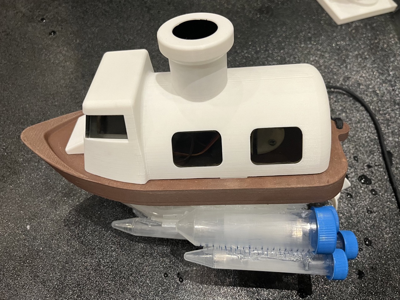
Eventually, I hot glued several Falcon tubes on the sides and at the bottom of the boat to make it float stably.
The video below shows the mist color change once the boat got in contact with water, and the boat moving forward on water!
Acknowledgements
Many thanks to Anthony for his invaluable advice and wholehearted support! I also wanted to thank Laxman for providing inspirations in my design, and JD for helping me tackle 3D printing issues.