This week we learned to make PCBs using a desktop milling machine and solder the components. After talking with Anthony, I realized that the routing on my previous week's PCB board layout could be improved. Specifically, the pins under the microcontroller did not need to be connected by traces on the PCB. Before soldering the microcontroller to the board, we can use an insulating tape to cover the pins under the microcontroller to prevent those pins from interfering with the other circuits on the board. This could save space on the board and reduce the number of rivets required on my board. Also, changing the orientation of some components on my board could make the routing easier. Those are important tips for me to learn to properly design a PCB, but since those problems did not violate circuit principles, I decided to make the board as it was first and see how it could go.
Materials/Components
- Microcontroller board: Seeed Studio XIAO RP2040
- Accelerometer: ADXL343BCCZ
Machines/Tools
- Othermill desktop milling machine
- 1/32'' flat end mill
- 1/64'' flat end mill
- Solder wire, solder paste, solder station, and hot air gun
Helpful Resources
Design Files
- PCB schematic & layout (same as last week): f3z download
Milling PCB Traces
I milled the traces with the Othermill machine using 1/64'' and 1/32'' flat end mills with the help of Anthony. Since my board was double-sided, a fixture was used to ensure proper alignment of the features on both sides. After installing the fixture, the machine probed the fixture's x, y positions with a broken mill that we installed upside down into the machine. After that, I stuck the FR1 board on the bed at the bottom left corner using a double-sided adhesive tape and milled the first layer without cutting the board outline, and then re-stuck the other side of the board to the bottom right corner to mill the other layer, including the outlines. The alignment was automatically calculated in the software, which was really cool.
The resulting board did not look very clean at first. There was debris of copper everywhere, and some traces were improperly connected together.
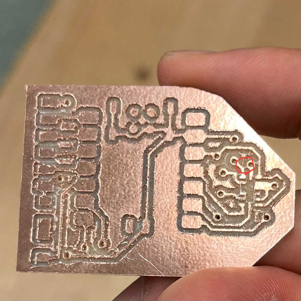
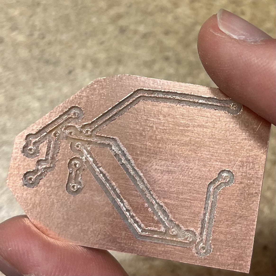
However, after some manual scraping and fixing, the resulting board looked ok:
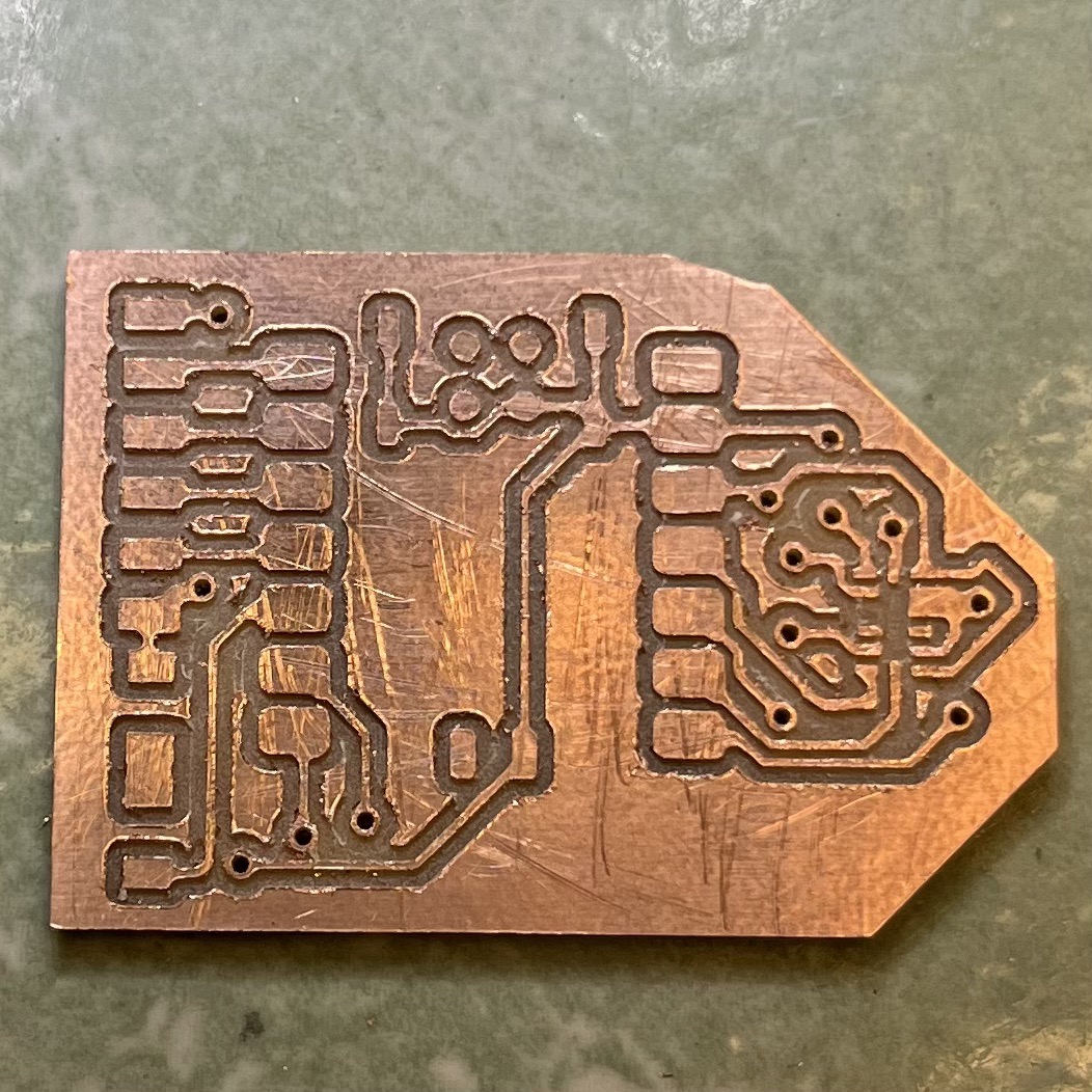
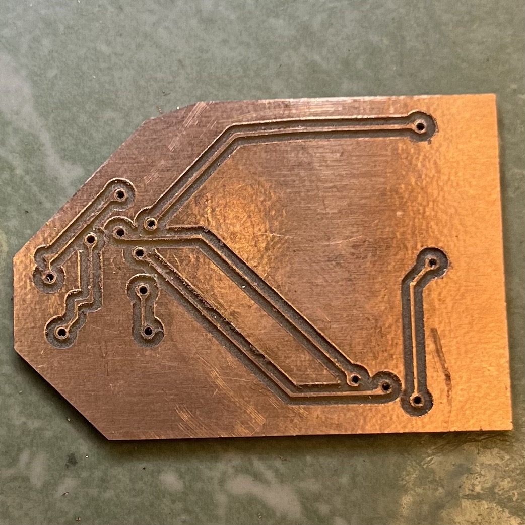
Something I learned: always make sure the mill was clean before start cutting. Double-sided adhesive is likely to stick around the mill after cutting the through-holes or board outlines. Also, don't stick the board too tight on the bed. Otherwise it will be difficult to get it off.
Soldering Components
Although I have soldered something before for hobby, after taking the class, I realized that I was not soldering properly. Both joints needed to be hot for the solder to attach to their surfaces, but my previous soldering probably resulted in a lot of cold joints, which explained why some LEDs were dim.
This time, I made sure to heat up the joints before feeding the soldering wire, and let the soldering iron to stay for a little while after feeding the wire to allow better adhering. I chose to use the lead-free solder, which was harder to use and required a higher temperature but safer. The through-holes were supposed to be fitted with rivets, but the 32-mil diameter through-holes did not seem to be big enough for the smallest rivets (0.6 mm ID), so I had to use wires instead. Luckily, the wires fitted with the holes, and the connections worked after I soldered both ends of the wires on the board.
The soldering process was tricky, and I found it hard to get to the result I imagined. Soldering the accelerometer was the hardest part, and Anthony showed me his method of soldering this component on my board because we didn't have a demonstration board, so I actually didn't solder this component, but it would be nice to try that by myself in the future (and our kind Anthony provided us with this opportunity in week 7!)
Here I wrote down how he did it this week:
- Put soldering paste on each pin on the board.
- Place the component on top and align it.
- Set the hot air gun to 330°C (can adjust between 270-330°C), and the air flow to ~1/3 of the maximum.
- Heat the component from the top while using the tweezer to apply a gentle pressure and hold the component in place.
- After the solder flows, stop the heating.
- Make sure not to overheat the component.
The soldered accelerometer looked like this:
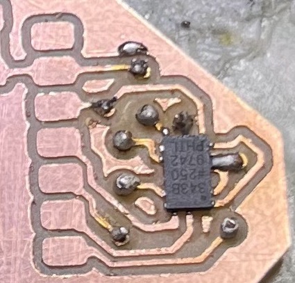
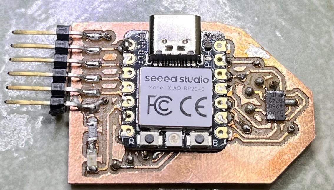
The next step was to solder the microcontroller. Initially I thought that we needed to put a little amount of solder on each pin on the board before putting on the microcontroller, but Anthony pointed out that this would result in unflatness under the microcontroller. A better way to do it was to put some solder on one pin on the board, align the microcontroller and use that joint to hold the microcontroller in place, solder the other pins, and resolder the initial pin to secure it. The final board was shown below:
Board Testing
I tested the communication between the microcontroller and the accelerometer using the Arduino IDE. First, I installed the board package for the Seeed XIAO RP2040 following the tutorial here. It was confusing at first because the port name was "UF2 Board" when I plugged in with the Bootloader button pressed, but changed to "/dev/cu.usbmodem1101" after the first program was loaded.
I installed the library for the accelerometer (Adafruit ADXL343) and used their example code "sensortest" to test the board with a few modifications.
The final test code is shown below:
            #include <Wire.h>
#include <Adafruit_Sensor.h>
#include <Adafruit_ADXL343.h>

#define ADXL343_SCK 2
#define ADXL343_MISO 4
#define ADXL343_MOSI 3
#define ADXL343_CS 1

/* Assign a unique ID to this sensor at the same time */
/* Uncomment following line for default Wire bus      */
// Adafruit_ADXL343 accel = Adafruit_ADXL343(12345);

/* NeoTrellis M4, etc.                    */
/* Uncomment following line for Wire1 bus */
//Adafruit_ADXL343 accel = Adafruit_ADXL343(12345, &Wire1);

/* Uncomment for software SPI */
//Adafruit_ADXL343 accel = Adafruit_ADXL343(ADXL343_SCK, ADXL343_MISO, ADXL343_MOSI, ADXL343_CS, 12345);

/* Uncomment for hardware SPI */
Adafruit_ADXL343 accel = Adafruit_ADXL343(ADXL343_CS, &SPI, 12345);

void displayDataRate(void)
{
    Serial.print  ("Data Rate:    ");

    switch(accel.getDataRate())
    {
    case ADXL343_DATARATE_3200_HZ:
        Serial.print  ("3200 ");
        break;
    case ADXL343_DATARATE_1600_HZ:
        Serial.print  ("1600 ");
        break;
    case ADXL343_DATARATE_800_HZ:
        Serial.print  ("800 ");
        break;
    case ADXL343_DATARATE_400_HZ:
        Serial.print  ("400 ");
        break;
    case ADXL343_DATARATE_200_HZ:
        Serial.print  ("200 ");
        break;
    case ADXL343_DATARATE_100_HZ:
        Serial.print  ("100 ");
        break;
    case ADXL343_DATARATE_50_HZ:
        Serial.print  ("50 ");
        break;
    case ADXL343_DATARATE_25_HZ:
        Serial.print  ("25 ");
        break;
    case ADXL343_DATARATE_12_5_HZ:
        Serial.print  ("12.5 ");
        break;
    case ADXL343_DATARATE_6_25HZ:
        Serial.print  ("6.25 ");
        break;
    case ADXL343_DATARATE_3_13_HZ:
        Serial.print  ("3.13 ");
        break;
    case ADXL343_DATARATE_1_56_HZ:
        Serial.print  ("1.56 ");
        break;
    case ADXL343_DATARATE_0_78_HZ:
        Serial.print  ("0.78 ");
        break;
    case ADXL343_DATARATE_0_39_HZ:
        Serial.print  ("0.39 ");
        break;
    case ADXL343_DATARATE_0_20_HZ:
        Serial.print  ("0.20 ");
        break;
    case ADXL343_DATARATE_0_10_HZ:
        Serial.print  ("0.10 ");
        break;
    default:
        Serial.print  ("???? ");
        break;
    }
    Serial.println(" Hz");
}

void displayRange(void)
{
    Serial.print  ("Range:         +/- ");

    switch(accel.getRange())
    {
    case ADXL343_RANGE_16_G:
        Serial.print  ("16 ");
        break;
    case ADXL343_RANGE_8_G:
        Serial.print  ("8 ");
        break;
    case ADXL343_RANGE_4_G:
        Serial.print  ("4 ");
        break;
    case ADXL343_RANGE_2_G:
        Serial.print  ("2 ");
        break;
    default:
        Serial.print  ("?? ");
        break;
    }
    Serial.println(" g");
}

void setup(void)
{
    Serial.begin(115200);
    while (!Serial);
    delay(5000);
    Serial.println("Accelerometer Test"); Serial.println("");

    /* Initialise the sensor */
    if(!accel.begin())
    {
    /* There was a problem detecting the ADXL343 ... check your connections */
    Serial.println("Ooops, no ADXL343 detected ... Check your wiring!");
    while(1);
    }

    /* Set the range to whatever is appropriate for your project */
    accel.setRange(ADXL343_RANGE_16_G);
    // accel.setRange(ADXL343_RANGE_8_G);
    // accel.setRange(ADXL343_RANGE_4_G);
    // accel.setRange(ADXL343_RANGE_2_G);

    /* Display some basic information on this sensor */
    accel.printSensorDetails();
    displayDataRate();
    displayRange();
    Serial.println("");
}

void loop(void)
{
    /* Get a new sensor event */

    // Serial.println("testloop");
    sensors_event_t event;
    accel.getEvent(&event);

    /* Display the results (acceleration is measured in m/s^2) */
    // Serial.print("X: "); Serial.print(event.acceleration.x); Serial.print("  ");
    // Serial.print("Y: "); Serial.print(event.acceleration.y); Serial.print("  ");
    // Serial.print("Z: "); Serial.print(event.acceleration.z); Serial.print("  ");Serial.println("m/s^2 ");

    Serial.print(event.acceleration.x);
    Serial.print(",");
    Serial.print(event.acceleration.y);
    Serial.print(",");
    Serial.println(event.acceleration.z);
    delay(500);
}
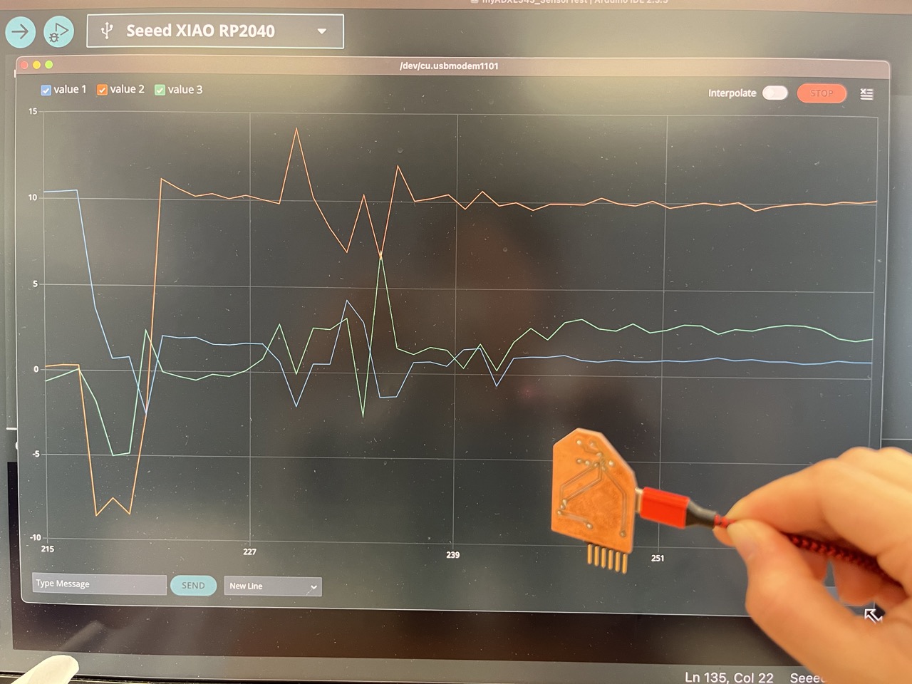
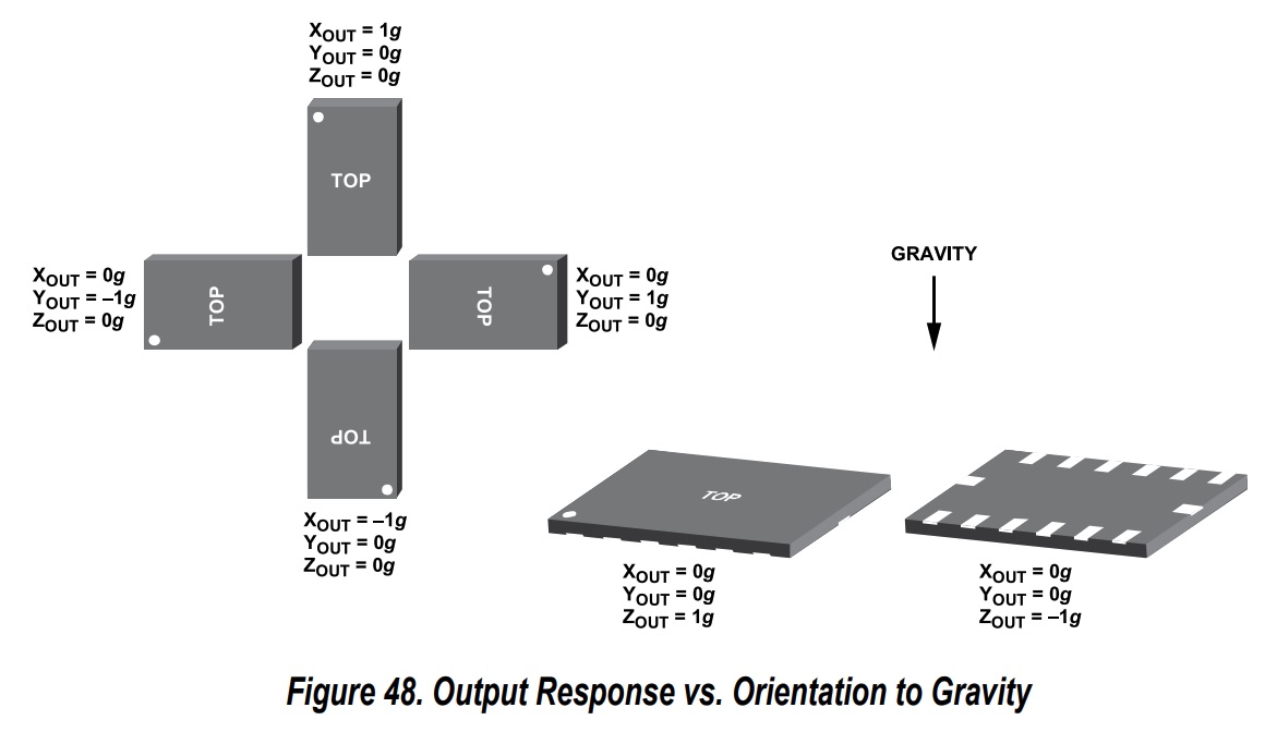
As can be seen in the images below, the detected accelerometer varied with the orientation of the chip, showing gravity's effect on different axes.
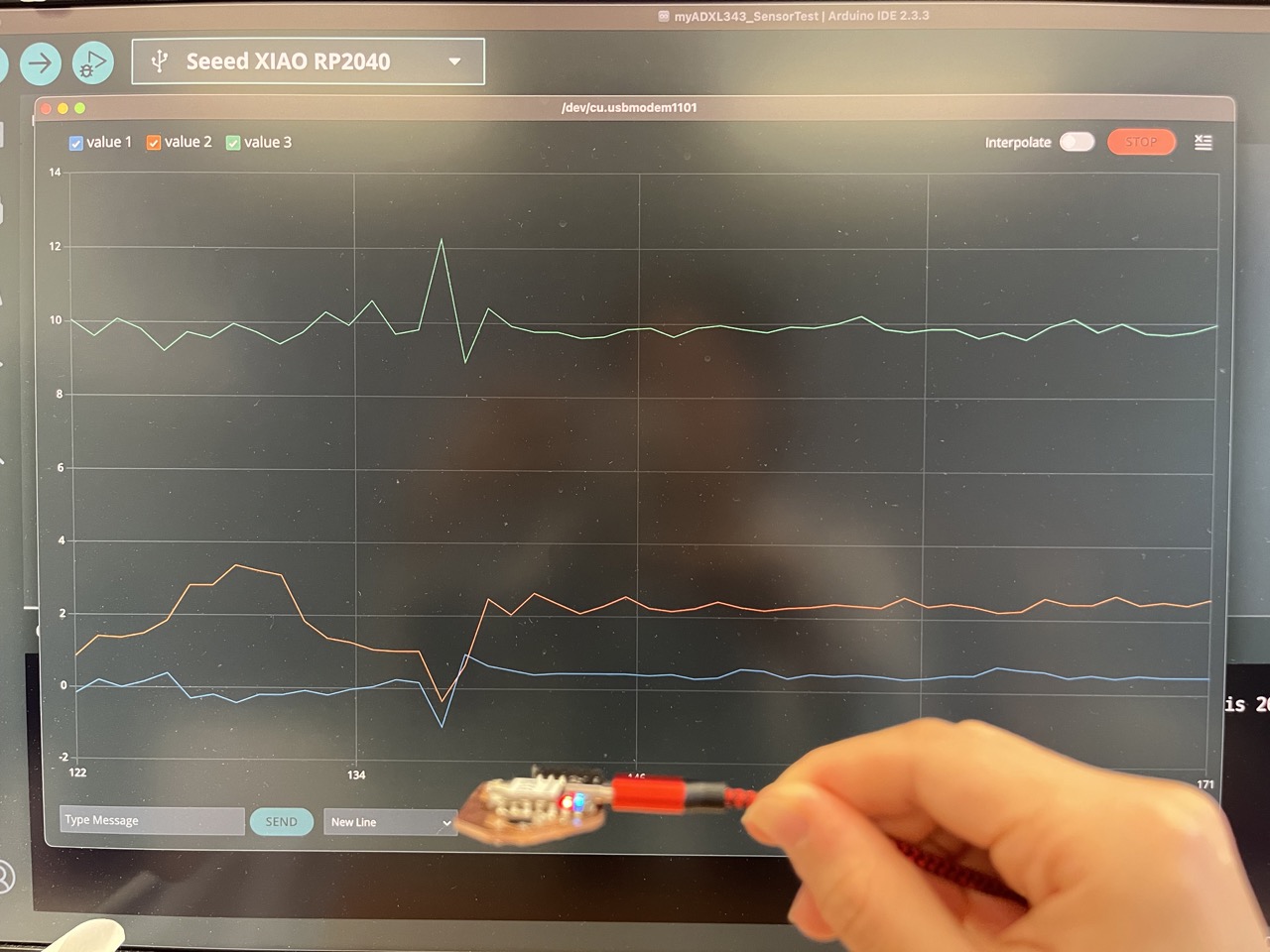
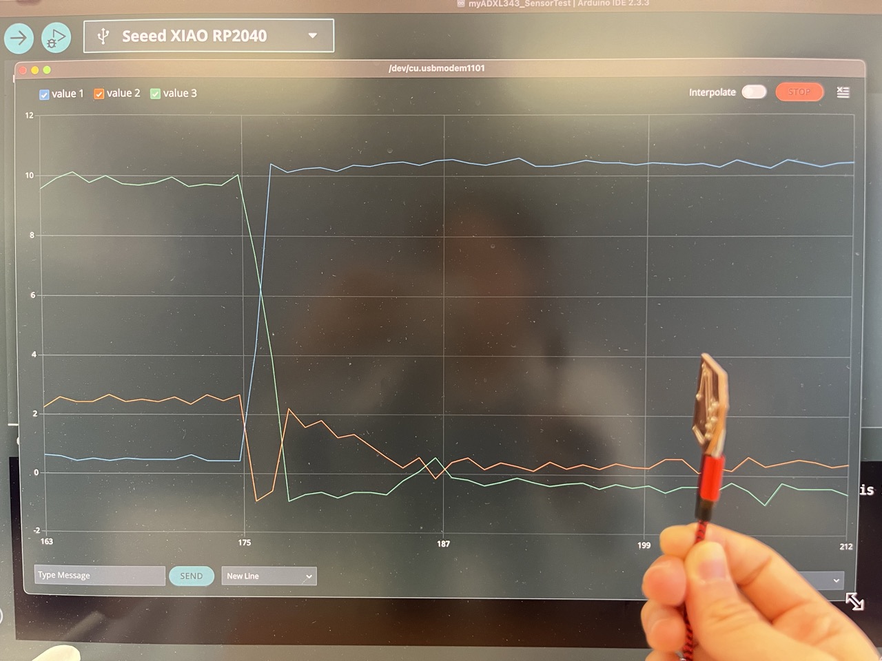
This is in accordance with the sensor's response vs. orientation to gravity as shown in the datasheet:
Acknowledgements
I had no experience with PCB production before and little experience with soldering, and most people in our section were in a similar situation, but Anthony was patient and kind enough to guide us through all those processes and answer our tons of questions even though his schedule was getting crazy. I really appreciate his kindness and dedication and want to express my greatest gratitude here!