This week I would like to design a PCB that allows interaction between an IMU and a microcontroller. The idea is to put the board inside a wand, and use the motion signals coming from the IMU to control some other devices such as LEDs. Imaging casting a spell with a wand to turn on or off your room light!
Materials/Components
- Microcontroller board: Seeed Studio XIAO ESP32C3
- IMU: BNO085 Adafruit 9-DOF Orientation IMU Fusion Breakout
- 3.7 V lithium battery (to be added)
- FR1 single-sided copper board
Selection criteria: The XIAO ESP32C3 has both bluetooth and WIFI capabilities, which is very helpful because I want the wand to be completely wireless. Previously, I explored the capabilities of an accelerometer (ADXL343BCCZ-RL7) in week 5, but I felt it would be better for the wand to have a full IMU that integrates data from an accelerometer, a gyroscope, and a magnetometer, so BNO085 was chosen. Both of the components are small and suitable to be put inside a wand.
Machines/Tools
- Othermill desktop milling machine
- 1/32'' flat end mill
- 1/64'' flat end mill
- Solder wire, solder paste, solder station, and hot air gun
Software Platforms
- PCB schematic & layout: Autodesk Fusion 360 (EAGLE)
- Microcontroller coding: Arduino IDE 2.3.3
Helpful Resources
- XIAO-ESP32C3 Getting Started Guide
- BNO085 Chip Datasheet
- BNO085 Breakout Board Documentation
- Adafruit BNO08x Arduino Library
Design Files
- Schematic and PCB layout: f3z download
PCB Schematic and Layout
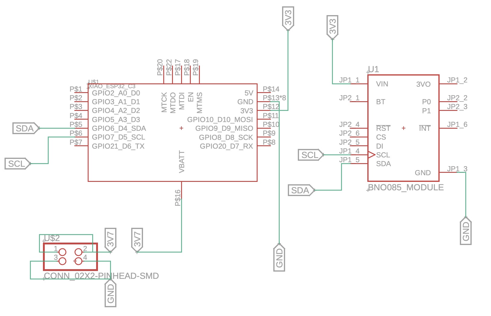
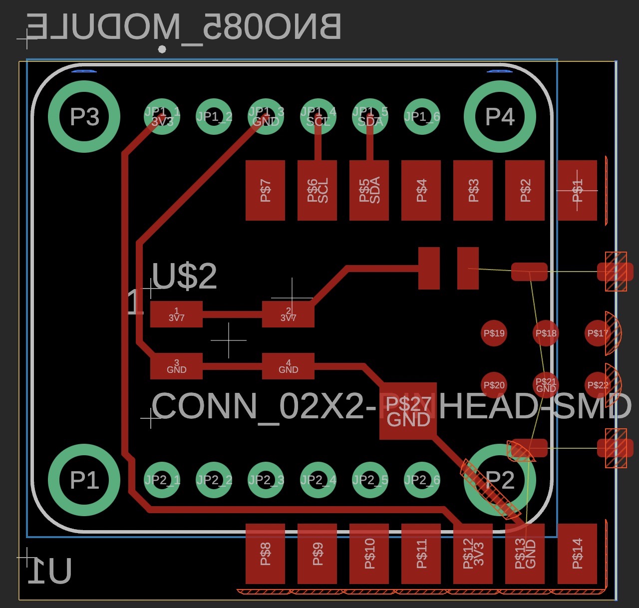
Since I wanted the board to be as small as I could make it, I placed the components back-to-back on the opposite layers of the PCB as shown below (note that the BNO085 component was mirrored).
Design Considerations
The back-to-back configuration added difficulty to the layout design, and several considerations came up, but with the help of Anthony, we figured them out:
-
As BNO085 is a through-hole component instead of a surface-mounted component in the library,
we needed to make sure that the soldered through-hole pins wouldn't end up under the microcontroller
board,
or otherwise the microcontroller board wouldn't have a flat surface to sit on.
Luckily, if we use I2C connections,
only four pins needed to be connected on the IMU board,
and the four pins are all on the same side of the board.
Therefore, we could expose the used pins on the side of the microcontroller
while leaving all the unused pins underneath.
Interestingly, from the BNO085 breakout board documentation, The I2C connection may not work with ESP32:However, since it doesn't explicitly say ESP32-C3, we decided to give it a try.
-
Since I wanted the final board to work completely wirelessly,
I needed to connect a battery to power the microcontroller.
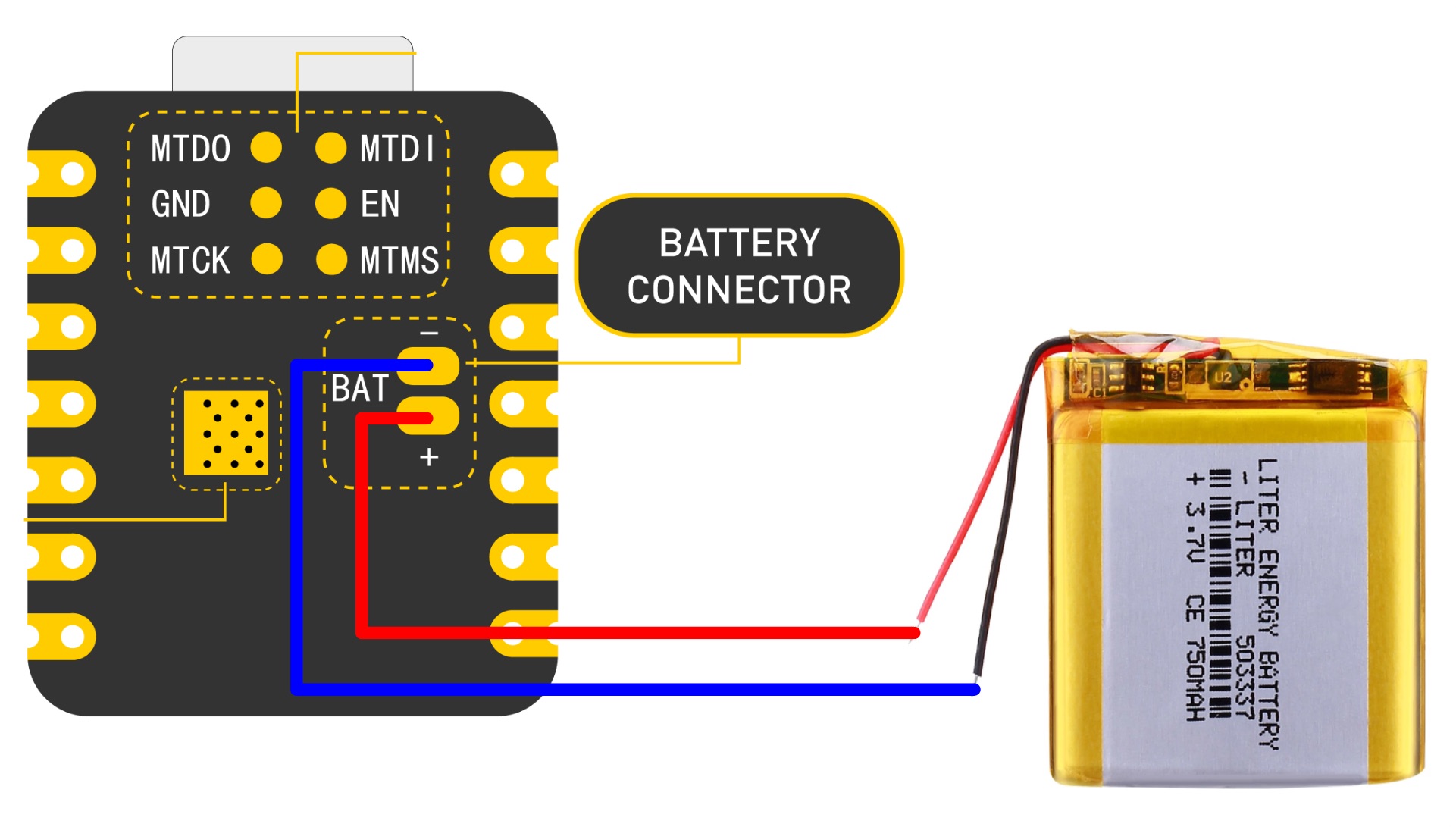
The battery pin of XIAO ESP32-C3 is on the back of the board:
If I did't have this back-to-back configuration, I could probably just drill a through-hole at this location on the board and connect the battery from the back. However, as the IMU board is on the other side, I needed to find another method.
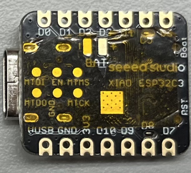
Initially, I was trying to avoid soldering this battery pin to the board directly, because it would be hard to get a good connection as we couldn't see anything underneath the microcontroller. Therefore, I was thinking about soldering the BAT+ pin and the nearest I/O pin (D3 pin) directly on the back of the microcontroller, and then power D3 instead of powering the BAT+ pin directly. However, Anthony pointed out that the solder would create an uneven surface, and more importantly, if there were a mistake in my code (e.g. accidentally setting the D3 pin low), the microcontroller board could be burnt and would never function again. That was a valuable advice I got, so I decided to go with soldering the BAT+ pin on the board.
I wanted to wire the battery pins to a position on board for easy access, so ideally I would choose a 2-pin surface-mounted connector on the design for this purpose, but I didn't find one in the library, so I just used a 4-pin connector in the design with two pins underneath the microcontroller. - Initially, I was only using the ground pin under the microcontroller to wire ground to the IMU and the battery because the ground pin on the side of the microcontroller was at a position difficult to route. However, Anthony pointed out that I could just place the trace over the through-hole since we were not using the through-hole, so the board ended up as shown in the image above.
PCB Milling
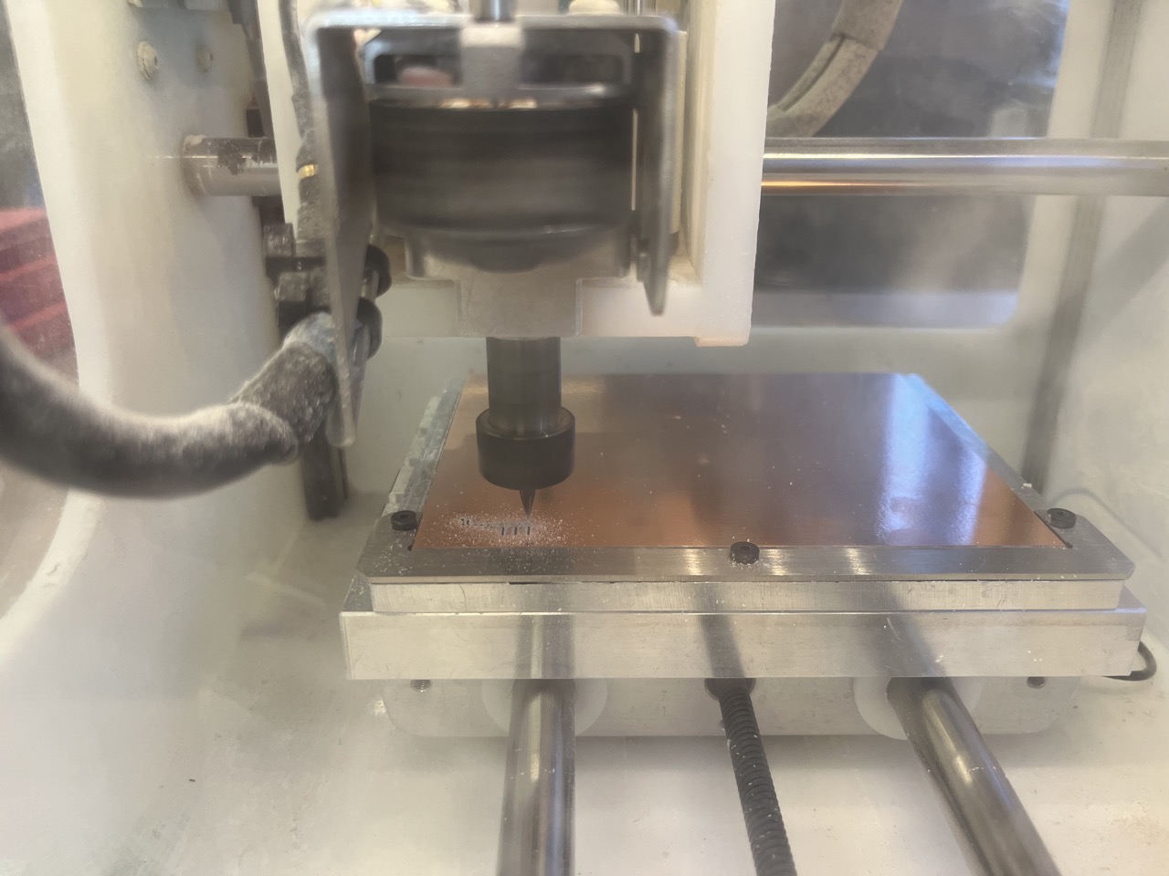
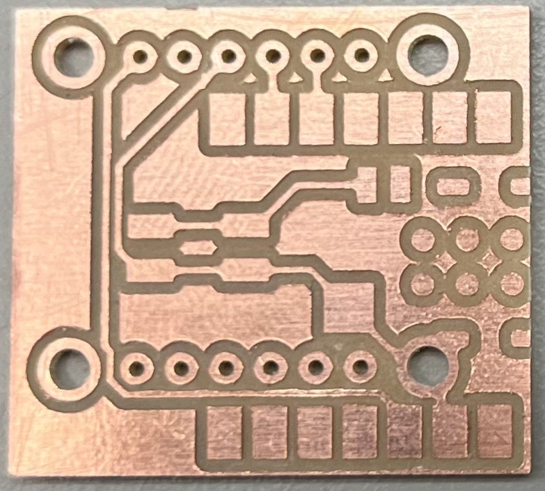
With the experience from last time, the milling went smoothly, and the board came out well:
Component Soldering
Now comes the most challenging part of this work -- solder the BAT+ pin on the microcontroller to the board!
I first used an insulating tape to tape all the pins except the BAT+ pins under the microcontroller:
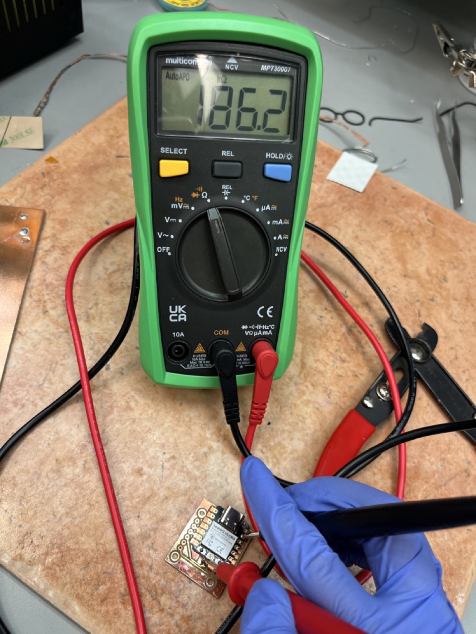
After that, Anthony showed me how to probe the battery pin with the ground and usb pin using a multimeter with the resistor/diode mode. This was a really helpful advise which I admired. Although the values from the multimeter were "garbage", having a value (~180 k ohm in this case) indicated some electrical connections within the board, and we could use that to test whether the battery joint was soldered properly afterwards.
After dispensing some solder paste on the BAT+ pin on the board (and a little on the microcontroller back too), I placed the board on the hot plate under the hot air gun and aligned the microcontroller board. I set the hot plate to ~290°C and the hot air gun to 330°C and started warming the board from both the bottom and the top. Although the FR1 board has a bad thermal conductivity, having some temperature on the back could help, as suggested by Anthony.
I was moving the hot air gun around the microcontroller region at a distance, but Yuval said that I could get closer and have the air stream more focused on the pin area. After a while, we felt that the time could be enough, so I removed the heat, let it cool for a while, and then checked the connections.
The microcontroller didn't move relative to the board after I tried to slide it with tweezers, so I thought the connections should be good. However, with the multimeter, I couldn't get a resistance value from the BAT+ pad to the other pins, so I did the soldering process again.
I realized that copper conducts heat well, so I could heat the pad exposed on the board that was electrically connected to the pad under the BAT+ pin, and the heat should get to that pad through the copper trace. Therefore, I also heated that area, in addition to the microcontroller on the top. This time, after a while, when I almost burned my board, I saw the clear fluid from the solder paste coming out from under the microcontroller, and that was when I knew that the solder paste became a solder joint. However, I didn't wait enough time for the board to cool down, and the two parts fell apart when I used tweezers to probe them. That was disappointing, but I saw the shiny solder balls on both the microcontroller back and the PDB board.
The third time, I finally got it to work! Probing with the multimeter showed good electrical connections:
After soldering the other joints, the resulting board looked like this:
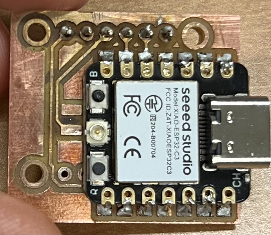
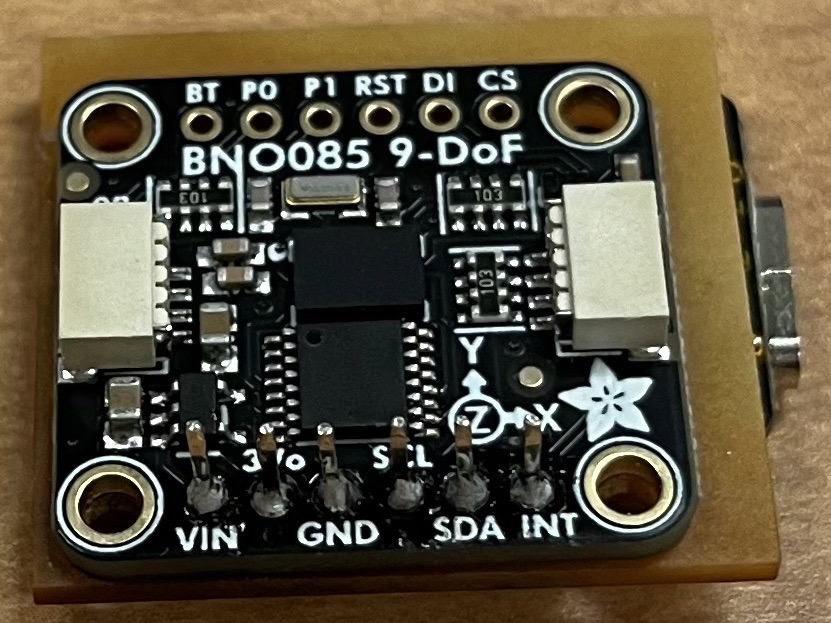
The plastic holders on the through-hole pins were removed so that the IMU can directly sit flat on the back of the PCB board.
Board Testing
Using the examples from the Adafruit BNO08x Arduino Library, I successfully got the data from the IMU. It turned out that the I2C connection worked between the two components (although sometimes after uploading new codes, the IMU couldn't be detected, and I would have to press the reset button on the microcontroller to restart the connection, which I don't know why). The four videos below showed the data of linear acceleration (without gravity), gyroscope angle measurement, magnetometer measurement, and the interpreted rotation, respectively.
Acknowledgements
I would like to thank Anthony for his help and the valuable advices he gave as always.
He also held a soldering practice session where we soldered resistors,
connectors, and the tricky accelerometer part, which I learned a lot from.
Here is an image of the practice board I made during the soldering practice session:
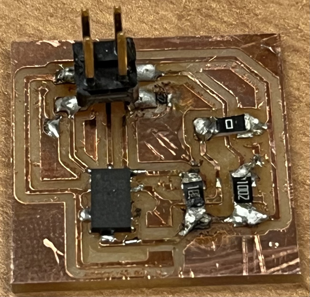
It still looked ugly, but I learned that the soldering temperature is critical to the success of a joint.
I would also like to thank Yuval, who helped me with the tricky soldering, and offered me valuable suggestions!
