This week, I started to work on my final project, so I created a board that allows connections of a microcontroller with a DC motor, a servo, a NeoPixel LED (strip), a mist generation module, and a TDS sensor.
Materials/Components
- Microcontroller board: Seeed Studio XIAO ESP32C3
- Servo: MG90S
- 3-6V DC motor: 130 DC motor
- NeoPixel LEDs (to be added): WS2812B
- TDS Sensor (to be added): SEN0244
- Mist Generator/Ultrasonic Water Atomizer (to be added): SJ62X4-No Switch
- 5 V battery: Miady 5V/2.4A small portable charger
- FR1 single-sided copper board
Selection criteria: The XIAO ESP32C3 microcontroller board was chosen for its compactness and bluetooth and wifi capabilities. The 3-6V small DC motor was chosen because I didn't need the boat to run super fast, but a future improvement will be to use a more powerful motor to control the propeller or use a waterjet.
Machines/Tools
- Othermill desktop milling machine
- 1/32'' flat end mill
- 1/64'' flat end mill
- Solder wire and solder station
Software Platforms
- PCB schematic & layout: Autodesk Fusion 360 (EAGLE)
- Microcontroller coding: Arduino IDE 2.3.3
Helpful Resources
- XIAO-ESP32C3 getting started guide
- MG90S servo datasheet
- NeoPixel LED datasheet
- TDS sensor datasheet
- ESP32Servo Arduino library
- DC motor basic hookup guide
Design Files
- Schematic & PCB layout: f3z download
PCB Schematic and Layout
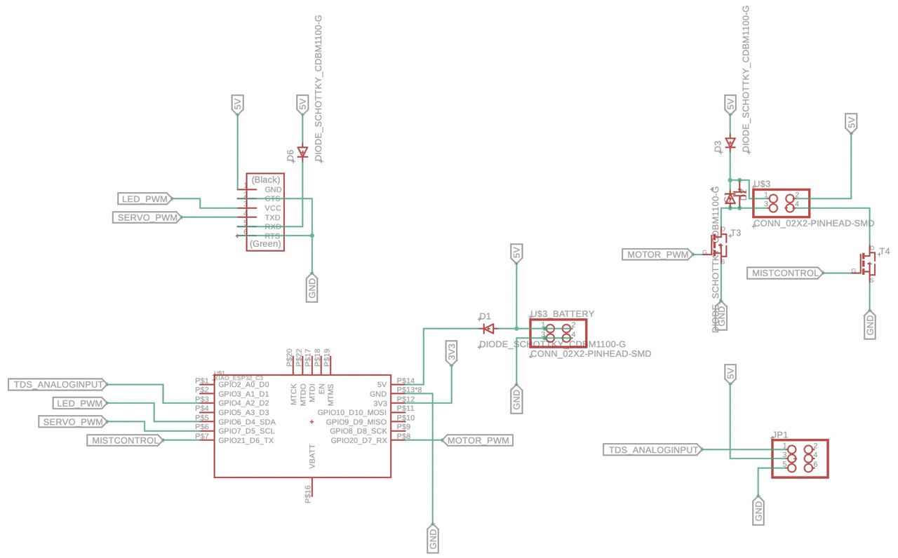
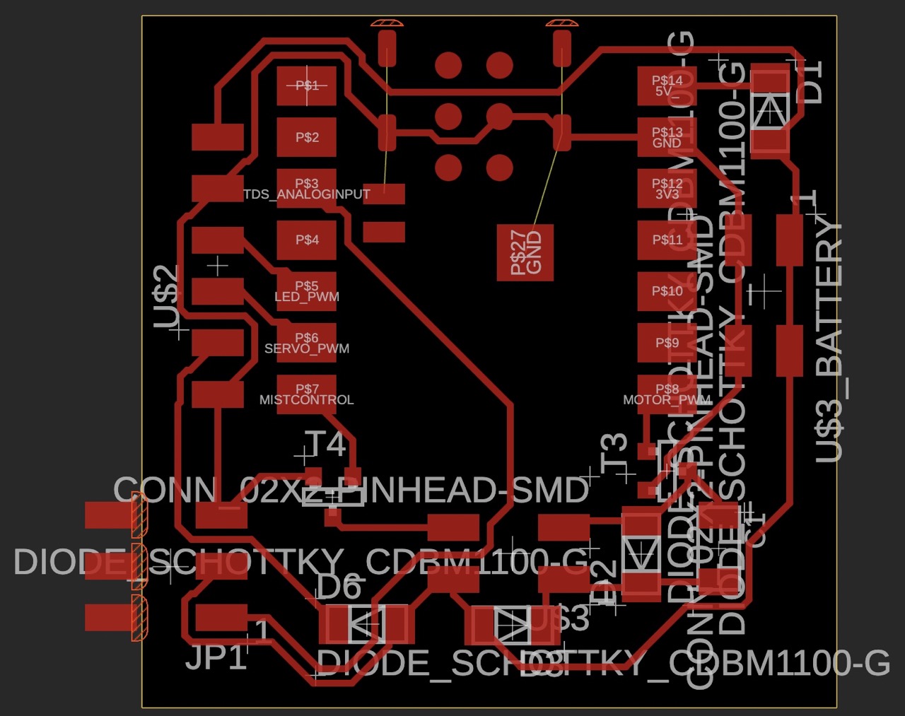
Note that in the layout, the three pins out of the board outline were unused.
The pin functions and hookup explanations for each of the components are specified below:
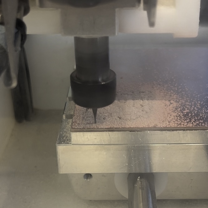
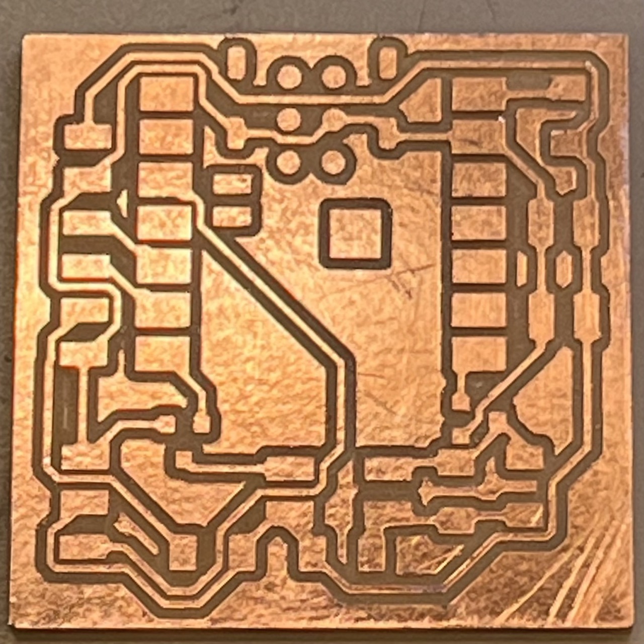
PCB Milling
The milling went well as before:
Component Soldering
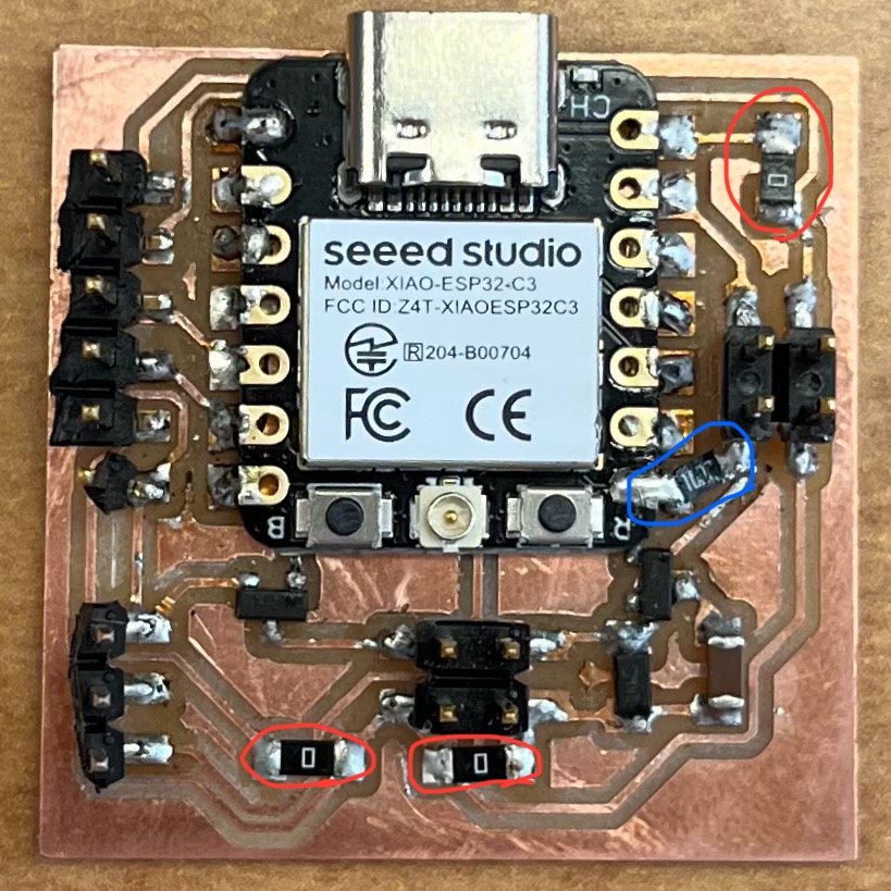
The microcontroller back was covered with insulating tape before soldering, and the soldered board is shown below:
Board Testing
Servo Test Code
The code was modified from the ESP32Servo Arduino Library. Although 0 and 180 degrees corresponded to 1000us and 2000us on the servo datasheet, 180 degrees could not be reached using those two values, so 500us and 2500us were used instead.
            /* Sweep
by BARRAGAN <http://barraganstudio.com>
This example code is in the public domain.

modified 8 Nov 2013
by Scott Fitzgerald

modified for the ESP32 on March 2017
by John Bennett

modified by Fan Xue on Nov 2024

see http://www.arduino.cc/en/Tutorial/Sweep
for a description of the original code
*/


#include <ESP32Servo.h>

Servo myservo;  // create servo object to control a servo

int pos = 0;    // variable to store the servo position

#if defined(CONFIG_IDF_TARGET_ESP32S2) || defined(CONFIG_IDF_TARGET_ESP32S3)
int servoPin = 17;
#elif defined(CONFIG_IDF_TARGET_ESP32C3)
int servoPin = 7;  // Used
#else
int servoPin = 18;
#endif
// int servoPin = 4;

void setup() {
    // Allow allocation of all timers
    ESP32PWM::allocateTimer(0);
    ESP32PWM::allocateTimer(1);
    ESP32PWM::allocateTimer(2);
    ESP32PWM::allocateTimer(3);
    myservo.setPeriodHertz(50);    // standard 50 hz servo
    myservo.attach(servoPin, 500, 2500); //
    // using default min/max of 500us and 2500us
    // different servos may require different min/max settings
    // for an accurate 0 to 180 sweep
}

void loop() {

    for (pos = 0; pos <= 180; pos += 1) { // goes from 0 degrees to 180 degrees
        // in steps of 1 degree
        myservo.write(pos);    // tell servo to go to position in variable 'pos'
        delay(15);             // waits 15ms for the servo to reach the position
    }
    for (pos = 180; pos >= 0; pos -= 1) { // goes from 180 degrees to 0 degrees
        myservo.write(pos);    // tell servo to go to position in variable 'pos'
        delay(15);             // waits 15ms for the servo to reach the position
    }
}
Motor Test Code
        const int motorPin = 20;

void setup() {
    pinMode(motorPin, OUTPUT);
}

void loop() {
    //Motor
    int speed;
    for (speed = 0; speed <=255; speed +=50){
    analogWrite(motorPin, speed);
    delay(1000);
    }
    analogWrite(motorPin, 0);
    delay(1000);
}
Demo
Interestingly, the servo and motor were not working when connected to my laptop direclty. Only a small range of angle/speed could be reached, and afterwards they got disconnected to my laptop, reconnected to my laptop and reset. Anthony said it was probably because my computer could not provide enough current for those parts, and whenever the current exceeded the threshold, the USB got disconnected. Therefore, I tried to power by battery instead of by my laptop, and it worked afterwards. Below is a comparison between powering the servo by laptop and by battery.
Acknowledgements
I would like to thank Anthony for providing me with valuable advices on many aspects and helping me with component testing, Samual for helping me with schematics design and component testing, and Yuval for idea brainstorming and component testing.