Week 8: Input Devices
For this part of the project, a simple switch was sufficient to meet the requirements. The switch is used to detect whether the boogie board is in use or available. It also serves as a diagnostic tool to alert me if something malfunctions.
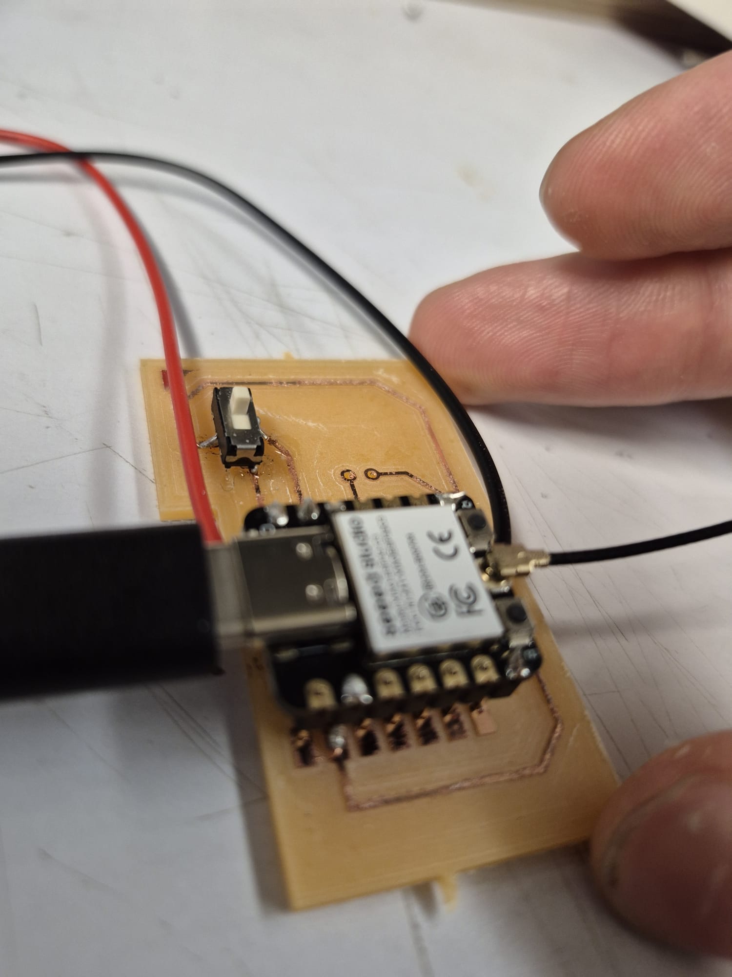
After following the instructions provided by Seeed Studio on programming the microcontroller using the Arduino interface, I implemented the following code to operate the switch:
// Define the pin to which the switch is connected
const int switchPin = D1;

void setup() {
  // Start the Serial Monitor (set your desired baud rate)
  Serial.begin(115200);

  // Configure the switch pin as an input with the internal pull-up resistor
  pinMode(switchPin, INPUT_PULLUP);
}

void loop() {
  // Read the state of the switch:
  //  - LOW means the switch is pressed (ON)
  //  - HIGH means the switch is not pressed (OFF)
  int switchState = digitalRead(switchPin);

  if (switchState == LOW) {
    Serial.println("Switch is ON");
  } else {
    Serial.println("Switch is OFF");
  }

  // Add a small delay to avoid flooding the Serial Monitor
  delay(500);
}

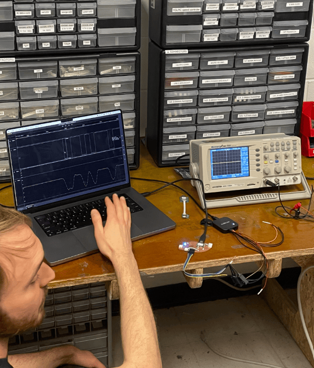
The terminal output successfully displays the switching states, confirming that the switch is functioning as intended.