01: The Laser Cardboard Alphabet
For this assignment I decided to make a construction kit that can make letters of the alphabet (capital letters).
First, I needed to split the letters into components. This was easy for the ones that don’t have diagonal lines, as there’s a lot of component reuse.
Diagonal Attempt
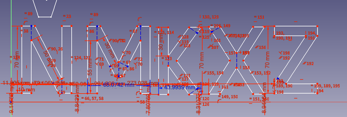
Some of the letters (A, K, M, N, R, S, V, W, X, Y, Z) can use diagonal lines to look nicer. However, there are many slopes of diagonals and many different types of intersections with them, so adding diagonals creates a lot of components used by only one letter. I tried to CAD the letters to figure out all the parts, minimizing the number of components needed, but for a reason that will be explained later, I didn’t have time to finish. So, no diagonals.
Component Makeup
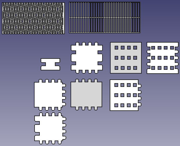
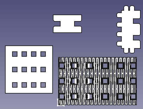
Each component consists of two top pieces (one of which goes on the bottom), a middle piece (which contains the slot joints), and some side pieces. They are arranged so that the side sticks out from the top and bottom. The ones for a straight are shown below.
The 1st CAD
So, component making time. My plan was to use finger joints to make the various component, then use slot joints to assemble the component together. I settled for a component side length of 40 mm after finding 30 mm to be too small, and 4 finger of width 4 mm with an 8 mm offset between consecutive fingers.
Now, it turns out that the end, straight, corner, 3-way, and 4-way are made up of a bunch of square-shaped pieces with various shapes cut out of them. Perfect for parametric modelling. But the first CAD had a bunch of copypasting (the finger joints etc. were made parametric with a spreadsheet, however.)
You may notice that the above figure also has some flexy-flexy parts. These are the sides of the bend. The one with rectangle holes was made first, since it was easier to CAD. However, it turned out to be perfectly rigid, probably because even 3 horizontal lines is too many, even when the width is 1 mm. So I had to use diamonds, which flexed much better. Originally it was too flexy so I fattened the net.
Anyway, all the copypasting made me want to try again with more referencing.
The 2nd CAD: Now with Linked Copies
This was pretty much the same as the first, but with more PartDesign usage and more referencing instead of copypasting. This makes changing designs easier, but I later realized that if I wanted to easily make the very similar pieces of the components, I needed a way to create a linked copy that has its own parameters.
The 3rd CAD: Parts are Functions?!
With this, I attempted to somehow model a part so it can effectively be a “function” that takes some parameters and outputs a piece. Then if I change the “function”, all the pieces that use it will update. For this, I found out about configuration tables, which was nice. And it worked, until I needed multiple “function”s. Apparently if a “function” doesn’t use all the configuration tables you define, and you try to instantiate it and change a parameter, FreeCAD complains. Great.
The 4th CAD: We Render CAD in Blender
So, I used a software that I was very used to: Blender, and specifically, it’s amazing Geometry Nodes feature. Geometry Nodes (and node groups) are effectively functions that take parameters and output a geometry (and/or other parameters). Perfect! There are some weaknesses, though: Blender can’t do Booleans on curves (so they have to be approximated), and making an expression using nodes is more tedious than just writing an expression. But it still was nice.
(I did cheat on the hinge pieces and the diamonds (but not the piece that cuts the diamonds out) and modelled them directly without using parameters. But by this time I already knew what parameters I wanted, so it’s fine.)

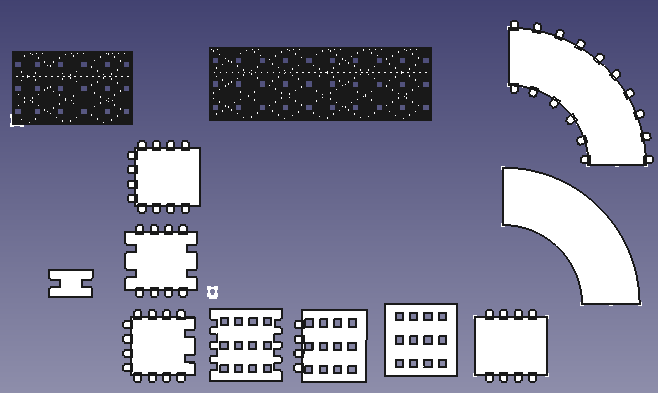
All the pieces
Here are all the pieces used in the components:
Yes, there’s a stand, which comes with an end component and a middle component. Hooked-h-shaped pieces are used to stand letters on the stand.
Results
Here is an example of what can be built with this kit:

This took 51 straight components, 19 end components, 0 corner components, 9 3-way components, 0 4-way components, 10 bend components, and 0 B-bend components to make, along with 2 stand ends and 19 stand middles. In total, several hours of laser cutting. I also got lucky with this example in that there were no horrible letters to stand, like F’s or P’s.
Vinyl Cutting
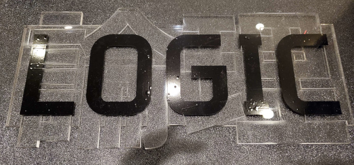
For a piece to go with my final project, I vinyl cut the word LOGIC in bold black letters.

It was imported into mods. I set the origin of the cutter to a nice position, locked in the vinyl, and sent the job to the cutter.
I cut out a rectangle containing the cut pattern, put it on what Anthony calls “transfer tape” (front side touching the tape), carefully remove the outer perimeter from the tape, and put the tape and the letters on some suspicious acrylic that I laser cut. Then I carefully took out just the tape, leaving the letters behind. The result:
