04: Electronics Design
For this week, I decided to design a board that could be used in my final project, the sprinkler printing machine. I decided to use KiCad. I haven’t done much with electronics in the past, so I had to learn from the beginning.
After following the tutorial, I needed to figure out what microcontroller I was going to be using in the first place (I would like it to support 3 servos (after that plane movement 3D print I realized that one of the axis wants 2 motors at different places), a USB port (for loading in shape files), and a display and some buttons).
I looked at the datasheet for the ATSAMD21/ATSAMDA1 family of microcontrollers but it was very overwhelming, so first I decided to pick out servos and stuff to see what features I even need. Servos were easy. As for the display, I decided to use the EA eDIP240-7 display, which is a 240×128 black & white display. (don’t need color here). For the USB port, I used a USB 2.0-only USB-C port, because I don’t think I need USB 3.0 for this and I don’t want to overcomplicate things when they’re already complicated.
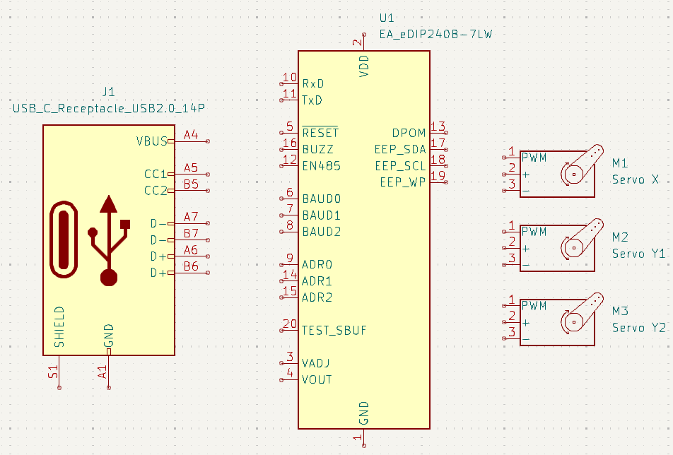
Now to understand all the datasheets and pick a microcontroller. At this point, I wanted to make sure everything had a footprint, and I downloaded and installed the fab library. I wanted to go with the ATSAMD21E17A-AUT but it operates on 3.3V only while the display operates on 5V only. I don’t want to deal with the incompatibility when connecting pins between them, so time to use the ATtiny3216-SFR microcontroller. I’m worried about the fact that there’s only one SPI interface… Well, actually, I’ll use this OLED display instead, which can operate at 3.3V for logic (though its display is 128×64. Shame.). The display itself runs on 12V, however, so I’ll need to figure that out.
Well, after some indecisiveness, I decided to go back to the ATSAMD21E17A-AUT and use a regulator, since I planned to be doing some servo math and wanted a 32-bit processor for it.
First, I tried to wire up the power for the microcontroller. Looking at the datasheet §44, the recommended power supply connections are full of decoupling capacitors and even an inductor, and being mostly a beginner to real-world electronics, I got overwhelmed. But I decided to just try wiring up the power supply and reset pin anyway. I also included a USB 2.0-only USB C receptacle, intended for feeding the microcontroller shape files to draw with the servos, similarly to electronics simulation week.
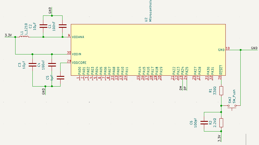
I asked for feedback and was told that the USB C receptacle is unmillable and to use a USB A receptacle instead. Much simpler. I was also shown an example wiring for the ATSAMD21E. Regarding the display, I was told to just use a simple I²C header instead of that complicated display that needs its screen powered by 12V. Oh, and I needed a JTAG header for bootloading.
(By the way, the display datasheet linked eariler is pathetic and missing lots of information like what the commands even are). A much better datasheet is the SSD1306 datasheet, which covers this display too.
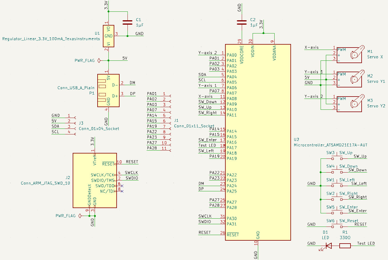
So I started from the example this time and added components (servos, buttons, I²C header), paying attention to the datasheet (especially §7.1, which lists multiplexing possibilities) to make sure that things like servo PWM are going to the right pins. An electronics rule check revealed that 5V, GND, and RESET weren’t being driven by outputs, so I added a PWR_FLAG to indicate that 5V and GND are indeed powered and added a RESET button. Finally, I added an 11-socket header to make use of the 11 leftover pins on the microcontroller.
The final schematic is shown below:
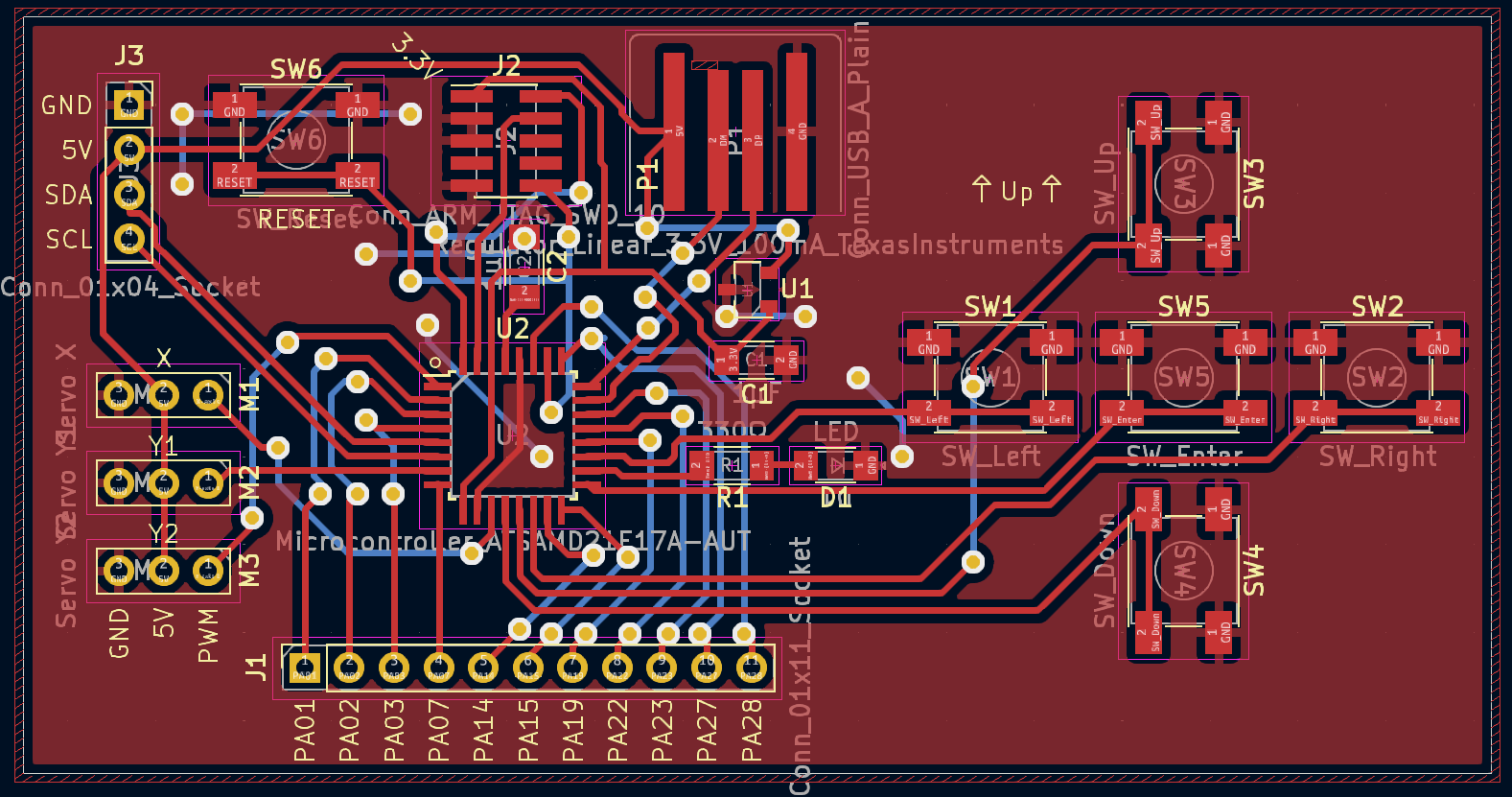
Now for routing. The up, down, left, right, and enter buttons want to be in specific positions relative to each other, and the USB receptacle wants to touch the edge of the board. Other than that, I arranged parts to try to minimize crossings and then started wiring things up. (Actually, I realized the wires were too thin, changed the design rules, and then started wiring.)
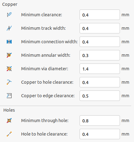
I added a flood fill region for GND and added a few vias needed to connect isolated GND regions. After that, I went to check the design rules, and got about 100 errors all regarding via hole size, because the vias were all too small. Oops! I had to go back and fix every single via.
The final PCB is shown below:
The files for the final schematic, PCB, and Gerber files are here.