05: Electronics Production
This week it’s time to actually make the board I designed!
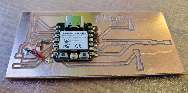
First of all, I was told that the ATSAMD21E was a suboptimal choice for performance. I changed the chip to a XIAO ESP32C3, which can operate at 160 MHz. (Whether I actually need that much speed is another story, though.). I also was told that vias were going to be a nuisance, so I removed them. (Yes, it was that simple. Changing the board to XIAO ESP32C3 drastically reduced the number of pin connections I needed (at the expense of also getting rid of the leftovers)).
Milling time!
Programming
After soldering on just the microcontroller, the resistor, and the LED, I wanted to test the LED to make sure it works. I used Arduino and made a simple test program borrowed from here:
const int LED = 3;

void setup() {
  pinMode(LED, OUTPUT);
}

void loop() {
  digitalWrite(LED, HIGH);
  delay(1000);
  digitalWrite(LED, LOW);
  delay(1000);
}
Unfortunately it didn’t compile, running into the following error:
Traceback (most recent call last):
  File "/home/hayastl/.arduino15/packages/esp32/tools/esptool_py/4.6/esptool.py", line 34, in <module>
    import esptool
  File "/home/hayastl/.arduino15/packages/esp32/tools/esptool_py/4.6/esptool/__init__.py", line 41, in <module>
    from esptool.cmds import (
  File "/home/hayastl/.arduino15/packages/esp32/tools/esptool_py/4.6/esptool/cmds.py", line 14, in <module>
    from .bin_image import ELFFile, ImageSegment, LoadFirmwareImage
  File "/home/hayastl/.arduino15/packages/esp32/tools/esptool_py/4.6/esptool/bin_image.py", line 14, in <module>
    from .loader import ESPLoader
  File "/home/hayastl/.arduino15/packages/esp32/tools/esptool_py/4.6/esptool/loader.py", line 30, in <module>
    import serial
ModuleNotFoundError: No module named 'serial'
exit status 1

Compilation error: exit status 1
Welcome to Electronics
Running pip3 install pyserial fixed that error. Try again, and it compiles, but the LED doesn’t light up. Turns out that it just happened to be in the disconnected GND region, so time to wire the two GND regions up.

Still didn’t work. Time to grab a multimeter and figure out why. A voltage check confirms that there is indeed a 5V difference between 5V and GND. And also that some pins have a 3.3V difference. Including pin D1, aka GPIO3. Turns out that the GPIO numbers are what’s relevant. Changing LED to 5 works… sometimes. And it seems to depend on the angle of the PCB. I tried using the multimeter, and then tried using the oscilloscope. I fumbled around the oscilloscope but at some point the microcontroller just stopped working entirely. Not even the charge light was on.
Using a multimeter again, it claims that the resistance across the resistor is around the correct value (499 Ω), but the resistance across both the resistor and the LED is like 0.1 Ω, the same as the resistance it claims between two different points in the outer GND region.
After asking for help, it seems like two of the joints were suboptimal, so I tried adding more sodor to them. It seems to work consistently now regardless of angle, but you never know. Also, apparently sometimes the multimeter lies.
Up, Up, Down, Down, Left, Right, Left, Right, Enter
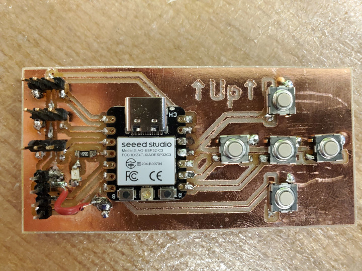
Time to add buttons! I added up, down, left, right, and enter buttons in the shape of a ‘+’. I then added some code to test those buttons. I was too lazy to figure out Serial at the time so I did what I could with one LED. The code loops through 6 phases: one for each button (turning the LED on iff that button is pressed) and a final delimiting phase where the LED is on 1/16 of the time.
const int LED = 5;
const int BUTTONS[] {10, 21, 8, 9, 20};
const int NUM_BUTTONS = sizeof(BUTTONS) / sizeof(int);

uint curr_time = 0;
uint mod_time = 0;

void setup() {
  pinMode(LED, OUTPUT);
  for (int i = 0; i < NUM_BUTTONS; ++i)
    pinMode(BUTTONS[i], INPUT_PULLUP);

  curr_time = micros();
}

void loop() {
  uint diff = micros() - curr_time;
  curr_time += diff;
  mod_time = (mod_time + diff) % (500000 * (NUM_BUTTONS + 1));
  int phase = mod_time / 500000;

  bool on = phase < NUM_BUTTONS ? !digitalRead(BUTTONS[phase]) : mod_time % 500000 / 1000 % 16 == 0;
  digitalWrite(LED, on);
}
Yay, it worked the first time!
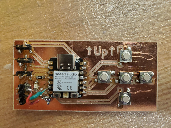
After that, I soldered in the headers for the servo motors and display. But when actually linking the display up, I noticed that SCL and SDA were wired switched. Great. Fixing that required a crossover, built with a raw wire and a jumper wire. Very annoying to solder. Also, some copper needed to be cut.


So now I tried to insert and program the display (by the way, I just used 4 connectors to do it, making that whole crossover process a waste of time. Whoops!), taking code from this example, but simplifying it greatly. It didn’t work.
Serial wasn’t working, making debugging hard. Looking online, there’s this setting called “USB CDC on Boot” that needs to be enabled for some ESP32s, which clearly includes mine since Serial worked after enabling it.
I tried using an oscilloscope and found out that I wasn’t getting a clock signal from SCL.
At some point Arduino stopped being able to upload to the XIAO ESP32C3 with A fatal error occurred: No serial data received. This was fixed by this solution, which was:
- press and hold the B button on the microcontroller
- press and release the R button
- release the B button after a second
- unplug and replug the microcontroller.
I have no idea what caused that problem.
I did an I2C test to see what was going on. At the beginning, I had:
Wire.begin();
and in the loop, I had something that transmitted a signal at repeated intervals:
if (phase != prev_phase) {
  Wire.beginTransmission(0x3c);
  Wire.write((const uint8_t*)"This is test text", 18);
  int result = Wire.endTransmission(true);
  Serial.printf("I2C result: %d\n", result);
}
This didn’t work. Until I changed that first line to Wire.begin(6, 7) (which is where SDA and SCL are, respectively), and I got a clock signal from SCL! Unfortunately, this means that that crossover was an even bigger waste of time since I could have just done Wire.begin(7, 6). Whoops.
Then on Saturday evening I got sick (probably from goofing up and drinking something spoiled), which lasted longer than expected and essentially took me out for a few days.
During that time, I didn’t feel like trying much, but I at least tried to find an ESP32 servo library. The ESP32 ESP32S2 AnalogWrite library looked promising, so I tried to incorporate it into my project, but it didn’t compile due to a recent (2024) breaking change to a dependency (ledc). Oh well.
Also, the top servo header on the board had a problem where it would peel off, requiring resoldering joints twice. The second time, the 5V line broke, requiring a third jumper wire. And jumper wires are very annoying to solder due to needing 3 hands.