BIG
For this week I wanted to make a grid of gadgets that a gear moves through and does logic. (Originally the plan was to make a divider by 10 and actuate a segment display based on that, but time ran out)
Scale Down
First, I designed some small 2-inch gadgets, starting with the wire, right turn, and left turn (and the turns aren’t symmetric). The gear diameter was 0.375 in, and it had 12 teeth. A rack that went across the gadget had 24 teeth. Since the gadget would be in 2 pieces, I needed a structure to hold the pieces together. The original design was done in FreeCAD.
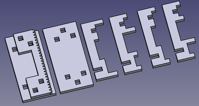

Getting the racks for the curves was tricky. I really wanted gears with a non-integer number of teeth (and now that I think of it, that would have been incorrect, given that I needed to do a 90° transition from the middle of a tooth to the middle of another tooth), but that wasn’t happening, so I chose the closest integers I could find. Apparently I chose one too big for the left turn. Internal gears are unforgiving.
However, a BIG problem showed up.
Joint Hell
There are slot joints and hole joints, and they both need to have just the right fit. Too loose and the gadget will come apart. Too tight and you can’t put it together in the first place. Since the gadget is laser cut, there’s also the variable kerf of the laser cutter to account for, and the fact that the bed isn’t flat, and the fact that the acrylic isn’t flat, the edge of the cut being a little rough, and the shape of a laser cut being slanted (wider on the top and narrower on the bottom). All this variation adds up to more than the distance between “too loose” and “too tight” for a joint, even when attempting to account for kerf. I have had many, many pieces fit too loosely or break when trying to fit them. And that’s after doing a joint fit test due to the variation mentioned above.
The parameters I found that worked initially were -0.08 mm of slot joint width expansion (so they contract) and 0.125 mm of hole joint hole width expansion. This was done on the bigger laser cutter in EDS with 100% power, 5.1% speed, and 1000 freq, with a kerf of 0.26mm. And they were pretty nice, if not a little tight. Except that I didn’t add corner cutouts (“dogbones”) so the corners were rounded by half the kerf and I was effectively trying to fit a square peg into a round hole for the hole joints.
Cutting Corners
So I added the dogbones. But first, I didn’t like how bloated the FreeCAD design was getting (with names like Extrude547) even when I tried to be as parametric as possible. So I moved it to Inkscape and designed the items in a rather interesting way. I used lines to indicate things like wire cutouts and fingers. (I also switched from a square holder to an X holder design. This was a mistake in terms of rigidity. However, it saved time and material in a time when time was precious.)

- Black: outline
- Green: wire cutout
- Blue: hole joint hole
- Yellow: other hole
- Dark blue: finger
- Pink: scaffolding cutout
- Light blue: extender (needed separately because of dogbone positioning implied by fingers)
- Red: slot joint
- Cyan: manual dogbone (unnecessary, but whatever)
- Purple: engraving (technically super-fast cutting)
I made a script using the Simple Inkscape Scripting extension to convert this into the actual shapes that would be cut. Except that scripting is limited, so I had some manual steps at the end:
- Select all light blue, dark blue, red, and green lines and convert strokes to paths
- Select all black, dark blue, and light blue shapes and union them
- Select all other shapes except cyan ones (the now actually circular dogbones) and purple ones (the engraving) and union them
- Difference the results of the above two
- Set stroke to red and hairline (to make it a vector operation), including the dogbones
- Offset the main shapes by half the kerf and the dogbones by negative half the kerf
Here’s the script:
from inkex.transforms import Vector2d, Transform

side_length = 4*inch
wire_thickness = 0.25*inch
sheet_thickness = 3*mm
hole_expansion = 0.04*mm
slot_expansion = -0.12*mm
boolean_clearance = 0.02*mm
dogbone_radius = 0.375*mm # must be at least laser cutter kerf / 2

def normalized(vec):
    return vec / vec.length

def extend(line, amount: float, end: bool):
    path = line._inkscape_obj.path.to_absolute().to_non_shorthand()
    points = list(path.end_points)
    first = 1 if end else 0
    path[first] = path[first].translate(normalized(points[1 - first] - points[first]) * -amount)
    line._inkscape_obj.set("d", path)

def add_line_dogbones(line, end: bool):
    thickness = line.style()["stroke_width"]
    points = list(line._inkscape_obj.path.end_points)
    if not end:
        points = points[::-1]
    dir = normalized(points[1] - points[0])
    perp = Transform("rotate(90)").apply_to_point(dir)
    scaled_perp = perp * thickness / 2
    extra_dogbones.append([points[1] + scaled_perp, -dir, -perp if end else perp])
    extra_dogbones.append([points[1] - scaled_perp, -dir, perp if end else -perp])

shapes = selected_shapes()
extra_dogbones = []

# Holes
holes = [s for s in shapes if s.style()["fill"] in ["#0000ff", "#ff8000"]]
for hole in holes:
    if hole.style()["fill"] != "#ff8000":
        hole.scale((sheet_thickness + hole_expansion) / sheet_thickness, "c", first=True)
    points = list(hole._inkscape_obj.path.transform(hole._inkscape_obj.composed_transform()).end_points)
    points.append(points[1])
    for p0, p1, p2 in zip(points, points[1:], points[2:]):
        extra_dogbones.append([p1, p0 - p1, p2 - p1])

# Fingers
fingers = [s for s in shapes if s.style()["stroke"] == "#000080"]
for finger in fingers:
    if finger.style()["stroke_dasharray"] != "none":
        points = list(finger._inkscape_obj.path.end_points)
        extend(finger, (points[1] - points[0]).length * (-1 + 3*mm / (0.125*inch)), True)
    finger.style(stroke_dasharray="none", marker_end="none")
    extend(finger, boolean_clearance, False)
    add_line_dogbones(finger, False)

# Slots
slots = [s for s in shapes if s.style()["stroke"] in ["#ff0000", "#ff8000"]]
for slot in slots:
    if slot.style()["stroke"] != "#ff8000":
        slot.style(stroke_width = slot.style()["stroke_width"] + slot_expansion)
    slot.style(marker_end="none")
    extend(slot, boolean_clearance, False)
    add_line_dogbones(slot, True)

# Dogbones
def add_dogbone(point, dir0, dir1):
    bisector = normalized(dir0 + dir1)
    pos = point + bisector * dogbone_radius
    dogbone = circle(pos, dogbone_radius)
    dogbone.style(fill="none", stroke="#00ffff", stroke_width=0.01*inch)

corners = [s for s in shapes if s.style()["fill"] == "#00ffff"]
for corner in corners:
    points = list(corner._inkscape_obj.path.end_points)
    add_dogbone(points[1], points[0] - points[1], points[2] - points[1])
    corner.remove()

for extra in extra_dogbones:
    add_dogbone(*extra)
This would be simpler if I could include the dogbones in the difference operation, but unfortunately Inkscape is inaccurate with them and tends to produce results like this:

So the dogbones have to be cut separately.
Joint Hell 2
…and my luck ran out with the joints. To be fair, I switched laser cutters to the big one in Metropolis for a time. With the same parameters, after accounting for its kerf, the joints were too loose. Which was to be expected, since now there are dogbones, but it’s still annoying. More joint testing. Ugh.
Frame Grid
I mentioned scaffolding briefly. This is what the frame grid is for. It’s a grid made of 12 edges crossing 12 edges, resulting in an 11×11 array of cells. This was also designed in Inkscape using the same design method.
