08: Stepper Motors
Now to get some stepper motors working.
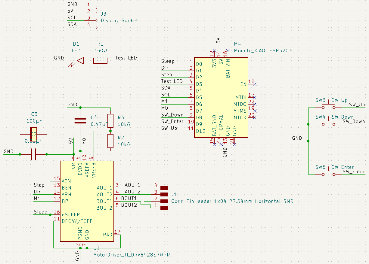
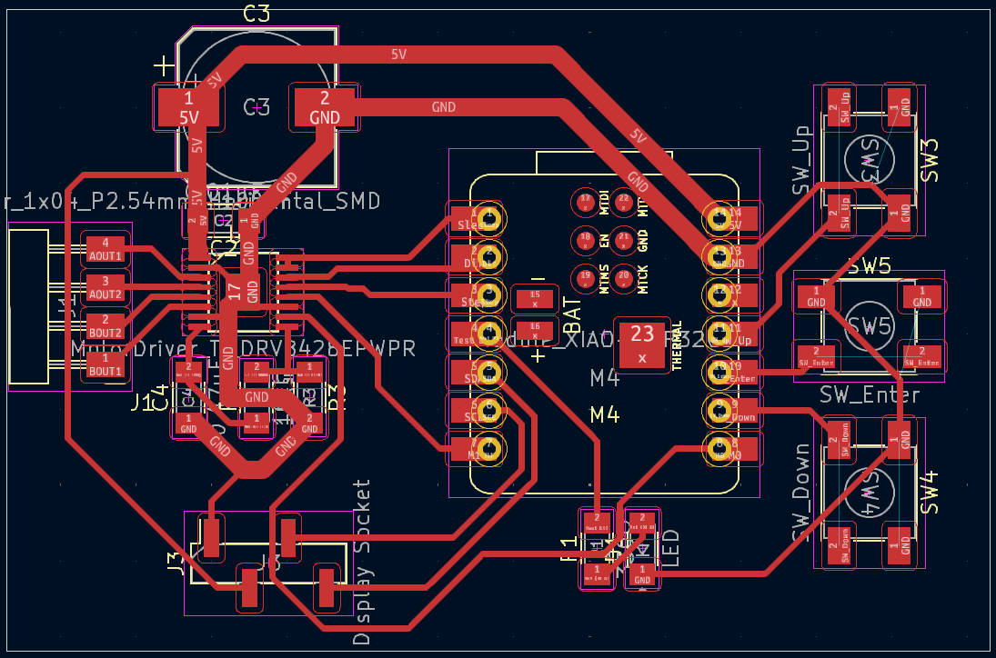
I used the DRV8428 stepper motor driver with a NEMA17 stepper motor. First of all, according to this table, a wire diameter of 0.4mm can only handle 0.361A for power. The DRV8428 can potentially draw 1A, so the 5V and GND wires going there need to be thicker. I made them 1.2mm thick. Also, I want to eventually get 2 stepper motors working, but first I should get 1 stepper motor working, and I decided to make a test board for that. With that in mind, here’s the test board design:
Tiny Component, Big Problems
And then problems came immediately. The pins on the DRV8428 are 0.4mm thick and the space between them is 0.25mm thick, according to the fab library footprint. So this already violates the design rule that 0.4mm is the minimum trace clearance. My options were to use the super secret 0.01” flat end mill (which wasn’t really super secret since I saw one of them) or use an engraving bit. I chose the engraving bit (30°, 0.003in) because I heard that the 0.01” flat end mill is super delicate. This turned out to be fine.
But there’s another problem: soldering the component with the tiny pins. I tried 2 times with the solder paste and both times there were bridges. After asking Anthony for help, I learned that the trick is to go ahead and use solder paste, then for each side, use solder wick on that side to remove bridges and use a regular soldering iron to carefully add solder to each pin.
Step, Step, Step, Blackout
After soldering all the components, I added some test code that just spins the stepper motor. Getting that test code working properly took a few tries. Here is the initialization code:
pinMode(Stepper::EN, OUTPUT);
pinMode(Stepper::STEP, OUTPUT);
pinMode(Stepper::DIR, OUTPUT);
digitalWrite(Stepper::STEP, 0);
digitalWrite(Stepper::DIR, 0);
digitalWrite(Stepper::EN, 1);
pinMode(Stepper::M0, OUTPUT);
pinMode(Stepper::M1, OUTPUT);
digitalWrite(Stepper::M0, 0);
digitalWrite(Stepper::M1, 0);
And the stepping code:
uint diff = micros() - curr_time;
curr_time += diff;
uint prev_mod_time = mod_time;
mod_time = (mod_time + diff) % 1000;
if (mod_time < prev_mod_time) {
  digitalWrite(Stepper::STEP, 1);
  delayMicroseconds(10);
  digitalWrite(Stepper::STEP, 0);
}
The important thing here is that the stepper motor steps whenever the STEP pin changes from low to high.
In the meantime, I accidentally turned an OLED display into a heater. I wanted to use the white OLED display instead of the yellow-blue one I’ve been using before. Unfortunately, for whatever reason VCC and GND are switched on the white OLED. You can guess what happened. I’ll make sure to swap VCC and GND for the display on the real board.
One heated display and resigning to using a yellow-blue display later, the stepper motor stepped! Until one time I plugged in the USB to my computer and the board and my computer instantly shut down.
Too Much Current
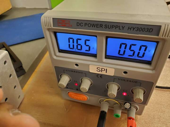
Turns out that USB C only supports 0.5A and the stepper motor was drawing more than that. So I needed a better power supply. And a way to get that power supply to attach to the board. For power, I used an HY3003D bench DC power supply. I just attached a 2×2 pin header to a region where a 5V trace and a GND trace are parallel and at the right distance from each other, followed by adding a 2-wire adapter so that there’s enough room for the alligator clips to clip to the wires and not short 5V to GND.
Also, I had the polarized capacitor wired backwards because I mixed up which trace was 5V and which trace was GND. So that needed fixing too. I got a new capacitor because Anthony said so just in case. After looking up what happens, apparently they can explode, so I got super lucky that everything looked fine.
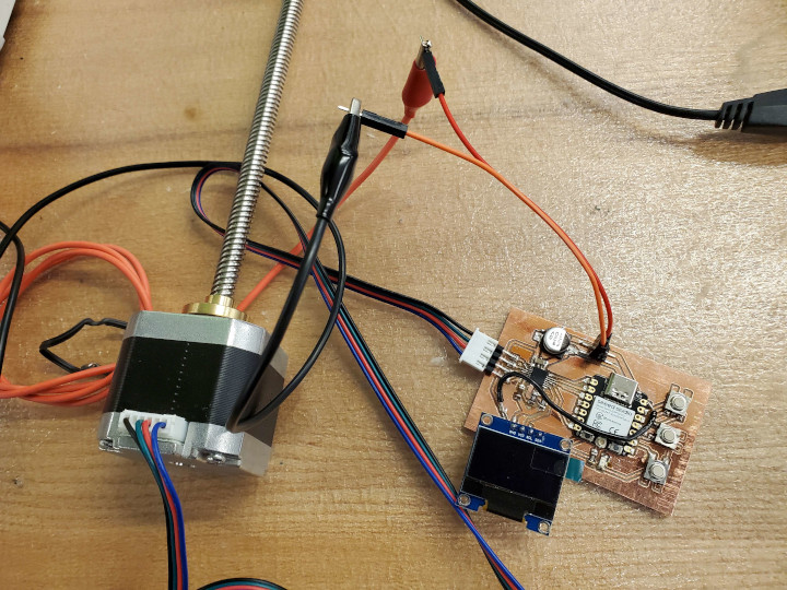
Notice the unexplained black jumper wire from 5V to the display’s VCC. This happened because I was originally planning to plug in both external power and the USB for data transfer at the same time, and after a quick Falstad simulation I don’t want to have them share both 5V and GND. So I was going to isolate the stepper motor’s 5V (which happened to be bridging the microcontroller’s 5V and the display’s VCC). This ended up not happening as I found a workflow that doesn’t involve plugging in both external power and the USB at the same time. Surely I won’t forget to do things in the correct order.
To upload code,
- turn the external power off
- unplug the stepper motor
- plug in the USB.
To test the system, the above steps should be followed in reverse.
Anyway, here’s the stepper motor in action (it’s microstepping here because I changed the code)
Axis and No Angle
Now to make a linear actuator. This requires designing the holder for the stepper motor, and a jig that forces whatever’s attached to the leadscrew on the stepper motor to not rotate. If it can’t rotate, it must travel in a straight line whenever the leadscrew rotates.
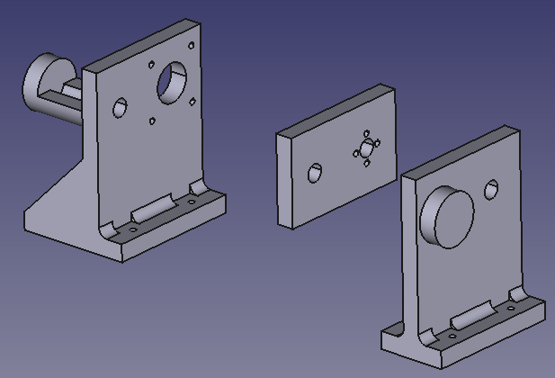
These got 3D printed.
For attachment, I used R4-40 3/4” screws. For the stepper motor, I also added two R4-40 nuts per screw because the screws would be too long otherwise (and the next largest size was 1/2”, which would be too short). I had to file some of the holes because some fits were tighter than expected (though in retrospect, I filed down the hole in the jig that the metal rod goes through because there is some backlash).
After adding code that moves the stepper motor backwards if a button is held, this is the result:
Perhaps the metal rods could use a lathe. They look a little dirty on the outside, ruining my judgement of whether I’ve filed the hole enough or not. But whatever.
Time ran out, and more importantly I got distracted by a different making project, so I didn’t get around to the real board.
The test board design files are here