Advanced Machine Usage
…in which I talk about machine uses we didn’t touch in HTMAA.
Multi-color 3D Printing
…using a Prusa MK4 with only a single extruder
EDS has 2 Prusa MK4(now MK4S) 3D printers. Unfortunately, they don’t have multiple extruders. EDS also has a Bambu 3D printer, but I wasn’t used to it and didn’t want to deal with new problems during final project crunch. As it turns out, a Prusa MK4 can simulate multiple extruders with a single extruder (source):
- Under Printer Settings > General, set the number of extruders to 2 and check Single Extruder Multi Material.
- Under Printer Settings > Custom G-code > Tool Change G-code, type
M600. This triggers the manual filament change process. - Set the correct extruders for your parts (In the plate view, in the section on the right, left double click the appropriate entry in the Extruder column and select the correct filament)
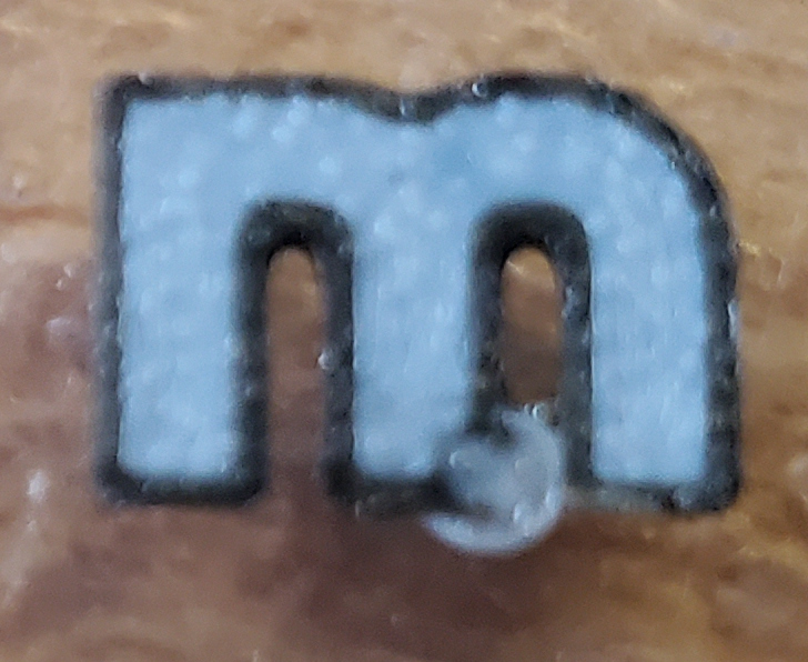
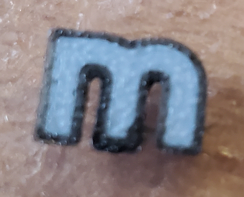
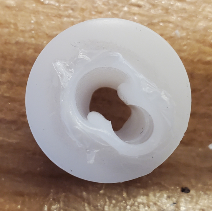
- Under Print Settings > Multiple Extruders, turn off the Wipe Tower. If you leave it on, the 3D printer will prematurely start unloading filament while still printing the wipe tower, which causes problems during filament change. Specifically, the filament gets stuck. Half the time you can open up the idler, push the filament down, and nip the bulby tip off, and all is well. But half the time, you can’t move the filament up or down, and have to take the whole structure apart and cancel the print. So, no wipe tower.
Since there’s no wipe tower, you’ll have to prepare a part to sacrifice to the gods of nozzle unparking. Unfortunately, I have not quite figured out the ritual (putting the sacrifice in the right place so that it prints last in each layer), so you have have to pray.
It’s probably possible to set things up so the unparking location is in an out-of-the-way place every time, but I didn’t bother.
When actually 3D printing, every filament change must be done manually. So don’t give yourself too many or you’ll regret it.
Low-Extrusion-Width 3D Printing
…using a Prusa MK4 with a 0.4mm nozzle, with extrusion width 0.2mm
This allows for printing thinner details than usual.
- Under Print Settings > TODO, set the extrusion widths of all types to 0.2mm.
There’s a couple of complications with this, though:
- You have another god to sacrifice to: the god of lingering extrusion. And it’s more demanding of sacrifices. Whenever the extruder moves a long distance, or moves to print the first part, some already extruded filament gets squished and takes up the full 0.4mm width of the nozzle.
- You really need a clean flat bed. If the probing process does anything funky (like probe multiple points in the same small area), you’re screwed. Without a clean flat bed, you can end up with a very thin first layer. (TODO: picture)

Milling Cast Acrylic
…with a PCB mill, specifically the Othermill V2
EDS has a desktop PCB mill called the Othermill V2 (along with a Roland SRM-20 and a cheap Lunyee mill). I specifically used the Othermill because it has the highest spindle speed (allowing for higher feeds), maxing out at 16400 RPM. The Roland SRM-20 maxes out at 7000 RPM, a big drop. The Lunyee mill theoretically maxes out at 12000 RPM, which would have been fine, except that no it doesn’t. I didn’t have the tool to measure the spindle speed, but that did not sound like 12000 RPM, whether milling or just spinning in air.
Feeds and speeds I use for cast acrylic:
| End mill | Spindle speed (RPM) | Horizontal speed (in/min) | Plunge/ramp speed (in/min) | Stepdown (in) |
|---|---|---|---|---|
| 1/8” flat | 16400 | 60 | 20 | 1/32 |
| 3/32” flat | 16400 | 60 | 20 | 1/32 |
| 1/16” ball | 16400 | 44 | 20 | 1/32 |
| 1/32” flat | 16400 | 32 | 16 | 1/64 |
| 1/64” flat | 12000 | 24 | 8 | 1/128 |
| 30° 0.1mm-tip engraving | 16400 | 60 | 20 | n/a |
Stepover is half the tool diameter. In the case of the engraving bit, stepover is design-dependent. I don’t use a stepdown of more than 1/32”, even for the 1/8” and 3/32” end mills, because I’ve encountered severe dimensional inaccuracy issues with too big of a depth. But maybe that’s just because I was using the Lunyee at the time with its suspicious spindle speed.
Anyway, the process goes like this:
- If you’re using Fusion 360, you postprocess with the Bantam Tools postprocessor, making sure to enable M6 for tool changes. If you’re using FreeCAD, I haven’t figured out the process yet.
- Open Bantam Tools and home the machine
- Measure the thickness of the acrylic with a caliper. Unfortunately I’ve encounted thicknesses from 2.75mm to 3.1mm for cast acrylic that claims to be 3mm or 3.175mm thick.
- Place the acrylic in the machine using double-sided tape. (I used 3M tape that had a green plaid backing and was 0.24mm thick.)
- Enter the size and thickness of the material
- Load the file resulting from the postprocessor and set its position.
- Mill!
2-sided milling
2-sided milling is more complicated because you have to get the alignment right. You also have an underside and topside toolpath to deal with.
The process:
- Make sure the underside and topside toolpath have the same origin. The underside should have a flipped Z-axis and flipped X-axis relative to the topside.
- For each of the underside and topside toolpaths, select the relevant toolpaths and set up a rotation pattern:
- Make sure the axis for the underside and topside toolpaths agree and go through the shared origin.
- The angle will be set later. For now, just create the pattern.
- Make sure your acrylic piece is a right rectangular prism, not an oblique one. If you just laser cut a rectangle out of acrylic, the result will be an oblique rectangular prism due to the cut being narrower on the bottom than on the top. You could trim the rectangle with a mill to fix this.
- Attach and locate the alignment bracket.
- Drop down the G-code status and pay attention to the bracket rotation. Let’s call it \(\theta\).
- Go back to Fusion and rotate the underside toolpath by \(-\theta\) (note: negative!) and the topside toolpath by \(\theta\).
-
Postprocess the underside and topside toolpaths separately.
- Place the acrylic in the machine, aligning it to the right side of the alignment bracket.
- Set the alignment to the right side in the software as well.
- Load the underside toolpath, place it appropriately, and mill. Call the material width \(w\), material thickness \(h\), and toolpath placement \(\langle x_u, y_u, z_u\rangle\)
- Flip the acrylic, aligning it to the left side.
- Set the alignment to the left side in software.
- Load the topside toolpath, place it at \(\langle w - x_u, y_u, -h - z_u\rangle\), and mill.