Final Project
For my final project, I want to make a laser cutter, except that instead of using a laser to cut things it puts sprinkles on cookies and cakes.
During electronics simulation week, I modelled a movement system that takes a shape file from an SD card as input, posted here
During 3D printing week, I made a 2-axis control 3D print (with a detachable funnel!). Turns out that torque is a thing and one of the axis would need 2 motors. Posted here
During input devices week, I made a touchpad out of magnet sensors. I decided I want to include a drawing input method for the sprinkler machine, and this was a good place to attempt to make one. Posted here
Welp, I got very inspired by what I decided to do for BIG week, and now I want to turn that into a final project. Besides, no need to worry about food safety.
The basic idea is the same: a gear doing logic. This time, each gadget will have electronics involved in them such as lights to display the type of gadget and the state the gadget is in (for ones with states, such as switches) and sensors to detect the state that switches are in. (Unfortunately there will not be motors to move the switches because motors are expensive and this wouldn’t scale well.) The player gear is controlled by a motor that automatically moves it around the field. Each gadget is connected to a frame that carries electricity to it. (Or I could figure out connecting electricity between gadgets directly.)
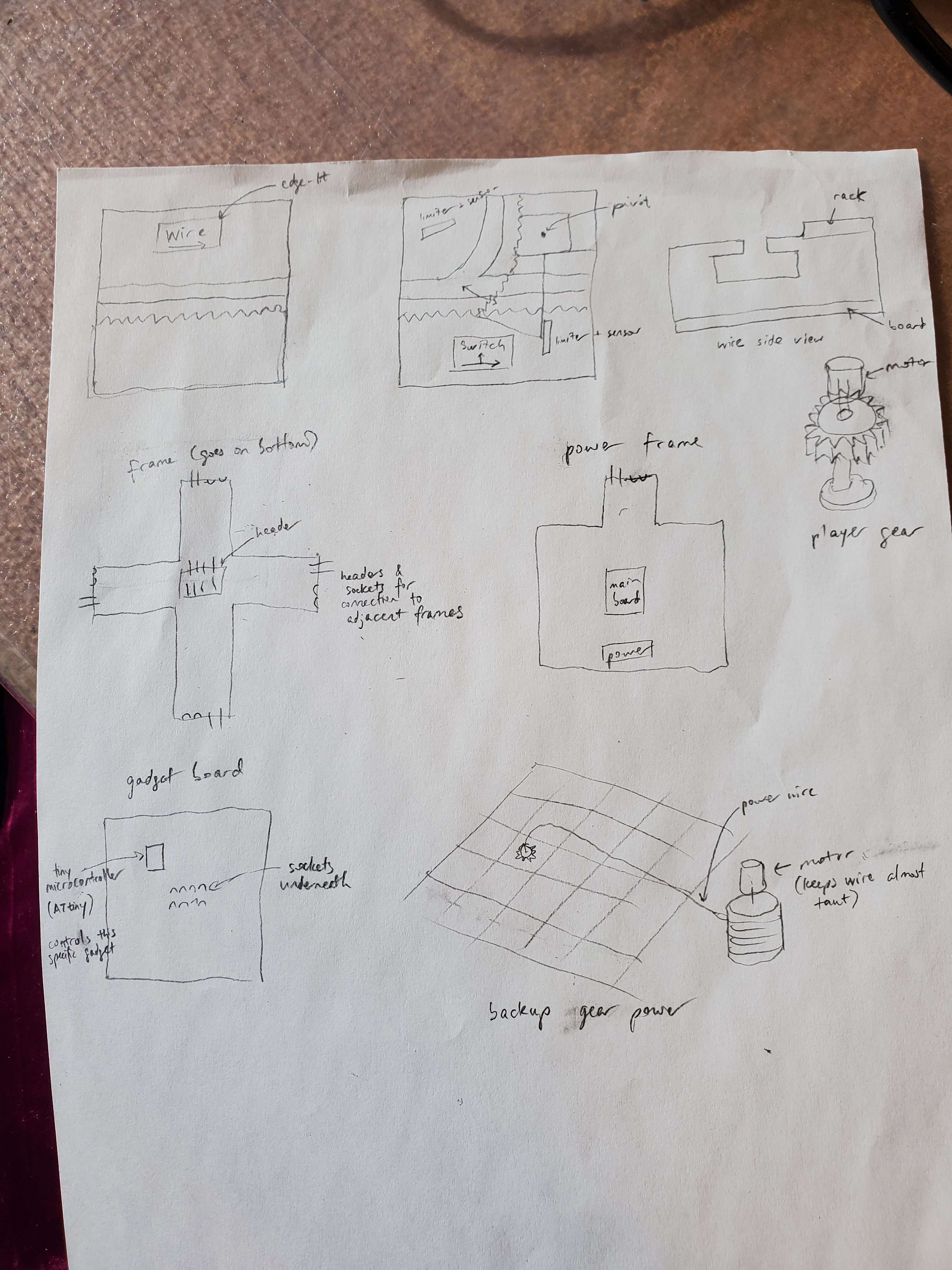
Schedule:
- Experiment with train model, direct transmission of power (to player gear/train) via gadget grid, direct connection of adjacent gadgets (before 11/25)
- Build wire and switch gadgets and measure various parameters (power, current, etc.) to see how well they’ll scale (before 12/1)
- Scale, scale, scale up as much as possible
Getting Logical about Complexity
It turns out, though, that thinking about the many problems that came up (including microcontroller communication without overwhelming a microcontroller and powering the player gear), and also realizing that it takes way too many gadgets to simulate an AND gate (about 30-ish when I checked), I decided to scale down and just make gadgets that take some inputs, do some computation with them, and output outputs. No worrying about player-gear-related stuff.
The Logic of the Logic
The basic way this works is that each gadget is a square that has 4 inputs/outputs, one on each side. Some gadgets have additional inputs/outputs such as switches or displays. Each gadget is fed a clock signal from the master of clocks (the main board). On a clock rise, the gadget takes all its inputs, does some computation, waits a bit (so that all gadgets appear to read their inputs at the same time), and outputs the result.
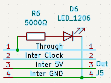
LEDs are used to show progression of logic. A wire is a connection from a gadget’s output to the adjacent gadget’s input. Each side of the wire (output, connector, input) is lit with a separate LED. I went through several iterations about how to light up a wire properly.
(In the schematics below, all resistors are 5000Ω. This should keep the LEDs sufficiently bright while not consuming too much current. Assuming 3.3V input, an LED would then consume 0.66mA of current at most, making it take about 1500 LEDs to consume 1A.)
- Left: one LED line for the output side (containing 2 LEDs) and one LED line for the input side. I decided not to go with this due to the lack of symmetry, which could cause the line of 2 LEDs to be darker than the line of 1 LED.
- Middle: one long LED line. This didn’t work. Turns out that I forgot that LEDs need their due voltage.
- Right: three parallel LED lines. And it’s nice and symmetric. The only difference between an input and an output is the color of the LEDs. This allows for making more general boards. (Unfortunately it requires more resistors.) This is the one I ended up going with.
First, I’ll go over the evolution of the process and problems that occured. Then I’ll get into more detail about reproduction.
Boarding the Logic
To actually make the boards, there are several considerations that need to be considered:
- Powering the boards through the network
- Timing the boards
- How outputs are connected to inputs
- The microcontroller that will be used (an ATtiny1624 because it has enough pins while not being too expensive)
- Current consumption
First, I started off with designing the OR-IIOO gadget (OR gate with 2 adjacent inputs and 2 outputs).
Design 1: Awkward Angles
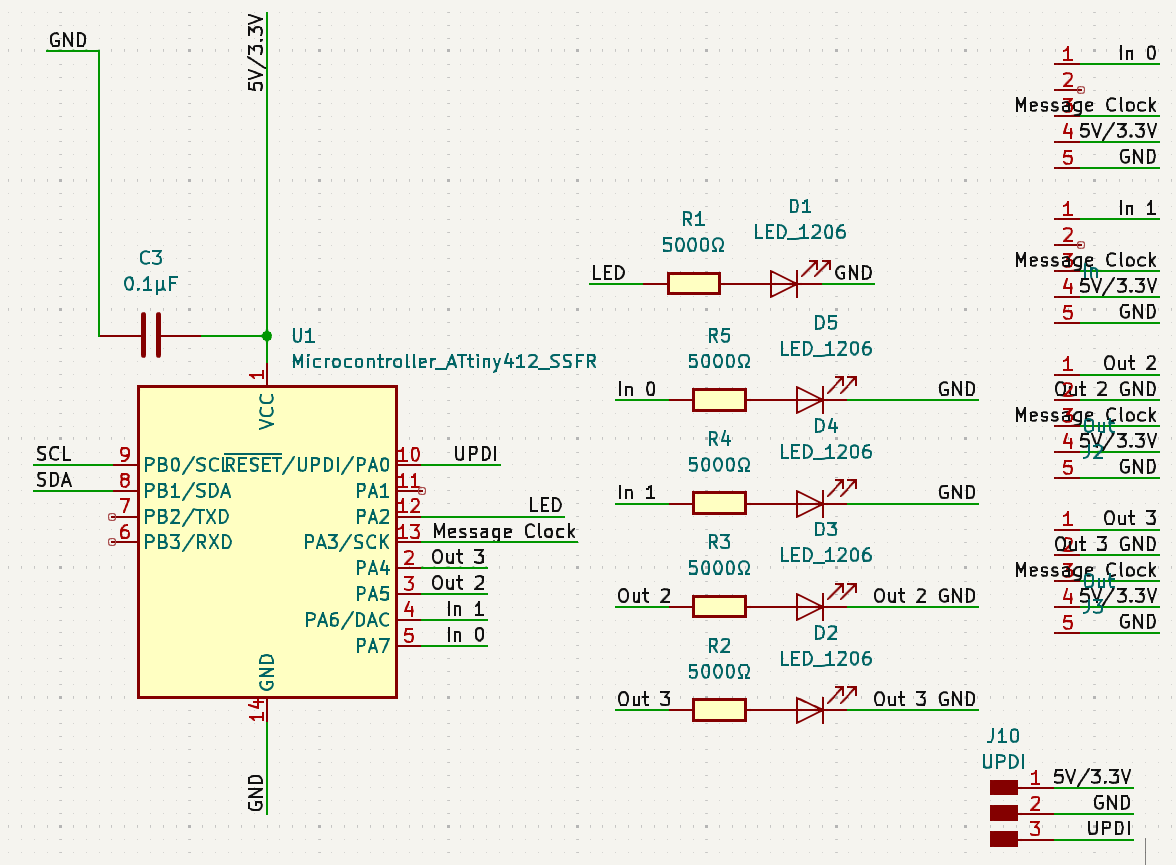
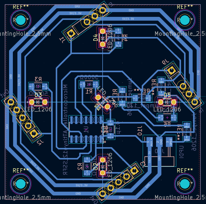
In this design:
- The microcontroller can take 5V or 3.3V depending on whether it’s connected to power directly (via the UPDI pin header) or through the network from some voltage-regulated board.
- Boards expose sockets (4 for each input, 5 for each output). Adjacent boards are connected using a connector (shown below) to connect their ground, power, clock, and output-input lines together.
- There’s an extra (white) LED that turns on when the result of the computation is “true”.
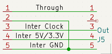
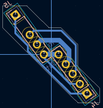
The connector just connects corresponding ports together, except that the line that went through the output LED gets connected to ground. This ensures that an output LED can’t light up if it’s not connected anywhere. In retrospect, this was a bad feature, because it would make debugging harder. I say “would”, because I didn’t actually make this board. The shape of the connector is even more awkward than the angles and just looks unwieldy and too long and thin.
Design -1: Generalizing the Board
I went through a few more iterations, including the LED schematics shown way above. I arrived at a nice symmetric pattern.
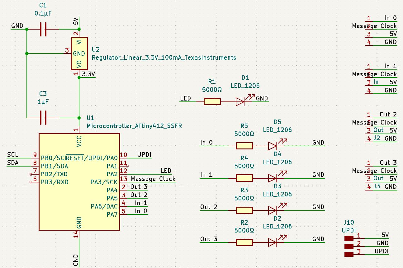
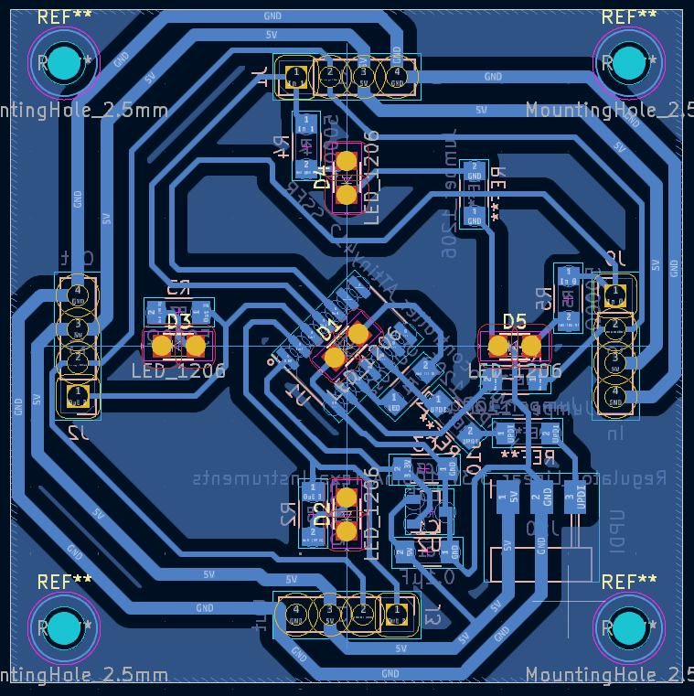
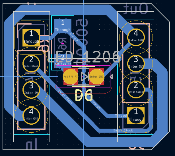
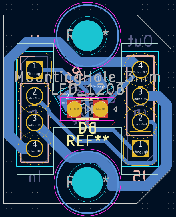
The new design changes several things:
- Inputs and outputs are symmetric, so I might as well name them like they’re symmetric. (They were technically symmetric in the first design too, but intermediate designs broke symmetry.)
- Outputs connect directly to ground after going through an LED. This means that an output LED can light up even if the output isn’t connected to anything. This also means that output connections need only 4 pins instead of 5.
- The holes are bigger. They’re meant to fit the bulky part of IC sockets. IC sockets are nice because the bottom part of an IC socket is a pin that can fit into the socket. If it wasn’t for that, I’d have to use surface-mount pins in the connector (unstable) or mill on the other (top) side of the connector (ew) or use vias (time intensive).
- There’s a fill-in zone. This will be talked about later.
Making the Board
Then came actually making the board.
The board (the first of many, many boards) was milled with an Othermill V2 with
- a 1/64” end mill, 24 in/min, 0.15mm stepdown, 45% stepover (nicknamed [1/64” Please Step Over])
- a 1/32” end mill with default settings
To help with deburring, there’s an aforementioned fill-in zone. It turns out that the 1/32” end mill tends to cut better when climb cutting than conventional cutting. It climb cuts traces. But in doing so, it slots, and therefore leaves a conventional-cut edge exposed and ready to wreak copper-string-shaped havoc. The fill-in zone (clearance 1mm) ensures that no place on the board is farther than twice the tool diameter away from a trace, ensuring that there are no conventional-cut edges. Except that if the space between traces is the tool diameter, you get climb-cut edges intersecting with conventional-cut edges and they don’t get cleaned up. So I still have to deburr, because I don’t feel like messing with all the wires that I so carefully placed with 0.8mm spacing to pack wires while minimizing the use of the 1/64” tool.
Speaking of which, the [1/64” Please Step Over] was made because the default settings are unnecessarily slow, doing 2 passes with 0.1mm stepdown and a very inefficient 15% stepover.
Assembling the Board
Then came assembly. When the board and connectors are assembled, then before any adjustments, the end result should look something like this:
All LEDs have the same elevation, which is important. So I need to figure out how much to elevate the orange LED above the connector board, and use that, and the elevation of the connector board above the gadget board, to figure out the elevation of the other LEDs above the gadget board.
Let’s first take a nice look at an IC socket.
IC sockets are used as an interface for a connector board to connect to a gadget board. They are also used to hold LEDs.
The pin and cone of an IC socket fits into the holder of another IC socket, leaving only the buffer exposed between holders. The connector board will have just an exposed holder on top for the LED to be attached to. It also gets stacked on top of the gadget board. So the gadget board needs to elevate its LEDs 2 holders and a buffer over the top of the board. This can be done by just using a stack of two IC sockets instead of just one.
There’s a collision. I decided to deal with it by milling an H-shaped hole on the top side (not the bottom side! That side has copper.) with a 3/32” end mill. Digging 0.9mm deep is more than enough to clear the collision.
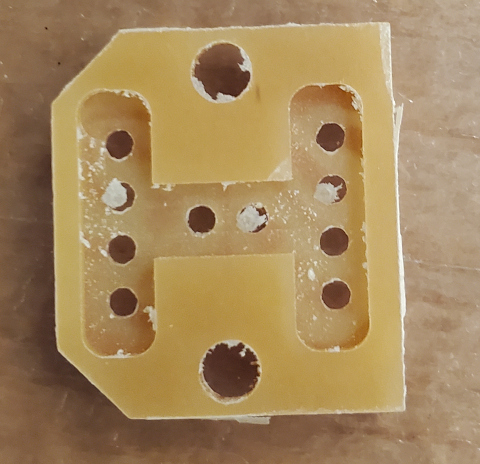
So with that out of the way, time for actually assembling the board. Of course, this didn’t go without a hitch.
- Assembly takes a while in general. The gadget board takes 30 minutes. And it’s the first of many.
- The buffer of an IC socket is barely shorter than the board is thick. So the connections to IC sockets have to be bridged when soldering. This got annoying, and I occasionally burned some traces trying to get solder to bridge. I didn’t change the design, because I was already in scale, scale, scale mode.
- Putting the microcontroller on top of the other side of an IC socket means that I had to trim the pins on that IC socket. Not trimming them sufficiently means having to bridge connections to the microcontroller. Trimming too much can peel off a trace.
- Hot iron reflow occasionally fails to connect one side of a resistor or capacitor, requiring manually resoldering to fix it.
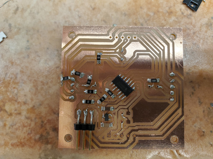
But finally,
Programming the Logic
I looked at this section to figure out programming for the ATtiny1624. I used the second schematic under “Ideal - internal resistor in the adapter - not more than 1k”, because the first one would use up a lot more resistors when scaling. I wired a breadboard and borrowed a USB to FTDI adapter because I wanted to hurry up and get to loading a program on the board. Except that the Schottky diode didn’t work. Replacing it with a 4700Ω resistor worked. (Though whether that diode was a Schottky diode is unclear.)
First of all, the ATtiny1624 receives 3.3V. According to the datasheet §33.3, the CPU clock should not operate at 20MHz at 3.3V. 10MHz is fine, so we should divide the clock.
// divide the clock by 2 to ensure safety with 3.3V
CCP = CCP_IOREG_gc; // needed because MCLKCTRLB is protected
CLKCTRL.MCLKCTRLB = 0b00000001;
This also affects the delay() function, so we have
#define real_delay(x) delay((x) / 2)
#define real_delayMicroseconds(x) delayMicroseconds((x) / 2)
First, I wrote a test program that turns on all the LEDs to make sure that they work. This is very important, because sometimes an IC socket solder bridge isn’t a bridge. Or the LEDs aren’t soldered to the IC sockets properly.
Then I wrote the actual logic for the board. In general, as said before, the gadget should wait for an external clock signal, read its inputs, do some computation, wait a little, and write its outputs. These inputs and outputs are assigned to ports A7, A6, A5, and A4 on the microcontroller. In the case of the OR-IIOO gadget, the inputs are A7 and A6 and the outputs are A5 and A4. The code looks something like this:
// ...
// Clock interrupt
PORTA.PINCTRL(3) = (PORTA.PINCTRL(3) & ~PORT_ISC_gm) | PORT_ISC_RISING_gc; // interrupt on rising edge of clock
CPUINT.LVL1VEC = PORTA_PORT_vect_num; // make it high priority
sei(); // enable interrupts
// ...
//
// (in interrupt handler) Logic
ISR(PORTA_PORT_vect) {
    // disable pin interrupt to avoid buffering interrupts (this was for networking week. Probably unnecessary here due to there being only 1 clock signal per clock cycle.)
    MSG_CLOCK_PORT.PINCTRL(MSG_CLOCK_PIN) = (MSG_CLOCK_PORT.PINCTRL(MSG_CLOCK_PIN) & ~PORT_ISC_gm) | PORT_ISC_INTDISABLE_gc;
    uint8_t flags = MSG_CLOCK_PORT.INTFLAGS;
    MSG_CLOCK_PORT.INTFLAGS = flags;

    uint8_t input = PORTA.IN & 0b11110000; // read inputs
    asm volatile( // wait like 32 cycles
        "nop \n" "nop \n" "nop \n" "nop \n" "nop \n" "nop \n" "nop \n" "nop \n"
        "nop \n" "nop \n" "nop \n" "nop \n" "nop \n" "nop \n" "nop \n" "nop \n"
        "nop \n" "nop \n" "nop \n" "nop \n" "nop \n" "nop \n" "nop \n" "nop \n"
        "nop \n" "nop \n" "nop \n" "nop \n" "nop \n" "nop \n" "nop \n" "nop \n"
    );
    // Write outputs
    bool output = input & (1 << 6 | 1 << 7);
    PORTA.OUTCLR = 1 << 2 | 1 << 5 | 1 << 4;
    PORTA.OUTSET = output << 2 | output << 5 | output << 4;

    // Re-enable pin interrupt
    MSG_CLOCK_PORT.PINCTRL(MSG_CLOCK_PIN) = (MSG_CLOCK_PORT.PINCTRL(MSG_CLOCK_PIN) & ~PORT_ISC_gm) | PORT_ISC_RISING_gc;
}
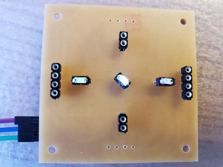
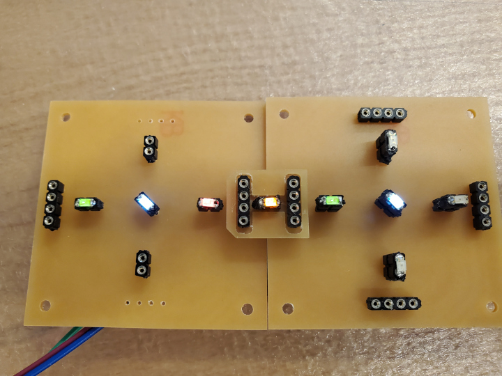
Decorating the Logic
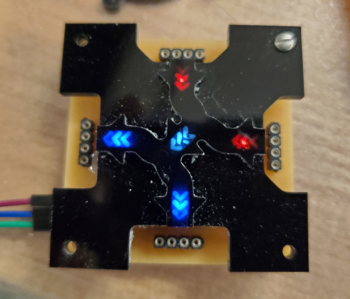
Well, now it’s time to put some decoration on top to show what the gadget does. Here’s an example
I wanted to elevate the path above the background, so I needed a 3D model. There’s a slab, and there’s the elevated path that goes on top of the slab. First, I sketched the paths in Inkscape. I used a trick for the path edges involving an arc path offset of -1/64”, then an arc path offset of 1/32”, then an arc path offset of -1/64”. This results in a path that a 1/32” end mill can mill from either the inside (for the slab) or the outside (for the elevated path). (Or at least it would, if Inkscape was a perfectly accurate program and didn’t mess up those path offsets. Usually, it’s just fine, but some inspection may be required.)
There are also mounting holes and holes for the connectors to fit in.
Then I imported it into FreeCAD and did appropriate operations to get the 3D models.
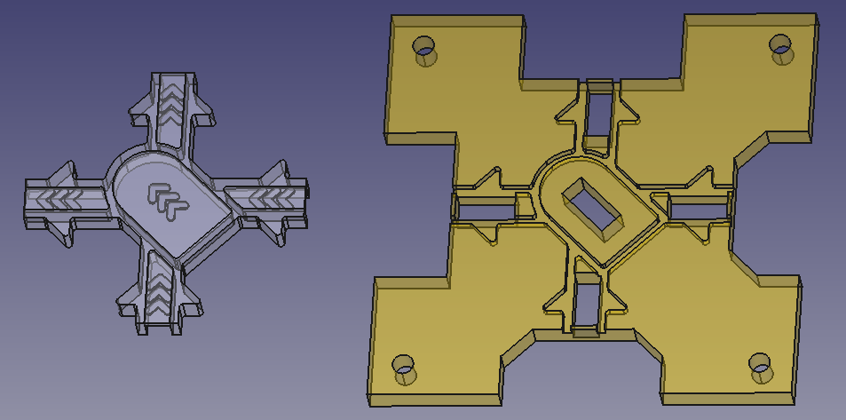
Note that the chevron holes don’t go all the way through. This is because of a serendipity that I found that will be explained soon.
Then I took that and imported it into Fusion 360 for CAM and generated the appropriate operations using the 3/32” flat end mill and the 1/32” flat end mill. (will be described much later). And then it was milling time. While milling an earlier design that didn’t have the black part of the Inkscape sketch above, because of an onion skin I set up, I found out that very thin black acrylic has nice frosty properties that let diffuse light through. Perfect for the LEDs. This is why the chevron holes don’t go all the way through: so they can take advantage of this property.
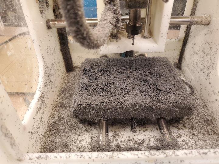


Then with some 2-56 screws and two 4-40 nuts per screw for spacing, I attached the decoration to the board.
Scale Up the Logic!
So now that I have something working, it’s time to scale up! Which means
- More gadgets
- More types of gadgets
Types of Gadgets (and Counts)
Logic Gadgets
- 4x OR-IIOO (Takes 2 adjacent inputs, ORs them, writes to 2 adjacent outputs)
- 4x AND-IIOO (Takes 2 adjacent inputs, ANDs them, writes to 2 adjacent outputs)
- 4x XOR-IIOO (Takes 2 adjacent inputs, XORs them, writes to 2 adjacent outputs)
- 4x Crossover (Takes 2 adjacent inputs and sends each one straight across. No more planarity!)
- 4x NOT-Straight (Takes an input, NOTs it, and sends that straight across)
- 4x Delay-16-Straight (Takes an input, waits a configurable number of cycles (up to 15), and sends it straight across)
- 4x Mux-LHSO (Takes inputs S, L, and H. Outputs H if S is high and L otherwise. Order is L, H, S, O counterclockwise.)
- 4x Split-OIO (Takes an input and sends it left and right. Implements both directions of turning.)
- 4x Memory-IWO (Takes inputs W and I. Outputs I (and stores it) if W is high and outputs the value it has stored in memory otherwise. Order is I, W, O counterclockwise and adjacent.)
- 4x 0-Delay-Straight (Takes an input and sends it straight across without propagation delay)
- 4x 0-Delay-Turn (Takes an input and turns it without propagation delay)
Input Gadgets
- 3x Button (Outputs true if its button is pressed and false otherwise.)
- 3x Switch (Outputs the value of its switch)
Output Gadgets
- 5x Light (Shines a very bright LED if input is true)
- 2x Servo (Turns left if input is false and right otherwise)
Connectors
- 50x Connector (A regular connector. Sends its input to its output.)
- 4x True Connector (Sends true to its output. Not really a connector; it just has the same shape.)
- 3x Powerable Connector (A regular connector, but exposes some holes to power it (and everything its directly or indirectly connected to) with the main board.)
Other (not considered gadgets)
- 1x Main Board & Master of Clocks (the board that sends the clock signal to the gadgets. Uses a XIAO RP2040)
- 3x Main Board Connector (connects the main board to the gadget network. Can also connect disconnected gadget networks.)
Boarding the Logic (Scaled Up)
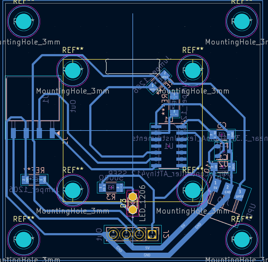
All these gadgets and connectors need boards. So those all need a design. To make programming and assembling simpler, there are some conventions:
- On the ATtiny1624
- Port A0 is UPDI (this is forced)
- Port A2 is the center LED, if the gadget has one
- Port A3 is the clock input
- Port A4 is the bottom input/output (and specifically an output except in output gadgets)
- Port A5 is the left input/output, if there is one
- Port A6 is the top input/output, if there is one
- Port A7 is the right input/output, if there is one
- Ports B0-B3 are for gadget logic as necessary (SCL/SDA for display, PWM for servo, etc.)
- UPDI pins go on the bottom right pointing down. This is very useful for orientation.
Problems that occur here are generally found during later steps, because they’re not design rule violations (according to KiCad). However, there are some here.
- In the Display gadget, the mounting holes interfere with the UPDI pins position, so they got rotated at an awkward angle to dodge both both nearby holes and the edge of the board.
- 0-delay gadgets are powered by a logic line from an ATTiny because a Falstad simulation involving using a MOSFET to control some branch of the 5V line resulted in not enough voltage for the LED. Unfortunately, this means I have to be careful about the number of 0-delay gadgets I connect in a row. 15 should be a safe maximum, giving at most (15×2+1)×0.6mA≈18.6mA of current. (The absolute maximum (§33.2) is 40mA.)
Making the Board (Scaled Up)
Lots and lots of time on the Othermill was needed to make all the gadget boards I wanted to make (to say nothing of the connectors). Each gadget board takes about 10 minutes to mill. (Gadget boards are batched in batches of 4, which take about 40 minutes.) So with 57 gadgets, that’s 9.5 hours of milling. The connectors add about 2.5 hours, for a total of about 12 hours. And this is using the Othermill, with rest machining, the reduced redundancy of the [1/64” Please Step Over], and the sheer 60in/min speed of the [1/32” Flat End Mill]. Imagine using the Roland SRM20 (with it’s maximum 7000 RPM (slower feed required)) and mods (no rest machining unless you figure it out yourself. Only the 1/64” tool gets used).
The hole sizes were changed to 3mm to account for 4-40 screws because I noticed an extreme lack of 2-56 nuts.
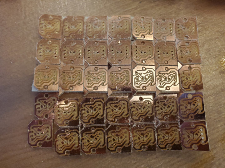
Some problems that happened:
- The boards want to be 2”×2”. But the FR1 sheets we have are 4”×5”, so I’d barely only be able to fit 2 boards on a sheet. If I chop off 0.02” from each side, I’d barely be able to fit 4 boards, even accounting for the width of the 1/32” end mill, which cuts the outlines. But then being off by 0.02” in placement is bad. So…
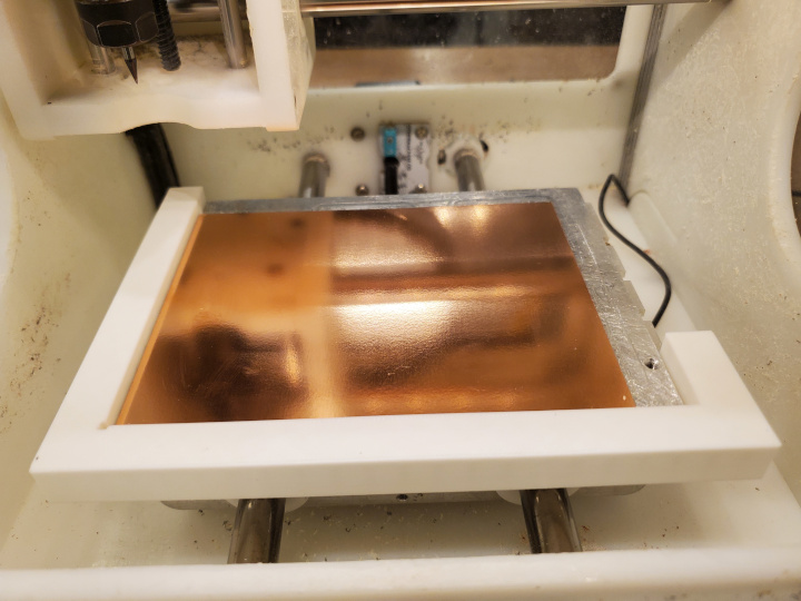
- Using an old tool will give burred traces that don’t get deburred even when attempted. And in addition it even peels off traces! Make sure the traces generated by the tool are at least deburrable and that it’s not peeling off traces before wasting 26 Othermill minutes (not my minutes, I’m busy assembling boards elsewhere).
- At one point, the y-coordinate of the mill was off, causing ground traces at the edge of two boards to be thinner than intended. Not sure what the previous person did, but the stepper motor must have skipped some steps.
- Bantam Tools has a glitch where it misinterprets the vector line primitive (page 60) and puts squares on top of the ends of the lines, even though the Gerber file spec says the line stops at the specified tip. This affects files generated from KiCad that have awkwardly-rotated through-hole footprints (where even 45° is considered awkward). The fix is to go into the affected Gerber file, find the line that looks kind of like
20,1,$1,$2,$3,$4,$5,0*, change the 20 to a 21, and hope that all the references were 0-length lines.
Assembling the Board (Scaled Up)
Little did I know the sheer hardship that would come with this step (scaled up).
The time it takes to assemble a gadget board depends on the number of IO ports it actually uses. But let’s say about 30 minutes per gadget. So for the 57 gadgets, it’s 1710 minutes, or 28.5 hours. This being a huge time sink, I tried to make sure other things were going on at the same time (milling more boards, 3D printing decorations)
And of course, there were lots of problems:
- Back to joint hell. Sometimes the IC sockets wouldn’t quite fit in the holes, even though they were supposed to be the same size as other holes that IC sockets nicely fit into. Thankfully, all these cases (except one where the traces were the aforementioned super-burred-and-even-peeled-off kind anyway) were solved with…
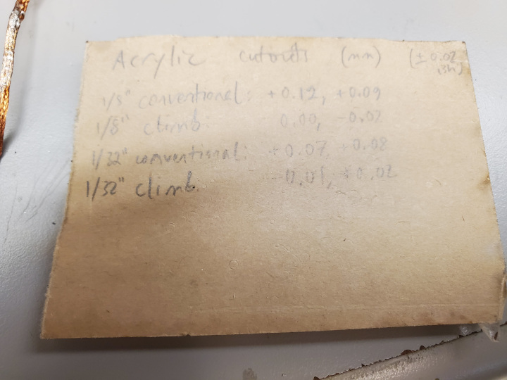
- Bridging the IC sockets to the traces is a little tricky (but once I started using lead solder since the lead-free one ran out, it became easy with short bridges and completely impossible with longer bridges (which happen when a trace gets a little peeled off when digging a hole)).
- The 4-IO-port gadgets have the microcontroller on top of some IC socket pins. Put the microcontroller on before checking that the pins are actually connected to their traces, and you’ll regret it.
- Speaking of which, sometimes traces peel off when I trim the pins so that the microcontroller isn’t elevated.
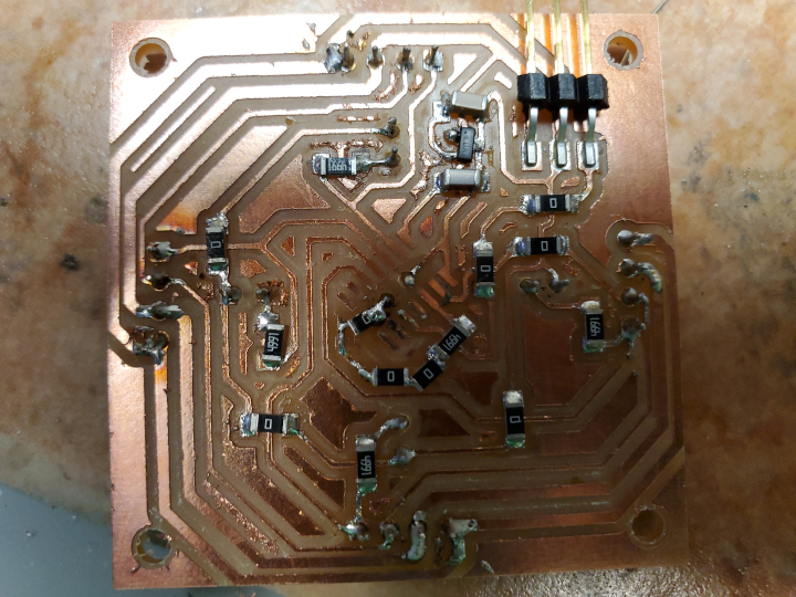
- Sometimes I would put the ATtiny1624 on the wrong way and later regret not checking the direction. If only it were more obviously not symmetric!
- Having an IC socket hole straight through a trace makes soldering more annoying because you have to solder both sides of the trace. This was avoided in future designs where possible.
- Some boards like the Main Board Connector are lopsided when put back-side up, making soldering through-hole components tricky.
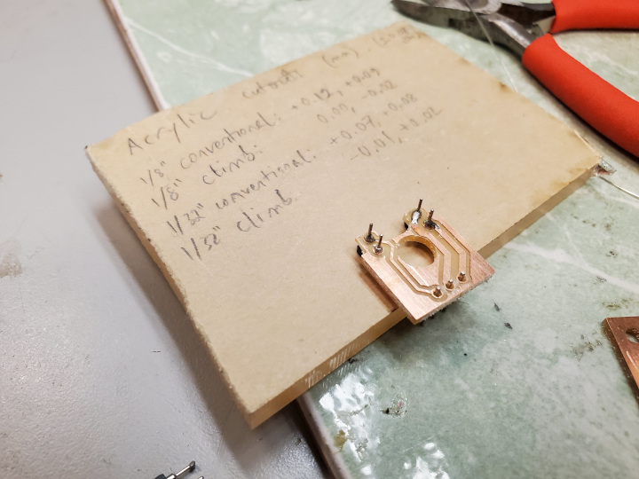
I developed a procedure that I like to call “Grand Verification” that basically checks a bunch of remotely likely shorts. This is done after assembly but before programming. The procedure is described in the replication section. But for now, I’ll just say that the last thing I want is
- a short from 5V to GND (the greatest, the worst, the most abominable short. Causes theoretically infinite current everywhere.)
- any short involving 5V, GND, or Clock (those are global and will affect every gadget)
Programming the Logic (Scaled Up)
In the OR-IIOO gadget, and all other “-IIOO” gadgets, the inputs are now A6 and A5 and the outputs are now A7 and A4 due to a goof I made involving the orientation of the center LED (it’s 90° off).
There’s lots of types of gadgets, and therefore lots of logic to program. An example looks like:
Set the program to program Delay-16-Straight gadget
#define L_DELAY 5
//...
#define LOGIC L_DELAY
Set whether A7, A6, A5, A4 are inputs or outputs
constexpr bool IO_OUTPUT[] {
#if /*...*/ LOGIC == L_DELAY /*...*/
  true, false, false, true
//...
};
//...
void setup() {
//...
    for (uint8_t i = 0; i < Pin::NUM_IO; ++i) {
        // Excuse the use of pinMode() and digitalWrite() here. Didn't get around to changing it to use registers.
        pinMode(Pin::IO[i], IO_OUTPUT[i] ? OUTPUT : INPUT);
        if (IO_OUTPUT[i])
            digitalWrite(Pin::IO[i], 0);
    }
}
Define state
#if LOGIC == L_DELAY
uint16_t delay_buffer = 0; // The delay gadget buffers its input to output it later.
Initialize other used IO pins
void setup() {
#elif LOGIC == L_DELAY
    // The 4 switches that control the delay are input pullups
    PORTB.DIRCLR = 0b1111;
    PORTB.PIN0CTRL |= 1 << 3;
    PORTB.PIN1CTRL |= 1 << 3;
    PORTB.PIN2CTRL |= 1 << 3;
    PORTB.PIN3CTRL |= 1 << 3;
Executing the logic
ISR(MSG_CLOCK_PORT_SUF(PORT_vect)) {
//...
uint8_t input = PORTA.IN & 0b11110000; // read input
asm volatile( // wait like 32 cycles so all gadgets can read their inputs
    "nop \n" "nop \n" "nop \n" "nop \n" "nop \n" "nop \n" "nop \n" "nop \n"
    "nop \n" "nop \n" "nop \n" "nop \n" "nop \n" "nop \n" "nop \n" "nop \n"
    "nop \n" "nop \n" "nop \n" "nop \n" "nop \n" "nop \n" "nop \n" "nop \n"
    "nop \n" "nop \n" "nop \n" "nop \n" "nop \n" "nop \n" "nop \n" "nop \n"
);
//...
#elif LOGIC == L_DELAY
    delay_buffer = delay_buffer << 1 | !!(input & (1 << 6)); // buffer input
    uint8_t delay = PORTB.IN; // read switches
    delay = (delay << 2 & 0b1100) | (delay >> 2 & 0b0011); // reverse bit order
    delay = (delay << 1 & 0b1010) | (delay >> 1 & 0b0101);
    bool output = delay_buffer >> delay & 1; // get appropriate buffered input
    PORTA.OUTCLR = 1 << 2 | 1 << 4; // write output straight across (and to center LED)
    PORTA.OUTSET = output << 2 | output << 4;
Some problems:
- Sometimes the test logic would reveal LEDs that aren’t working (or are brighter than they should be. This could be a 5V-3.3V short or a LED resistor short.). That means back to assembly.
- There were a few boards that couldn’t even be programmed. In two cases, UPDI wasn’t connected because the hot iron failed to properly solder some 0Ω resistors. But one case was mysterious and ended up working later.
- In one case, I plugged in GND and 5V in the wrong order and didn’t notice until there was smoke coming of the gadget board. Thankfully, only the microcontroller was damaged, so I just had to disassemble the gadget, replce it, and reassemble the gadget. That particular gadget is now nicknamed [Flamin’ Turns].
- Sometimes the test revealed that LEDs were the wrong color. Oops!
- I didn’t investigate too hard, but megaTinyCore seemed to have a bug with
pinMode(Pin::SWITCH, INPUT_PULLUP);(wherePin::SWITCHis defined asB0) where it would make an A pin have half voltage and not activate the pullup on B0. Changing the code toPORTB.DIRCLR = 1 << 0; PORTB.PIN0CTRL |= 1 << 3; // pullupfixed the half voltage problem. There may have been a short (I forgot), but after fixing the problem I moved on to other things and didn’t investigate. I’m still suspicious because
pinMode(B0, INPUT_PULLUP)andPORTB.DIRCLR = 1 << 0; PORTB.PIN0CTRL |= 1 << 3should have the same effect.
A result
Decorating the Logic (Scaled Up)
Then came decoration. Due to the amount of time left in the class, the sheer amount of milling on the Othermill that needed to be done (including by other students), the fact that I still didn’t figure out how to do different colors with the milling setup, and the fact that I encountered joint hell even with the rounding trick mentioned before, I decided to 3D print the elevated paths of the decoration and laser cut the slabs.
But before that, there were some problems to record:
- FreeCAD doesn’t import shapes with holes properly when importing SVGs. It treats the hole as a separate shape. So I had to manually do Boolean differences. Ugh
- Processing the shapes in FreeCAD takes a while
- Importing an SVG from Inkscape to Fusion requires a magic scale factor of 3.77953. Mysterious.
- Fusion even crashed, not just once, but twice, while I was doing CAM.
The elevated paths want white markings on top to show what the gadget does, but the rest should still be black.
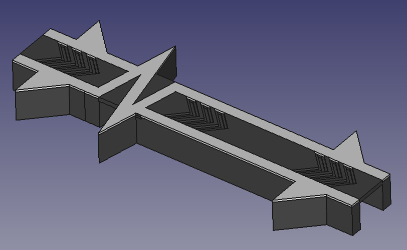
This means multi-color 3D printing. Unfortunately, I haven’t used the Bambu yet and besides, there’s only one of them, while there’s 2 Prusa MK4s. Thankfully, there’s a way to simulate multiple extruders in PrusaSlicer.
- Under Printer Settings > General, set the number of extruders to 2 and check Single Extruder Multi Material.
- Under Printer Settings > Custom G-code > Tool Change G-code, type
M600. This triggers the manual filament change process. - Set the correct extruders for your parts.
I tried printing this. Unfortunately, when it came time for the filament change to the second color, the filament didn’t release properly and I had to open up this thing the machine calls the “idler” and manually cut out the bulby end. However, this works unless the filament is not just unable to move up, but also unable to move down (so you can reach the end and cut it off). Which has happened like 3 times. Each time I needed to call in Anthony to fix the machine.
At one point, I remembered doing this without a wipe tower, and the filament unloaded perfectly. So I finally decided to try without the wipe tower again. And it worked. I suspect that there’s a problem with the wipe tower because the printer starts unloading the filament before finishing printing the wipe tower. There’s more evidence: one time I forgot the M600 and it started unloading the filament and continued to print. When I stopped the print and tried to unload the filament, the glitch happened.
So…
- Under Print Settings > Multiple Extruders, uncheck the wipe tower.
You may notice that in the picture above of the elevated path for the delay gadget, the chevrons are funky. This is because the elephant foot compensation in PrusaSlicer doesn’t make the gaps between chevrons narrower on the first layer (it keeps it as 2 nozzle widths, which doesn’t compensate at all). That caused the chevron holes to collapse. So I had to compensate manually. Hence the funky chevrons.
Then I laser cut the slabs on black 3mm thick acrylic with a Universal laser cutter. I engraved the grooves that the elevated paths go on (100% power, 100% speed, 1000 dpi) and vector cut the outlines (100% power, 4% speed, 1000 dpi). I also laser cut bottom slabs to protect the back side of the board.
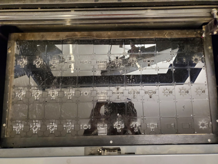
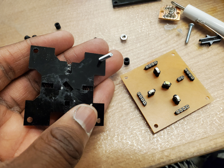
In the slabs, there are little indents for the nuts of the connectors to go through. I didn’t account for the nuts earlier and found out that I needed them the kind of hard way (only 1 slab was cut.) However, disassembly proved harder than expected.
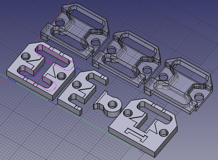
Speaking of slabs and bottoms, I 3D printed the ones for the connectors because I thought the top slabs needed to be thinner than 3mm (they didn’t) and the bottom slabs were a more complex shape with vaults and angles.
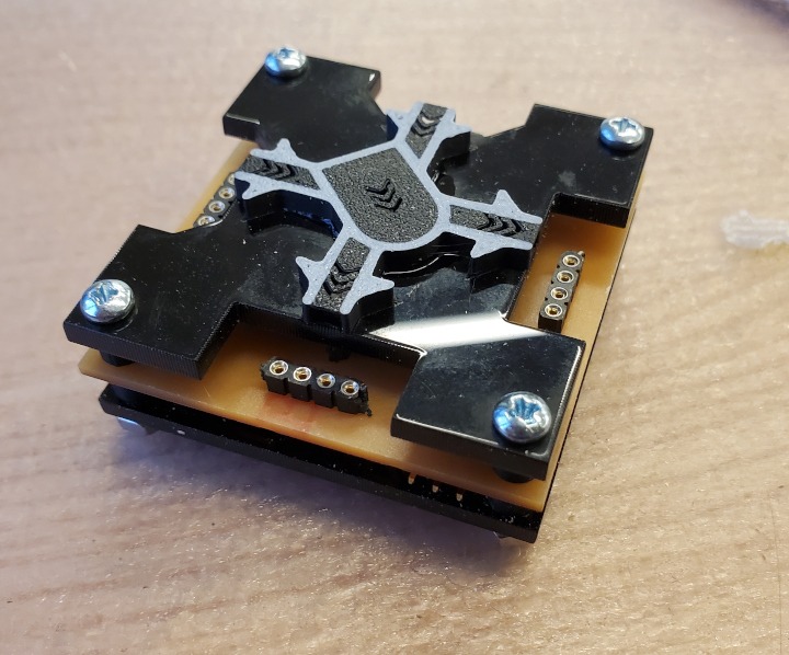
I did some measurements and 3D printed spacers to go between the slab and the board, and between the board and the bottom slab. They came out to 4mm on top and 4.84mm on the bottom. But then I noticed that when I tried to put a connector on, I messed up and the connector was elevated too high. So I just swapped the spacers and put the tall ones on top. I used 4-40 3/4” screws to hold everything in place. And behold!
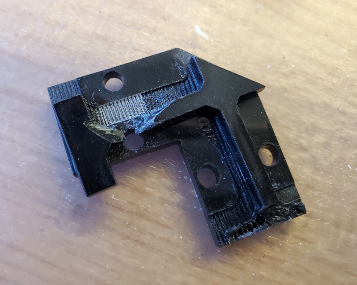
The 0-delay gadgets are narrower than other gadgets. The screws can’t go in their usual place. If I must move them inward, they block the connectors. If I move them further away from the connector positions, then you have torque problems when trying to attach a connector. So I moved them further away, but also added a piece that goes on the bottom to level it out and dodge torque. Except that in one case, for some reason the piece shifted before the glue settled, and then the glue settled, and then I just had to deal with it with some pliers.
Intermediate Gallery
And now for an intermediate gallery.
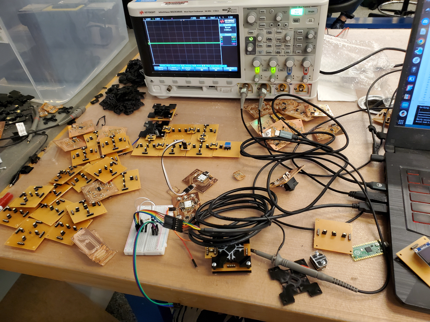

That was a lot of information. So I will say how to replicate the fabrication, and then how to improve it.
Replicating the Logic
This assumes you make the exact quantities of gadgets listed under Types of Gadgets (and Counts). You may want to make more 0-delay gadgets, inverters, crossovers, splits, and true connectors, however.
You will need:
Machines
- Bantam Tools Othermill V2
- 3/32” carbide flat end mill
- some 1/32” carbide flat end mills
- some 1/64” carbide flat end mills
- Universal Laser Systems C02 laser cutter (don’t remember the wattage)
- Prusa MK4 3D printer
For the electronics:
- 16 4”×5” FR-1 single-sided boards
- 49 ATtiny1624s
- 1 XIAO RP2040
- 229 0Ω resistors
- 5 499Ω resistors
- 235 4990Ω resistors
- 57 0.1μF capacitors
- 49 1μF capacitors
- 53 5V-3.3V 100mA regulators
- 52 rows of 3 horizontal pin headers each
- 3 Cherry RS power switches (the black one in the link)
- 3 Omron B3F-40xx buttons (12mm×12mm, the blue ones typically used in electronics kits.)
- 2 micro servos
- 49 white LEDs
- 62 blue LEDs
- 71 red LEDs
- 61 orange LEDs
- 5 green LEDs
- 16 slide switches
- 259 rows of 4 and 443 rows of 2 single-row IC sockets (XR2C, DIP terminals)
- 3 rows of 3 vertical through-hole pin headers
- 2 rows of 3 socket-socket jumper wires
- 1 2×2 surface mount vertical pin header
- Solder. Lots of it.
- A metal file (sorry).
- A way to program the ATtiny1624s using UPDI (tricky) and XIAO RP2040 (just use a USB cord)
For the decoration:
- 2 sheets of 12”×24” 3mm-thick black cast acrylic (not extruded)
- 1 sheet of 12”×24” 1.5mm-thick clear acrylic
- Some black, white, and yellow PLA filament
- 228 4-40 3/4” screws
- 114 4-40 1/2” screws
- 342 4-40 nuts
- 2 2-56 1/2” screws
- 2 2-56 nuts
- Instant adhesive (what some people called “superglue”. I used cyanoacrylate)
And of course, this zip file, which contains a lot of important files.
Replicating the Electronics
Replicating the Milling
In the zip file, in the Boards folder, there’s a bunch of kicad_pcb files. Those correspond to gadgets in the following way:
| Gadget | File |
|---|---|
| OR-IIOO | Diagonal General |
| AND-IIOO | Diagonal General |
| XOR-IIOO | Diagonal General |
| Crossover | Vertical General |
| Mux-LHSO | Vertical General |
| Split-OIO | 3-Way Split |
| Memory-IWO | 3-Way General |
| NOT-Straight | Straight General |
| Delay-16-Straight | Straight Delay |
| 0-Delay-Straight | 0-Delay Straight |
| 0-Delay-Turn | 0-Delay Turn |
| Button | In Button |
| Switch | In Switch |
| Light | Out Light |
| Servo | Out Servo |
| Connector | Connector |
| Powerable Connector | Connector |
| True Connector | True Connector |
There’s also Main Board Connector (3 required) and Main Board (1 required) for the non-gadget stuff that’s still needed for power.
They should be imported into KiCad, duplicated to the appropriate quantities, and arranged to fit 4”×5” boards (while leaving 0.04” space between boards). Plot front, back, edge cuts, and holes, making sure to combine PTH and NPTH holes.
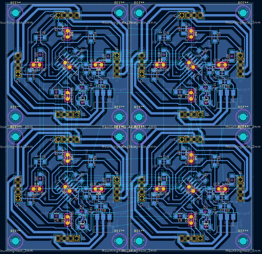
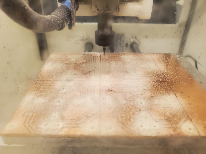
For the non-connectors, just import the plotted files into Bantam Tools for the Othermill. Unless it’s the main board, flip the board in the software, since the traces are on the back. Position it appropriately in software, making sure the material thickness is 1.64mm and the Z placement is 0.14mm. Use 3M double-sided carpet tape to attach the FR-1 board to the mill’s spoilboard, copper side up. Add the 1/64” end mill if necessary (You can use the [1/64” Please Step Over] settings (1/64” end mill, 24 in/min, 0.15mm stepdown, 45% stepover) to speed things up). And mill!
The connectors are more complicated. You also need to plot the [Edge Cuts] and [User 3] layers as edge cuts. Let’s call this the indent job. And it’s a double sided milling job, but still with single-sided FR-1. Therefore, attach and locate the alignment bracket (that should come with the machine). Set up front-side milling in the software. Set the material thickness to 0.9mm and the material placement Z to 0.88mm. Select the edge cuts file from the indent job (which will mark it as the top side), and select it again for the profile (which is just for alignment). Make sure there’s a file selected for the holes. Replace the 1/32” flat end mill with a 3/32” flat end mill. Then attach the FR-1 board copper-side down and mill only the holes.
After that, flip the board, set up back-side milling, set the material thickness and material placement Z back to their usual values of 1.64mm and 0.14mm, respectively, upload the regular job, make sure its placement matches the placement of the indent job, and mill.

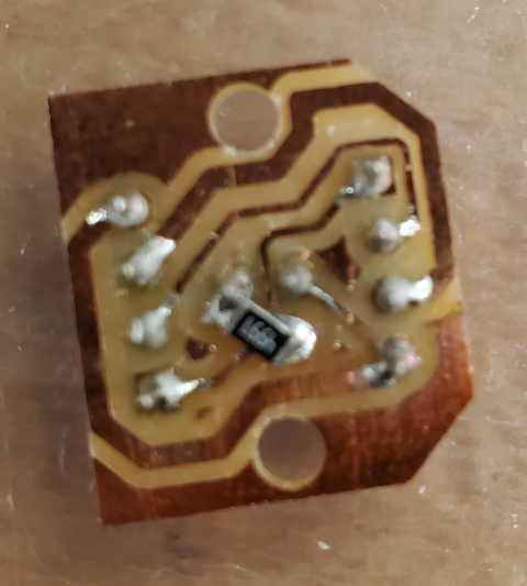
Replicating the Soldering
Now it’s time to solder the board. Unfortunately, I have to recommend leaded solder over lead-free solder, both for traditional soldering (more stable bridges1) and reflow soldering with hot air (less suspicious blobs2).
- Solder the IC sockets. Every single hole that isn’t a button hole, a switch hole, a servo hole, a hole in the Main Board, or the row of 3 holes in the Main Board Connector gets an IC socket. This can be tricky. If a trace burns and becomes impossible to bridge, you may have to use copper tape or a 0Ω resistor.
- Solder the resistors, capacitors, regulators, and surface-mount pin headers. Also include the microcontrollers, except in the case of 4-port gadgets. I recommend using paste and hot air. Pay attention to direction for the microcontrollers!
- In the 4-port gadgets, check with a multimeter that the row of 2 IC sockets in the center is actually connected to the traces. You don’t want to find out they’re not connected after hiding the connection point with the microcontroller. Then solder the microcontroller (mind the direction!). You may need to bridge some connections. Vertical bridges are good. Horizontal bridges are bad.
- Solder the vertical through-hole pin headers onto the Main Board Connectors.
- LED time. In all the gadgets, but not the connectors, plug in another row of 2 IC sockets on top of each existing row of 2 IC sockets on the front side (not the copper side, which is the back). The connectors will already be elevated, so they don’t get another row. In the Delay-16-Straight gadget, skip the IC sockets that are angled awkwardly.
- In True Connectors, solder a green LED to the row of 2 IC sockets, on the front side of the board. Direction!
- In all other connectors, and 0-delay gadgets, make that an orange LED.
- In all gadgets that are not connectors or 0-delay gadgets, use the diagram below to figure out which LEDs to solder onto which rows of 2 IC sockets.
- In the Delay-16-Straight gadget, solder slide switches onto the remaining rows of 2 IC sockets. Go from right to left (bottom left to top left, if you’re using the diagram’s orientation) to make things easier.
- In the Button and Switch gadgets, plug in and solder a button and power switch, respectively.
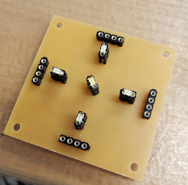
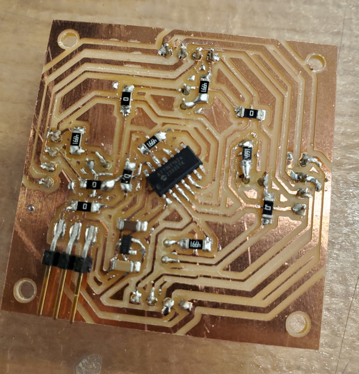
Whew, that was a lot of soldering. And there’s no way you (or the hot air reflow, for that matter) did it perfectly every time. So now for what I like to call Grand Verification.
- Check for shorts between GND, 5V, Clock, and IO. (Should be done on the front side. The IC socket holes are convenient for this)
- Check that GND is connected to the cathodes of the LEDs.
- Check that GND is connected, that 5V is connected, and that Clock is connected (front side, except for the 1-port gadgets)
- Check that IO IC socket pins are connected to their traces. Also do this for LED anodes.
- Check for shorts between resistors and any traces crossing under them (both 0Ω and resistors with resistance. For resistors with resistance, check both sides of the resistor)
- Check for shorts across resistors that have resistance
- Check that 0Ω resistors actually connect their sides
- Check for shorts across microcontroller pins (including 3.3V to GND)
- Check that the microcontroller pins are actually connected to their traces
- Check for 5V to 3.3V short
- Look at capactitors and resistors and make sure they look like they’re soldered properly
And now to test the boards (well, the ones with ATtiny1624s on them).
You’ll need Arduino and megaTinyCore.
Plug in your ATtiny1624 programming method into the UPDI pin header and your computer. In the zip file, there’s an Arduino project called logic-gadget-code. In that file, comment out the #define LOGIC ... line. Set the board and port appropriately, and set the chip to ATtiny1624. Then program the microcontroller. If everything was done right, the LEDs on the front side should light up.
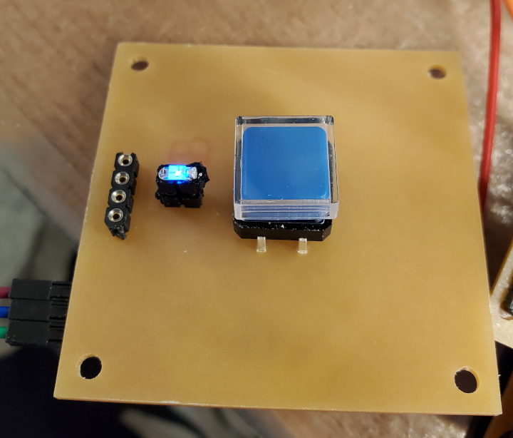
Eventually the boards will be programmed with their proper logic, but first…
Replicating the Decorating
Replicating the 3D Printing
First of all, we need a lot of tube shaped spacers. That’s:
- 228 tall spacers (height 4.8mm, outer diameter 5mm, inner diameter 3mm)
- 228 short spacers (height 4mm, outer diameter 5mm, inner diameter 3mm)
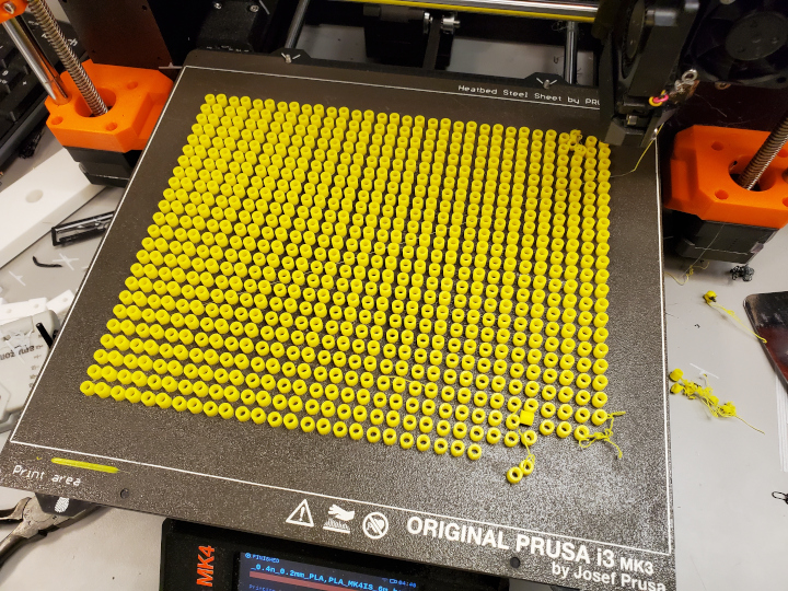
There’s one of each in Decoration/Spacers.step. This should be imported into PrusaSlicer and duplicated a bajillion times (more than 227. You want backups in case a few of them fail to print or roll away. I had 384 copies of each and like 20 total spacers were lost.). Slice and print with your favorite color.
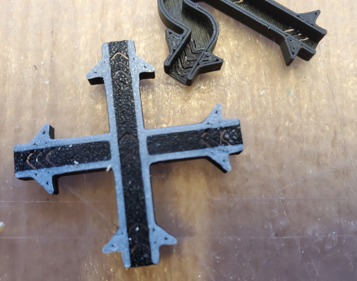
Next, there’s a file called Decoration/Gadgets Top.3mf that has a copy of the elevated path of each gadget. This should be duplicated appropriately and printed. Of note:
- This is a 3-extruder job being simulated with 1 extruder.
- Under Printer Settings > Custom G-code > Tool Change G-code, there should be a
M600. Make sure it’s there. It triggers the filament change sequence. - Under Print Settings > Multiple Extruders, the wipe tower should be disabled. Enabling it causes problems with filament changing.
Split and print. The filament changes are to white, yellow, and black, in order.
Finally, there’s the slabs for the connectors, which are in Decoration/Connector Slabs.step and should be duplicated appropriately and 3D printed with black filament.
Replicating the Laser Cutting
There’s a file called Decoration/Black Laser.svg. It contains the slabs of all the gadgets (that aren’t connectors), and also the bottom parts. Remove the labels (all the pink-fill stuff. In Inkscape there’s a way to select all objects with the same fill color.) Duplicate and laser cut on black 3mm thick cast acrylic (not extruded) with
- 100% power, 100% speed, 1000 dpi for black raster
- 100% power, 4% speed, 1000 dpi for red vector
(settings may vary; I forgot the wattage of the laser that I used)
Decoration/Clear Laser.svg contains the “shield”s for the connectors. Remove the labels. These should be duplicated and laser cut on 1.5mm thick extruded acrylic (or cast if you can find it. Doesn’t matter) with 100% power, 10% speed, and 1000 dpi.
Replicating the Assembly
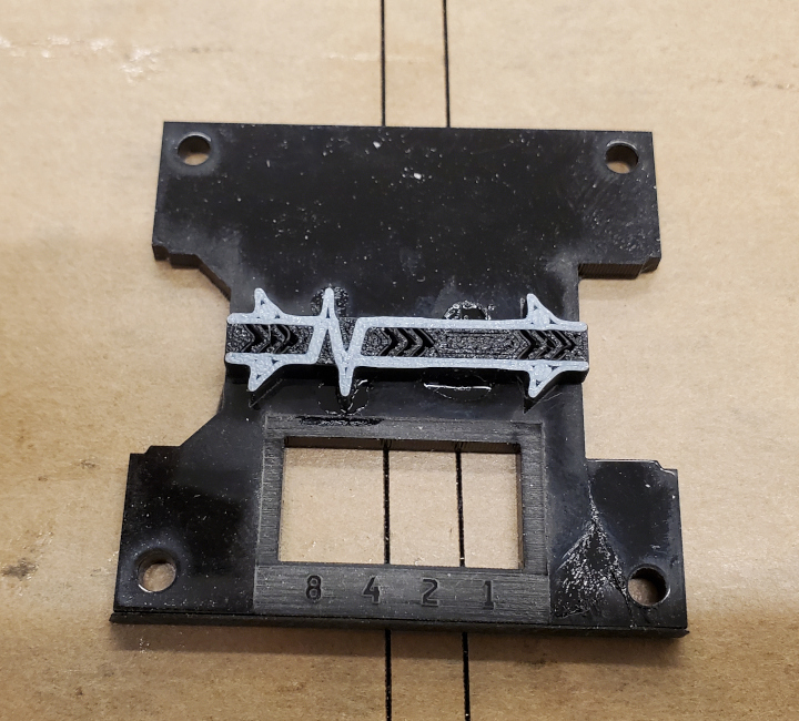
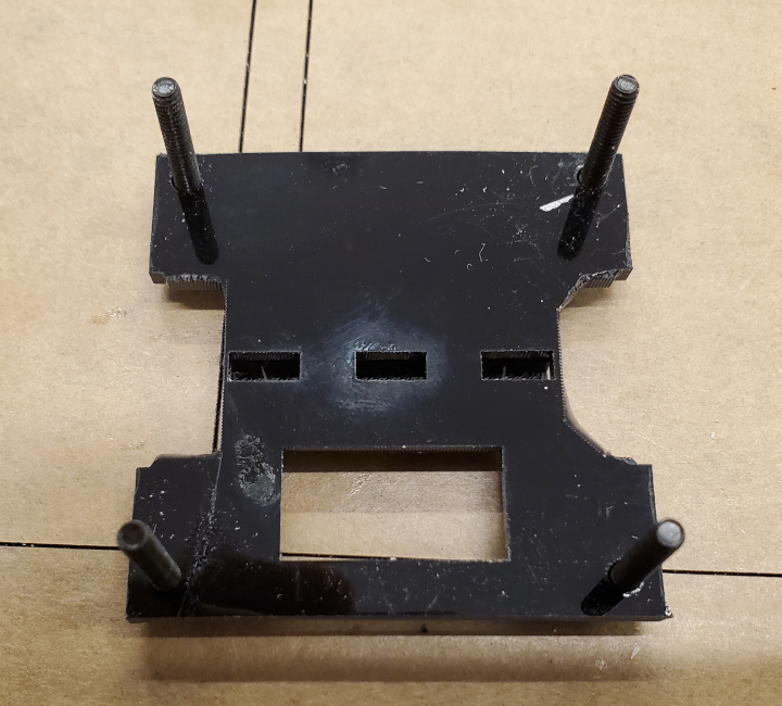
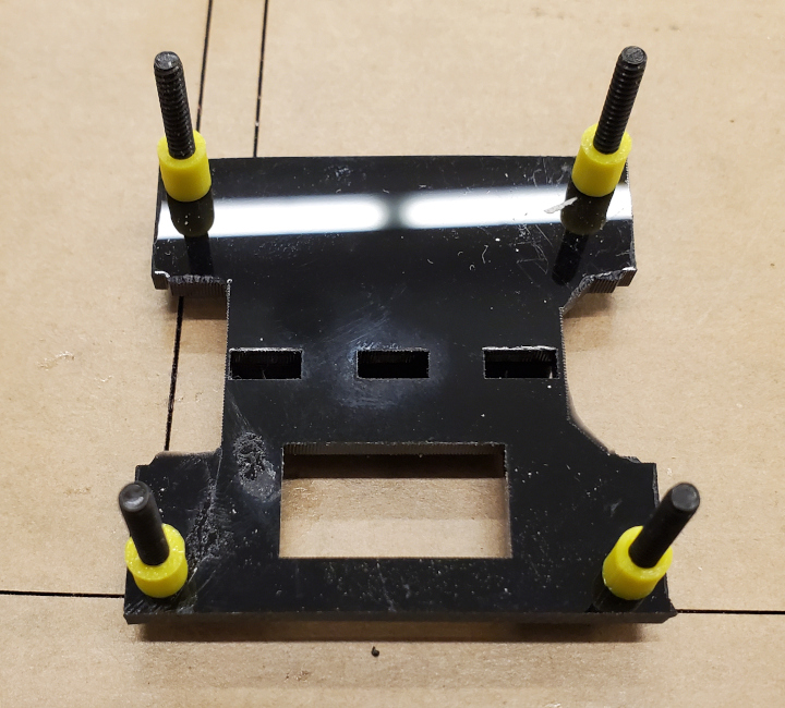
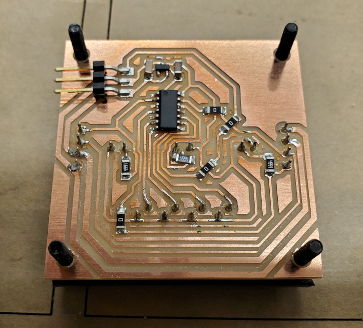
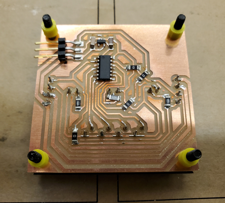
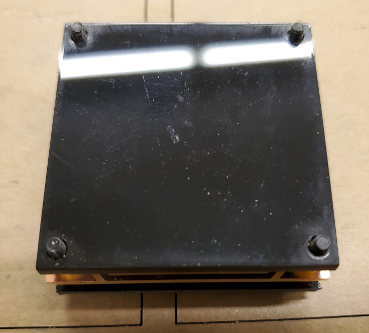
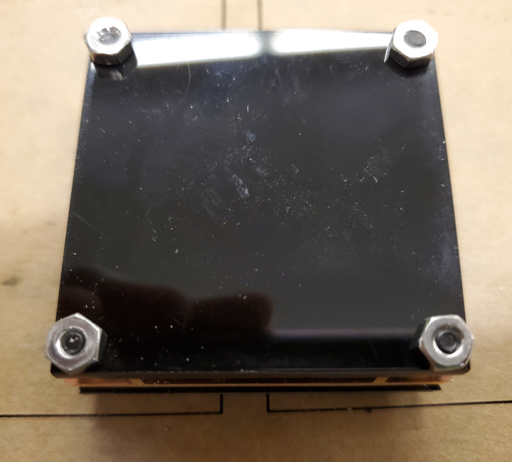
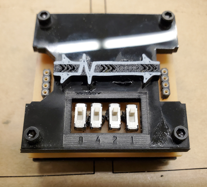
Servo gadget assembly is a little more complicated. You want to thread the servo through the top slab and the board, wrap around its wires, and plug its wires into the servo pin header. You may need to do some filing on the board to get the servo wires to go through. Afterwards, use a 2-56 1/2” screw on the non-wire side of the servo to mount it (nut goes on the board), and use tape because you can’t fit a screw on the wire side.
You use socket-socket jumper wires to connect the Main Board to a Main Board Connector, and to connect two Main Board Connectors together (for power transfer).
Improving the Logic
There’s a lot of room for improvement.
Improving the Board
- I think I’ve had a 2-digit number of solder joints (specifically through-hole joints) break on me. Figuring out strain relief would be a good idea.
- Be less afraid of using the 1/64” tool when it comes to copper rings around holes. Having a ring there makes soldering easier, and makes the joint more sturdy.
- IC sockets might not be the best interfacing option.
- The pins are thin and easily bend (though thanks to the connector bottom slabs, the important ones haven’t bent on me)
- Soldering the rows of 4 IC sockets on the connectors makes it easy to get solder on the pins themselves, which is bad for fitting them into the IC sockets on the boards.
Perhaps it’s a good idea to explore pogo pins, which someone else used for their modular project.
- Using through-hole switches instead of attaching switches to IC sockets may be a good idea
- In general, finding methods to speed up board soldering.
- The True Connector doesn’t fit in areas were the other side expects an input. The design should be changed so it doesn’t care about the other side.
Improving the Decoration
- First and foremost, find a good way to mill acrylic without getting the chips stuck, and solve joint hell. I’d like those thin acrylic chevrons back. They were so beautiful.
- Perhaps use the levellers on the 0-delay gadgets everywhere to get an even height across all gadgets.
Improving the Number
- Add more gadget types! A Display gadget and a Speaker gadget would be nice output gadgets. In addition, I wanted to add some permutation of Full-Adder gadget, but didn’t get around to it. The Full-Adder gadget would be a nice way to explore fat gadgets (which take up more than 1 space).
- The working paths file is here.